Camera driving box with automatic adjusting mechanism
Technical Field
The utility model relates to the technical field of camera driving boxes, in particular to a camera driving box with an automatic adjusting mechanism.
Background
The main body of the shooting action is a photographer, a shot object and a shooting device, the shot object is used as a reference for focusing, and a picture is recorded in the shooting device. The operation process of picture taking comprises the following steps: long shot, panoramic, medium shot, close-up, microscopic, etc.
Most of the existing camera driving boxes are inconvenient to adjust the height in the using process; in addition, the camera driving box is not provided with a standby power supply, cannot work under the condition of power failure and is not beneficial to use, so that the camera driving box with the automatic adjusting mechanism is provided.
SUMMERY OF THE UTILITY MODEL
The utility model aims to provide a camera driving box with an automatic adjusting mechanism, which is convenient to adjust the height of the camera driving box by adding a height adjusting mechanism and a battery box on the structure of the camera driving box, can still continuously work under the condition of power failure, is more beneficial to use and solves the problems in the background technology.
In order to achieve the purpose, the utility model provides the following technical scheme:
the utility model provides a drive box of making a video recording with automatic regulating mechanism, includes drive box body and bottom plate of making a video recording, bottom plate top one side fixed mounting has the set casing, inboard bottom one side fixed mounting of set casing has electric motor, electric motor one side and drive box body one side electric connection of making a video recording, electric motor output shaft fixed mounting has adjusting screw, the inside slidable mounting of set casing has the lifter, first screw hole has been seted up to the lower extreme of lifter, first screw hole one end runs through the lifter, adjusting screw thread installs inside first screw hole, the drive box body of making a video recording includes the casing, casing one side fixed mounting has the fixed block, the inside battery case that has pegged graft of fixed block, battery case one side and drive box body one side electric connection of making a video recording.
Preferably, two sets of chutes are formed in the inner wall of the fixing shell, the chutes are symmetrically arranged relative to the fixing shell, two sets of sliders are fixedly mounted at the lower end of the outer wall of the lifting rod and symmetrically arranged relative to the lifting rod, and the sliders are respectively slidably mounted inside the chutes.
Preferably, a through hole is formed in one side of the top of the fixing shell, the cross section of the through hole is of a circular structure, and the lifting rod is arranged on the inner side of the through hole.
Preferably, a fixing groove is formed in one side of the top of the fixing block, the cross section of the fixing groove is of a rectangular structure, and the battery box is fixedly inserted into the fixing groove through a handle bolt.
Preferably, a second threaded hole is formed in one side of the fixing block, one end of the second threaded hole is communicated with the inside of the fixing groove, the handle bolt is installed in the second threaded hole in a threaded mode, and one end of the handle bolt penetrates through the second threaded hole to be tightly pressed and attached to one side of the battery box.
Preferably, the top of the bottom plate is provided with four groups of fixing holes, and the four groups of fixing holes are respectively arranged at four corners of the bottom plate.
Preferably, a coupler is fixedly mounted at an output shaft end of the electric motor, one end of the coupler is fixedly connected with the lower end of the adjusting screw, and the electric motor is provided with a forward and reverse rotation speed reducing motor.
Compared with the prior art, the utility model has the beneficial effects that:
1. according to the utility model, the fixed shell, the electric motor, the adjusting screw and the lifting rod are matched for use, so that the height of the camera shooting driving box body can be adjusted, and the camera shooting driving box is more convenient to use.
2. Through the setting of battery case, under the condition that has a power failure, the battery case can provide the electric energy for making a video recording drive box, makes the drive box that makes a video recording continue work, more does benefit to the use.
Drawings
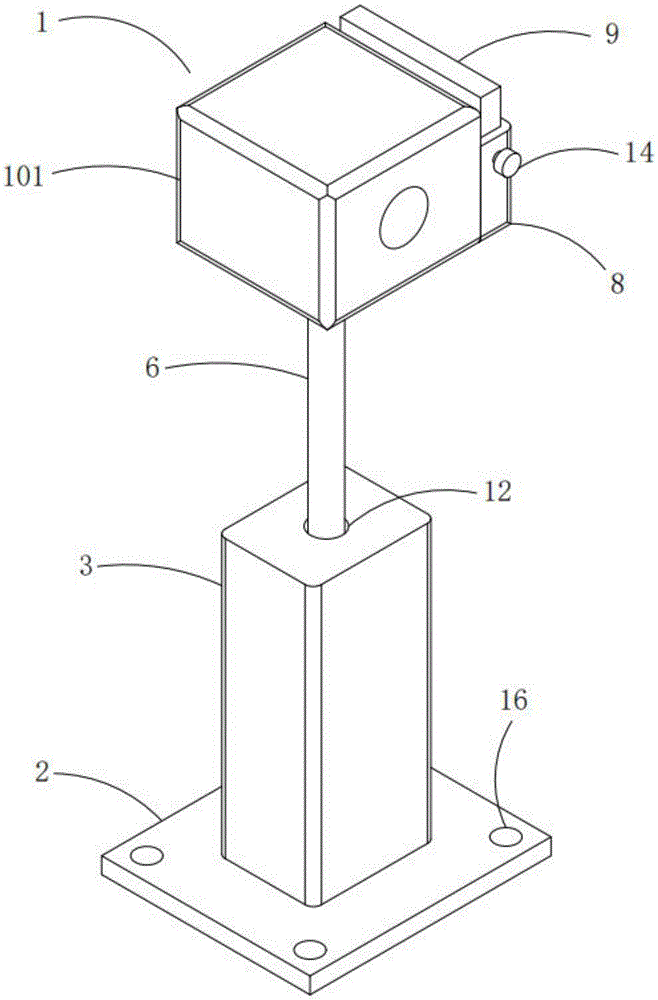
FIG. 1 is a schematic structural view of the present invention;
FIG. 2 is a schematic cross-sectional view of the stationary housing of the present invention;
FIG. 3 is a schematic view of the fixing block and the battery case according to the present invention;
fig. 4 is an exploded view of the fixing block and the battery case according to the present invention.
In the figure: 1. a camera driving box body; 101. a housing; 2. a base plate; 3. a stationary case; 4. an electric motor; 5. adjusting the screw rod; 6. a lifting rod; 7. a first threaded hole; 8. a fixed block; 9. a battery case; 10. a chute; 11. a slider; 12. a through hole; 13. fixing grooves; 14. a handle bolt; 15. a second threaded hole; 16. a fixing hole; 17. a coupling is provided.
Detailed Description
The technical solutions in the embodiments of the present invention will be clearly and completely described below with reference to the drawings in the embodiments of the present invention, and it is obvious that the described embodiments are only a part of the embodiments of the present invention, and not all of the embodiments. All other embodiments, which can be derived by a person skilled in the art from the embodiments given herein without making any creative effort, shall fall within the protection scope of the present invention.
Referring to fig. 1-4, the present invention provides a technical solution:
the camera driving box with the automatic adjusting mechanism comprises a camera driving box body 1 and a bottom plate 2, a fixed shell 3 is fixedly installed on one side of the top of the bottom plate 2, the fixed shell 3 is used for installing an electric motor 4 and a lifting rod 6, the electric motor 4 is fixedly installed on one side of the bottom of the inner side of the fixed shell 3, the height of the lifting rod 6 can be changed by matching the electric motor 4, an adjusting screw 5 and a first threaded hole 7, one side of the electric motor 4 is electrically connected with one side of the camera driving box body 1, the adjusting screw 5 is fixedly installed on an output shaft end of the electric motor 4, the lifting rod 6 is slidably installed in the fixed shell 3, the lifting rod 6 is used for installing the camera driving box body 1 and driving the camera driving box body 1 to move, the first threaded hole 7 is formed in the lower end of the lifting rod 6, one end of the first threaded hole 7 penetrates through the lifting rod 6, and the adjusting screw 5 is installed in the first threaded hole 7, drive box body 1 makes a video recording includes casing 101, and casing 101 one side fixed mounting has fixed block 8, and fixed block 8 is used for installing battery case 9, and 8 inside pegs graft of fixed block have battery case 9, and battery case 9 is used for the drive box body 1 power supplies for making a video recording under the condition that has a power failure, battery case 9 one side and drive box body 1 one side electric connection that makes a video recording.
Two sets of spouts 10 have been seted up on the inner wall of set casing 3, and two sets of spouts 10 are relative to the 3 symmetry settings of set casing, and the lower extreme fixed mounting of 6 outer walls of lifter has two sets of sliders 11, and two sets of sliders 11 are relative to the 6 symmetry settings of lifter, and two sets of sliders 11 are respectively slidable mounting inside two sets of spouts 10, and spout 10 and 11 cooperation use are used for slidable mounting lifter 6, can increase the stability that lifter 6 removed simultaneously.
Through-hole 12 has been seted up to set 3 top one side of set casing, and the cross-section of through-hole 12 sets up to circular structure, and lifter 6 sets up in through-hole 12 inboardly, and the setting of through-hole 12 is convenient for lifter 6 to remove.
Fixing groove 13 has been seted up to 8 top one sides of fixed block, and fixing groove 13 is used for installing battery case 9, and the cross-section of fixing groove 13 sets up to the rectangle structure, and battery case 9 passes through handle bolt 14 to be fixed pegging graft inside fixing groove 13, utilizes handle bolt 14 to fix the position of battery case 9, makes the dismouting of being convenient for of battery case 9.
Second screw hole 15 has been seted up to fixed block 8 one side, and the one end and the fixed slot 13 inside intercommunication of second screw hole 15, handle bolt 14 screw thread are installed inside second screw hole 15, and second screw hole 15 is passed to handle bolt 14 one side compresses tightly the laminating with battery case 9 in one end, and second screw hole 15 is used for installing handle bolt 14.
Fixing holes 16 are formed in the top of the bottom plate 2, four groups of fixing holes 16 are formed in the bottom plate 2, the four groups of fixing holes 16 are respectively formed in four corners of the bottom plate 2, and the fixing holes 16 are used for being matched with bolts to install the bottom plate 2.
The output shaft end of the electric motor 4 is fixedly provided with a coupler 17, the coupler 17 is used for fixedly connecting the output shaft end of the electric motor 4 with the lower end of the adjusting screw 5, one end of the coupler 17 is fixedly connected with the lower end of the adjusting screw 5, and the electric motor 4 is provided with a forward and reverse rotation speed reducing motor.
The main innovation point of the present invention is that a height adjusting mechanism and a battery box 9 are added to the structure of the camera driving box, and the specific structure of the camera driving box body 1 will not be described in detail herein.
When the camera shooting driving box is used specifically, when the height of the camera shooting driving box body 1 needs to be adjusted, the electric motor 4 is started through remote control equipment configured on the camera shooting driving box body 1, the electric motor 4 rotates to drive the adjusting screw 5 to rotate, and the adjusting screw 5 rotates to change the height of the lifting rod 6, so that the height of the camera shooting driving box body 1 is changed; when having a power failure, battery case 9 provides the electric energy for drive box body 1 makes a video recording, makes drive box body 1 can continue work, and drive box body 1 when normally working makes a video recording simultaneously can charge for battery case 9.
Although embodiments of the present invention have been shown and described, it will be appreciated by those skilled in the art that changes, modifications, substitutions and alterations can be made in these embodiments without departing from the principles and spirit of the utility model, the scope of which is defined in the appended claims and their equivalents.