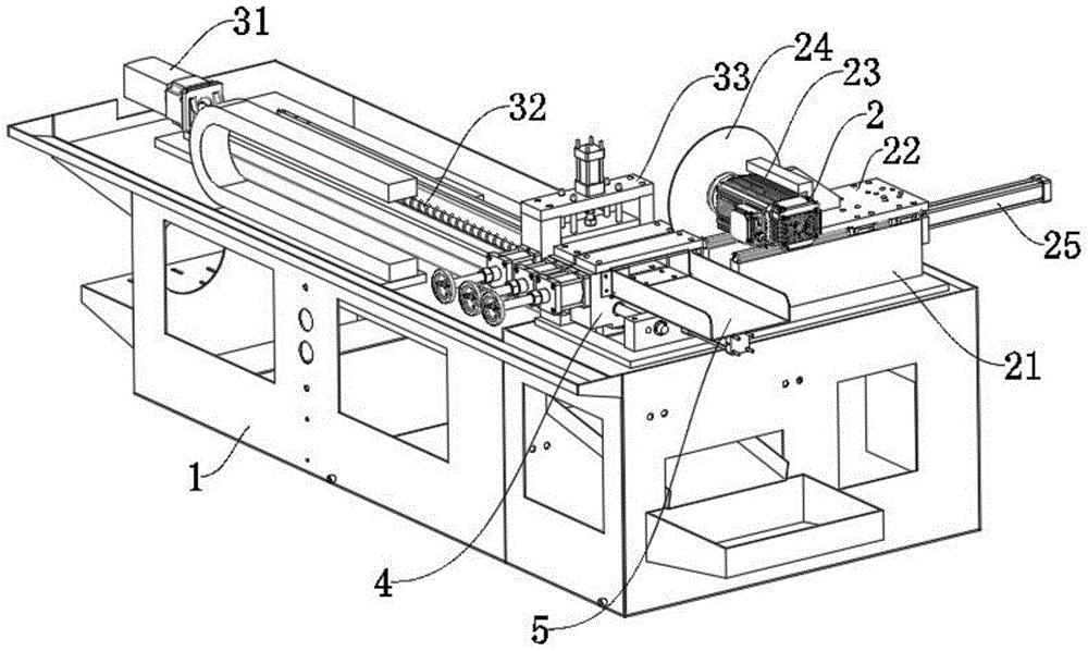
Transverse cutting machine for aluminum pipe processing
Technical Field
The utility model relates to the technical field of aluminum pipe processing, in particular to a transverse cutting machine for aluminum pipe processing.
Background
The aluminum alloy has high strength and light weight, is widely used for processing some metal products at present, and needs to be cut, punched and other series of processing according to the actual conditions of the metal products during processing.
The transverse cutting machine is a device for transversely cutting and processing an aluminum pipe, and the traditional transverse cutting machine needs manual feeding and material returning and affects cutting efficiency and cutting precision.
Therefore, it is necessary to design a transverse cutting machine for aluminum pipe processing to solve the above problems.
SUMMERY OF THE UTILITY MODEL
The utility model aims to provide a transverse cutting machine for processing an aluminum pipe, which aims to solve the problem that the cutting efficiency and the cutting precision are influenced by manual feeding and material returning in the background technology.
In order to achieve the purpose, the utility model provides the following technical scheme: a transverse cutting machine for processing aluminum pipes comprises a processing table and a cutting assembly, wherein the cutting assembly is arranged on the upper surface of the processing table and comprises a supporting seat, the supporting seat is fixed on the processing table, a first supporting plate is connected to the upper surface of the supporting seat in a sliding manner, a first motor is fixed to the outer surface of the first supporting plate, a cutting blade is fixed to the output end of the first motor, an automatic feeding assembly and a pulling mechanism are arranged on the upper surface of the processing table, the automatic feeding assembly comprises a second motor and a fixing mechanism, a screw rod is fixed to the output end of the second motor, first linear slide rails are arranged on two sides of the screw rod, a first sliding block is connected to the outer surface of each first linear slide rail in a sliding manner, the fixing mechanism comprises a second supporting plate, the first sliding block is fixed to the bottom of the second supporting plate, and a threaded sleeve is fixed to the bottom of the second supporting plate, the screw rod runs through the threaded sleeve and is in threaded connection with the threaded sleeve, a support frame is fixed to the upper surface of the second support plate, a second cylinder is fixed to the top end of the support frame, and a first clamping plate is fixed to the output end of the second cylinder.
Preferably, draw material mechanism to include that first draws material subassembly, second to draw material subassembly and fixing base, the fixing base is fixed on the processing platform, the external fixed surface of fixing base has the fifth cylinder, first draws material subassembly includes the first material seat that draws, the output and the first material seat that draws of fifth cylinder are connected fixedly, the external fixed surface of fixing base has the third guide arm.
Preferably, a third cylinder is arranged below the first material pulling seat, a first supporting plate is fixed at the top end of the third cylinder, the output end of the third cylinder penetrates through the first supporting plate and is fixedly connected with the lower surface of the first material pulling seat, a first guide rod is fixed on the outer surface of the first supporting plate, the top end of the first guide rod penetrates through the first material pulling seat and is fixed with a second clamping plate, and a distance-adjustable clamping mechanism is arranged on the side surface of the first material pulling seat.
Preferably, the distance-adjustable clamping mechanism comprises a cylinder barrel, the cylinder barrel is fixedly connected with the first material pulling seat, a piston is telescopically connected inside the cylinder barrel, a lead screw penetrates through the piston and is connected with the piston through threads, a clamping block is movably connected to one end of the lead screw and is arranged in the first material pulling seat, and a hand wheel is fixed to the other end of the lead screw.
Preferably, a collecting hopper is fixed on the outer surface of the processing table, a waste material groove is arranged below the collecting hopper, and the waste material groove is fixed on the processing table.
Preferably, one side of the supporting seat, which is far away from the material pulling mechanism, is provided with a first air cylinder, the first air cylinder is fixed on the processing table, and the output end of the first air cylinder is fixedly connected with the first supporting plate.
Preferably, the second draws the material subassembly to constitute by the second and draws material seat, fourth cylinder, second layer board, second guide arm and third splint, and the second draws the material seat to set up and draws the material seat side and fix on the processing platform at first, the third guide arm deviates from the one end of fixing base and runs through first drawing the material seat and draw material seat fixed connection with the second, first drawing the material seat and third guide arm sliding connection, the top and the second layer board fixed connection of fourth cylinder, and the output of fourth cylinder passes the second layer board and draws the lower fixed surface of material seat with the second and be connected, and the surface mounting of second layer board has the second guide arm, and the top of second guide arm runs through the second and draws the material seat and be fixed with the third splint.
Compared with the prior art, the utility model has the beneficial effects that: the transverse cutting machine for processing the aluminum pipes is convenient for automatic feeding and material returning, improves the cutting precision and is convenient for cutting aluminum pipes with different sizes.
(1) Through being fixed with the autoloading subassembly on the processing bench, pass through first slider and first linear slide rail sliding connection with the support frame, and be fixed with the swivel nut in the bottom of second backup pad, fix the aluminum pipe inside the support frame, through the centre gripping of first splint, rethread second motor drive screw rod is rotatory, make the swivel nut slide on the screw rod, can drive the second backup pad and remove, thereby carry out autoloading, after the cutting is accomplished, loosen through drawing material mechanism, the autoloading subassembly continues the pay-off, can be ejecting with the aluminum pipe that the cutting is good, thereby carry out automatic material returned.
(2) The first supporting plate is fixed at the top end of the third cylinder, the second clamping plate is connected through the first guide rod, the third cylinder drives the second clamping plate to lift through the first guide rod, the clamping distance can be adjusted, therefore, aluminum pipes with different pipe diameters can be fixed, and the aluminum pipes with different sizes can be cut through the cutting assembly, so that the effect of conveniently cutting the aluminum pipes with different sizes is achieved.
Drawings
FIG. 1 is a schematic view of the entire structure of the present invention;
FIG. 2 is a schematic view of the cutting assembly of FIG. 1 according to the present invention;
FIG. 3 is a schematic view of the fixing mechanism of FIG. 1;
FIG. 4 is a schematic overall view of the structure of the pulling mechanism shown in FIG. 1 according to the present invention;
FIG. 5 is a schematic view of the entire structure of the adjustable clamping mechanism shown in FIG. 4 according to the present invention.
In the figure: 1. a processing table; 2. a cutting assembly; 21. a supporting seat; 22. a first support plate; 23. a first motor; 24. a cutting blade; 25. a first cylinder; 3. an automatic feeding assembly; 31. a second motor; 32. a screw; 33. a fixing mechanism; 331. a second support plate; 332. a threaded sleeve; 333. a support frame; 334. a first splint; 335. a second cylinder; 4. a material pulling mechanism; 41. a first pulling assembly; 411. a first pulling seat; 412. a third cylinder; 413. a first pallet; 414. a first guide bar; 415. a second splint; 42. a second pulling assembly; 43. a fixed seat; 44. a fifth cylinder; 45. a third guide bar; 46. a distance adjustable clamping mechanism; 461. a cylinder barrel; 462. a piston; 463. a screw rod; 464. a clamping block; 5. a collection hopper.
Detailed Description
The technical solutions in the embodiments of the present invention will be clearly and completely described below with reference to the drawings in the embodiments of the present invention, and it is obvious that the described embodiments are only a part of the embodiments of the present invention, and not all of the embodiments. All other embodiments, which can be derived by a person skilled in the art from the embodiments given herein without making any creative effort, shall fall within the protection scope of the present invention.
Referring to fig. 1-5, an embodiment of a transverse cutting machine for processing an aluminum pipe according to the present invention includes a processing table 1 and a cutting assembly 2, the cutting assembly 2 is disposed on an upper surface of the processing table 1, the cutting assembly 2 includes a supporting base 21, the supporting base 21 is fixed on the processing table 1, the upper surface of the supporting base 21 is slidably connected to a first supporting plate 22, a first motor 23 is fixed on an outer surface of the first supporting plate 22, a cutting blade 24 is fixed at an output end of the first motor 23, a second slider is fixed at a bottom of the first supporting plate 22, a second linear slide rail is fixed at a top end of the supporting base 21, and the second slider is slidably connected to the second linear slide rail, so that the first supporting plate 22 slides on the supporting base 21 more stably.
The upper surface of the processing table 1 is provided with an automatic feeding component 3 and a material pulling mechanism 4, the automatic feeding component 3 comprises a second motor 31 and a fixing mechanism 33, an output end of the second motor 31 is fixed with a screw rod 32, both sides of the screw rod 32 are provided with first linear slide rails, an outer surface of each first linear slide rail is connected with a first sliding block in a sliding manner, the fixing mechanism 33 comprises a second supporting plate 331, the first sliding block is fixed at the bottom of the second supporting plate 331, a threaded sleeve 332 is fixed at the bottom of the second supporting plate 331, the screw rod 32 penetrates through the threaded sleeve 332 and is connected with the threaded sleeve 332 in a threaded manner, the threaded sleeve 332 can be driven to slide on the screw rod 32 by rotation of the screw rod 32, a supporting frame 333 is fixed on the upper surface of the second supporting plate 331, a second cylinder 335 is fixed at the top end of the supporting frame 333, and a first clamping plate 334 is fixed at the output end of the second cylinder 335.
Further, as shown in fig. 4, the material pulling mechanism 4 includes a first material pulling assembly 41, a second material pulling assembly 42 and a fixing seat 43, the fixing seat 43 is fixed on the processing table 1, a fifth cylinder 44 is fixed on an outer surface of the fixing seat 43, the first material pulling assembly 41 includes a first material pulling seat 411, an output end of the fifth cylinder 44 is connected and fixed with the first material pulling seat 411, a third guide rod 45 is fixed on an outer surface of the fixing seat 43, and the first material pulling seat 411 is pulled by the fifth cylinder 44, so that the first material pulling assembly clamps the aluminum pipe to move.
Further, as shown in fig. 4, a third cylinder 412 is arranged below the first material pulling seat 411, a first supporting plate 413 is fixed at the top end of the third cylinder 412, the output end of the third cylinder 412 penetrates through the first supporting plate 413 and is fixedly connected with the lower surface of the first material pulling seat 411, a first guide rod 414 is fixed on the outer surface of the first supporting plate 413, the top end of the first guide rod 414 penetrates through the first material pulling seat 411 and is fixed with a second clamping plate 415, the first supporting plate 413 is driven to lift up and down by the third cylinder 412, and the first supporting plate 413 can drive the second clamping plate 415 to lift up and down by the first guide rod 414 to clamp the aluminum pipe in the vertical direction.
Further, as shown in fig. 4-5, a distance-adjustable clamping mechanism 46 is disposed on a side surface of the first material pulling seat 411, the distance-adjustable clamping mechanism 46 includes a cylinder 461, the cylinder 461 is fixedly connected to the first material pulling seat 411, a piston 462 is telescopically connected inside the cylinder 461, a lead screw 463 penetrates through the inside of the piston 462, the lead screw 463 is connected to the piston 462 through a screw thread, one end of the lead screw 463 is movably connected to a clamp 464, the clamp 464 is disposed in the first material pulling seat 411, a hand wheel is fixed at the other end of the lead screw 463 for convenient holding, the hand wheel is held to rotate the lead screw 463 in the piston 462, the clamp 464 can be pushed to move forward, and thus, the moving distance of the clamp 464 can be adjusted.
Further, as shown in fig. 1, a collecting hopper 5 is fixed on the outer surface of the processing table 1, a waste material groove is arranged below the collecting hopper 5, the waste material groove is fixed on the processing table 1, the waste material groove is communicated with the bottom of the material pulling mechanism 4, and waste materials such as cut chips and the like can fall into the waste material groove to be collected.
Further, as shown in fig. 2, one side of the supporting seat 21 departing from the pulling mechanism 4 is provided with a first cylinder 25, the first cylinder 25 is fixed on the processing table 1, the output end of the first cylinder 25 is fixedly connected with the first supporting plate 22, and the first supporting plate 22 can be pushed and pulled through the first cylinder 25, so that the first supporting plate 22 moves on the supporting seat 21, and the first motor 23 is driven to move.
The second draws material subassembly 42 to be drawn the material seat by the second, the fourth cylinder, the second layer board, second guide arm and third splint are constituteed, the second draws the material seat to set up and draws the material seat 411 side and fix on processing platform 1 at first, the third guide arm 45 deviates from the one end of fixing base 43 and runs through first drawing the material seat 411 and draw material seat fixed connection with the second, first drawing material seat 411 and third guide arm 45 sliding connection, make first drawing the material seat 411 and slide more stably.
The top and the second layer board fixed connection of fourth cylinder, and the output of fourth cylinder pass the second layer board and draw the lower fixed surface of material seat with the second and be connected, the surface mounting of second layer board has the second guide arm, the top of second guide arm runs through the second and draws the material seat and be fixed with the third splint, through the oscilaltion of fourth cylinder drive second layer board, the second layer board can drive the oscilaltion of third splint through the second guide arm and carry out the vertical direction centre gripping to the aluminum pipe.
The working principle is as follows: when the automatic feeding device is used, the transverse cutting machine for processing the aluminum pipe is in a power-on state through an external power supply, the aluminum pipe is placed into the support frame 333, the first clamping plate 334 is driven to press downwards through the second air cylinder 335 to abut against the aluminum pipe, the screw rod 32 is driven to rotate through the second motor 31, the screw sleeve 332 slides on the screw rod 32, the second support plate 331 can be driven to move, and the automatic feeding component 3 drives the aluminum pipe to be pushed into the material pulling mechanism 4.
Then, the first air cylinder 25 works to push the first supporting plate 22 to slide on the supporting seat 21, so that the first supporting plate 22 drives the first motor 23 to move towards the material pulling mechanism 4, and the first motor 23 drives the cutting blade 24 to rotate at a high speed, so that the aluminum pipe can be cut.
During cutting, the third cylinder 412 is in a contraction state, the piston 462 extends outwards, the second clamping plate 415 and the clamping block 464 are matched to abut against an aluminum pipe to fix the aluminum pipe, after cutting is completed, a piston rod in the third cylinder 412 extends upwards, the first supporting plate 413 is enabled to jack up the second clamping plate 415 through the first guide rod 414, meanwhile, the piston 462 in the cylinder 461 retracts to release fixation of the aluminum pipe, the automatic feeding assembly 3 continues to move towards the direction of the material pulling mechanism 4, and the cut aluminum pipe is jacked onto the material collecting hopper 5, so that the aluminum pipe cutting machine is practical.
It will be evident to those skilled in the art that the utility model is not limited to the details of the foregoing illustrative embodiments, and that the present invention may be embodied in other specific forms without departing from the spirit or essential attributes thereof. The present embodiments are therefore to be considered in all respects as illustrative and not restrictive, the scope of the utility model being indicated by the appended claims rather than by the foregoing description, and all changes which come within the meaning and range of equivalency of the claims are therefore intended to be embraced therein. Any reference sign in a claim should not be construed as limiting the claim concerned.