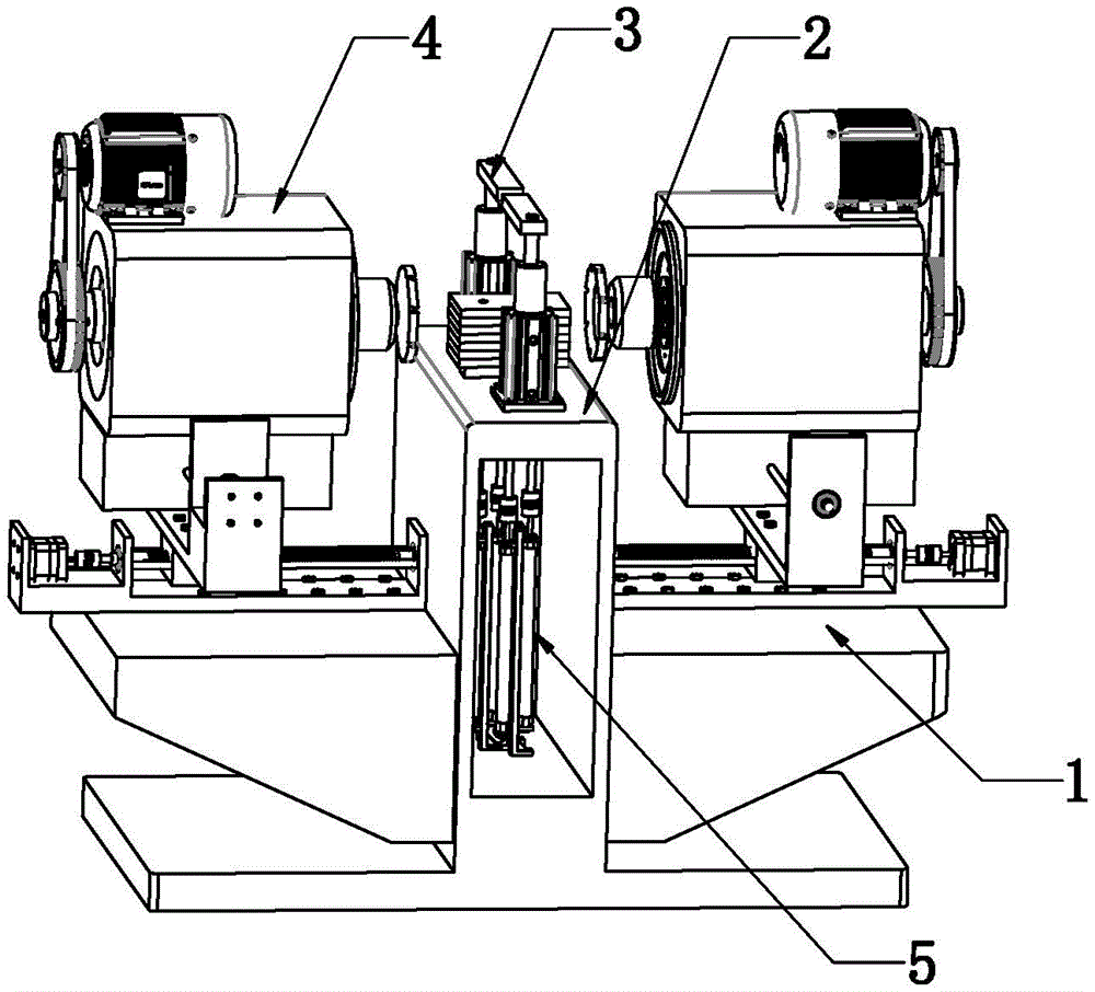
Special device for processing four side surfaces of wearing plate
Technical Field
The utility model relates to a nylon plate part processing device, in particular to a special device for processing four side surfaces of a wear plate.
Background
For the machining of nylon plate parts, traditionally, single machine tools are mainly machined one by one, the existing machining mode causes high labor intensity and low production efficiency, and then, in order to improve the production efficiency, some assembly line operation modes appear on the market, but the assembly line operation is only limited to the machining of a single process, and along with the development requirement of enterprises on the integration of the whole process flow, the mode can not adapt to the development requirement, especially, for the machining of the side surfaces of the parts, the surfaces needing milling are more, in the prior art, a plurality of milling devices are generally needed to be respectively machined, so that the machining time of the process is long, workpieces are required to be continuously clamped in the working process, the labor intensity is high, the parts are difficult to be integrated into the integrated production process flow, and finally, the milling machining of the side surfaces is hard to be combined into an automatic assembly line, however, the efficiency of the machining process is far lower than that of other processes, so that the working efficiency is not improved, but the efficiency of the whole assembly line operation is reduced, and in addition, the conventional milling has the problems of poor positioning reliability, easy influence on milling precision, even product scrapping and the like.
Disclosure of Invention
The utility model aims to solve the technical problem of providing a special device for processing the four side surfaces of the wear plate, which has the advantages of ingenious structural design and reliable positioning, thereby ensuring the processing precision and improving the production efficiency.
In order to solve the technical problem, the special device for machining the four side surfaces of the wear plate comprises a machine body, wherein an operation table for milling a workpiece is arranged on the machine body, a pair of pressing and holding devices for pressing the workpiece is arranged on the operation table, a rotary air cylinder is arranged in the operation table, a rotary plate which is matched with the rotary air cylinder is arranged on the operation table, the workpiece can be stacked on the rotary plate and driven by the rotary air cylinder to rotate under the driving of the rotary plate to adjust the machining direction, two pairs of air pressure devices are arranged below the operation table, lifting columns of the two pairs of air pressure devices can be selectively inserted into through holes of the stacked workpiece, a pair of side surface milling devices which are vertically arranged with the pair of pressing and holding devices is arranged on two side surfaces of the operation table, and the side surface milling devices can mill the workpiece pressed by the pressing and holding devices.
The air pressure device comprises a fixedly arranged air cylinder seat, a stacking air cylinder arranged on the air cylinder seat and a lifting column connected to the stacking air cylinder through a coupler.
The side milling device comprises a longitudinal lead screw transmission mechanism, a transverse lead screw transmission mechanism and a milling part arranged on the transverse lead screw transmission mechanism, wherein the transverse lead screw transmission mechanism is arranged on the longitudinal lead screw transmission mechanism through a sliding block and can longitudinally move under the driving of the longitudinal lead screw transmission mechanism, and the milling part is arranged on the transverse lead screw transmission mechanism through a sliding seat and can transversely move under the driving of the transverse lead screw transmission mechanism.
The milling part comprises a horizontal spindle arranged on the sliding seat, a spindle motor arranged above the horizontal spindle and a milling cutter arranged on the horizontal spindle.
The feeding side of the lathe bed is provided with a feeding transfer table, and the discharging side of the lathe bed is provided with a discharging transfer table.
The feeding transfer table is provided with a feeding manipulator used for stacking workpieces on the feeding transfer table to operate, and the discharging transfer table is provided with a discharging manipulator used for outputting the workpieces on the feeding transfer table.
The lathe bed is convex style of calligraphy structure, and the bellying face of lathe bed is as the operation panel.
The utility model has the advantages that:
(1) the through holes machined by the workpieces are directly positioned through the air cylinder device, and then the two side faces are milled through the two side face milling devices, so that the plurality of workpieces can be stacked firstly, and then the side faces are integrally end-milled, stacked workpieces are subjected to stacking multi-face processing, the production takt is greatly shortened, and the working efficiency is greatly improved.
(2) Through be provided with revolving cylinder in the operation panel and set up the commentaries on classics board of installing with revolving cylinder cooperation on the operation panel, make the work piece pile up on changeing the board and by revolving cylinder drive rotatory 90 under the drive of commentaries on classics board and carry out two other side processing from this, realized that an equipment carries out the processing on all surfaces to many work pieces from this, saved the time that the clamping was said to consume repeatedly in the traditional course of working, still further improved machining efficiency when having reduced intensity of labour.
(3) The unified processing of all the side surfaces of a plurality of unified workpieces on the same equipment can be integrated into an integrated production process flow and effectively linked with other procedures, and the efficiency of the whole assembly line operation is greatly improved.
(4) Through the cooperation of the pressing and holding device, the air pressure device and the like, the positioning is reliable in the machining process, the machining precision is greatly improved, the product quality is ensured, the two side edges are horizontally and clockwise rotated to stack the workpieces for 90 degrees after being milled, the other two side edges are directly end-milled again, the re-clamping time is saved, the process balance is optimized, and the production efficiency is improved.
Drawings
FIG. 1 is a schematic perspective view of a special device for machining four side surfaces of a wear plate according to the present invention;
FIG. 2 is a schematic structural view of the special device for machining four side surfaces of the wear plate according to the present invention;
FIG. 3 is a schematic structural diagram of a lathe bed removal device for machining four side surfaces of a wear plate according to the present invention;
fig. 4 is an enlarged schematic view of a portion a of fig. 3.
Detailed Description
The following describes the special device for machining four sides of the wear plate in detail with reference to the accompanying drawings and the detailed description.
As shown in the figures, the special device for processing four side surfaces of the wear plate comprises a machine body 1 with a convex structure, wherein the convex surface of the machine body 1 is used as an operation table for milling a workpiece 6, a pair of pressing devices 3 for pressing the workpiece is arranged on the operation table 2, a rotating cylinder 7 is arranged in the operation table 2, a rotating plate 8 which is matched with the rotating cylinder 7 is arranged on the operation table 2, the rotating plate extends out of the machine body for a certain height and does not interfere with the machine body when rotating, the workpiece 6 can be stacked on the rotating plate 8 and is driven by the rotating cylinder to rotate by 90 degrees under the driving of the rotating plate, so that the processing direction is adjusted, and a plurality of side surfaces can be processed, namely, the rotating cylinder drives the workpiece on the rotating plate to rotate clockwise by 90 degrees horizontally, so that the other two side surfaces can be end milled; two pairs of air pressure devices 5 which are symmetrically arranged front and back and left and right are arranged below the operating platform 2, and as can be seen from the figure, the two air pressure devices 5 respectively comprise a fixedly arranged air cylinder seat 9, a stacking air cylinder 11 arranged on the air cylinder seat and a lifting column 13 connected to the stacking air cylinder through a coupler 12, the air cylinder seat 9 is fixedly connected to a support, the support is fixed in the machine body through a bolt, the lifting columns of the two pairs of air pressure devices 5 can be selectively inserted into through holes of stacked workpieces 6, the lifting columns extend out of the machine body for a certain initial height and are used for positioning the stacked workpieces, and the compressing devices on the two sides clamp the stacked workpieces; the left side and the right side (the direction shown in fig. 2) of the operating platform 2 are provided with a pair of side milling devices 4 which are arranged perpendicular to the pair of pressing devices, that is, the two side milling devices 4 are symmetrically arranged on the left side and the right side of the operating platform 2 and are arranged perpendicular to the two pressing devices, when in processing, front-back pressing is realized, the left side and the right side are simultaneously milled, and the side milling devices 4 can mill a workpiece pressed by the pressing devices 3.
Further, the side milling device 4 includes a longitudinal screw transmission mechanism 10, a transverse screw transmission mechanism 14 and a milling part installed on the transverse screw transmission mechanism, the transverse screw transmission mechanism 14 is installed on the longitudinal screw transmission mechanism through a slide block 15 and can be driven by the longitudinal screw transmission mechanism to move longitudinally, the milling part is installed on the transverse screw transmission mechanism through a slide base 16 and can move transversely under the drive of the transverse screw transmission mechanism, for the longitudinal screw transmission mechanism 10, the side milling device includes a longitudinal base body, a longitudinal guide rail motor arranged at the left end of the longitudinal base body, a longitudinal ball screw arranged on the longitudinal base body and two longitudinal linear guide rails arranged in parallel on two sides of the longitudinal ball screw, the slide blocks 15 are installed on the longitudinal linear guide rails and the longitudinal ball screw, the slide blocks 15 are provided with transverse grooves, a transverse groove, the milling part comprises a horizontal main shaft 17 arranged on a sliding seat 16, a main shaft motor 18 arranged above the horizontal main shaft 17 and a milling cutter 19 arranged on the horizontal main shaft, and as can be seen from the figure, the main shaft motor drives the horizontal main shaft to do rotary motion through a belt so as to drive a cutter at the front end of the horizontal main shaft to do cutting motion.
Furthermore, the feeding side of the lathe bed 1 is provided with a feeding transfer table, the discharging side of the lathe bed 1 is provided with a discharging transfer table, the feeding transfer table is provided with a feeding manipulator used for stacking the workpieces on the feeding transfer table to operate, and the discharging transfer table is provided with a discharging manipulator used for outputting the workpieces on the discharging transfer table.
The working principle is as follows:
after the workpieces are clamped, milling devices on the left side and the right side of the lathe bed mill two side surfaces of the stacked workpieces, after milling is completed, the lifting column descends to return into the lathe bed, the rotating cylinder drives the rotating plate to rotate clockwise and horizontally by 90 degrees, the lifting column ascends again to position the stacked workpieces, the pressing devices on the front side and the rear side clamp the stacked workpieces, and the milling devices on the left side and the right side of the lathe bed mill the other two side surfaces of the stacked workpieces; and after the milling is finished, taking the machined stacked workpieces away by the transfer manipulator and placing the stacked workpieces to a specified position.
It is to be understood that the above description is not intended to limit the present invention, and the present invention is not limited to the above examples, and those skilled in the art may make modifications, alterations, additions or substitutions within the spirit and scope of the present invention.