CN215943609U - A starter electromagnetic switch mold - Google Patents

A starter electromagnetic switch mold Download PDF

Info

Publication number
CN215943609U
CN215943609U CN202122004097.1U CN202122004097U CN215943609U CN 215943609 U CN215943609 U CN 215943609U CN 202122004097 U CN202122004097 U CN 202122004097U CN 215943609 U CN215943609 U CN 215943609U
Authority
CN
China
Prior art keywords
fixedly connected
spring
electromagnetic switch
rod
fixed box
Prior art date
Legal status (The legal status is an assumption and is not a legal conclusion. Google has not performed a legal analysis and makes no representation as to the accuracy of the status listed.)
Expired - Fee Related
Application number
CN202122004097.1U
Other languages
Chinese (zh)
Inventor
边文静
沈建芬
刘珈妤
Current Assignee (The listed assignees may be inaccurate. Google has not performed a legal analysis and makes no representation or warranty as to the accuracy of the list.)
Zhejiang Tengxiang Auto Parts Co ltd
Original Assignee
Wuxi Xixing Automobile Electric Appliance Co ltd
Priority date (The priority date is an assumption and is not a legal conclusion. Google has not performed a legal analysis and makes no representation as to the accuracy of the date listed.)
Filing date
Publication date
Application filed by Wuxi Xixing Automobile Electric Appliance Co ltd filed Critical Wuxi Xixing Automobile Electric Appliance Co ltd
Priority to CN202122004097.1U priority Critical patent/CN215943609U/en
Application granted granted Critical
Publication of CN215943609U publication Critical patent/CN215943609U/en
Expired - Fee Related legal-status Critical Current
Anticipated expiration legal-status Critical

Links

Images

Landscapes

  • Molds, Cores, And Manufacturing Methods Thereof (AREA)

Abstract

本实用新型一种起动机电磁开关模具,包括:底座,底座顶部螺栓连接有支撑架,支撑架一端固定连接有步进电机,步进电机输出端固定连接有转动轴,转动轴远离步进电机一端固定连接有固定箱,固定箱内部均匀开设有冷却腔,冷却腔内部固定连接有风扇,本实用新型具有以下优点:通过使用电机带动固定箱转动,便于倒模时使用;通过使用承接槽承接零部件,使用第二弹簧减少承接槽的震动,通过使用限位块夹持在固定箱两端,防止其在注料时,防止固定箱转动,影响零部件的成型,通过使用风扇带动进气,使得空气带走热量,便于凹模的降温。

Figure 202122004097

The utility model relates to a starter electromagnetic switch mold, comprising: a base, a support frame is connected with bolts on the top of the base, one end of the support frame is fixedly connected with a stepping motor, an output end of the stepping motor is fixedly connected with a rotating shaft, and the rotating shaft is far away from the stepping motor A fixed box is fixedly connected at one end, a cooling cavity is evenly opened inside the fixed box, and a fan is fixedly connected inside the cooling cavity. For parts, the second spring is used to reduce the vibration of the receiving groove, and the limit blocks are used to clamp the two ends of the fixed box to prevent the fixed box from rotating during injection, which affects the molding of the parts, and the fan is used to drive the air intake. , so that the air takes away the heat, which is convenient for the cooling of the die.

Figure 202122004097

Description

Electromagnetic switch die of starter
Technical Field
The utility model discloses starter equipment technical field, concretely relates to starter electromagnetic switch mould.
Background
The mould is a main tool for injection moulding, forging and stamping production modes, and different parts are manufactured into moulds with inner cavities in different shapes, and plastic materials can be put into the moulds to manufacture blanks for forming the parts.
The cooling effect of the existing starter electromagnetic switch mold is poor, the existing device is not easy to take out parts, the part receiving groove is easy to be impacted by blanks, the device is damaged, and the injection molding of the female mold in the device is easy to be affected due to external vibration, so that the quality of the parts is affected.
SUMMERY OF THE UTILITY MODEL
The utility model aims to solve the technical problems that the cooling effect of the existing starter electromagnetic switch die is poor, and the starter electromagnetic switch die is convenient to use during die reversing by using a motor to drive a fixed box to rotate, and brings hot air in the device away to be discharged through an air outlet by using a fan to drive the air inlet, so that the cooling of a female die is facilitated.
The technical scheme adopted by the utility model for solving the technical problem is as follows: a starter electromagnetic switch die, comprising: the base, base top bolted connection has the support frame, support frame one end fixedly connected with step motor, step motor output fixedly connected with axis of rotation, step motor one end fixedly connected with fixed case is kept away from to the axis of rotation, the cooling chamber has evenly been seted up to fixed incasement portion, the inside fixedly connected with fan in cooling chamber.
According to a preferable technical scheme, the air inlets and the air outlets are uniformly formed in two ends of the fixed box, the first sliding rod is fixedly connected to two ends of an inner cavity of the fixed box, the first spring is sleeved on the first sliding rod, the concave die is fixedly connected to the first spring, and when the die is reversed, the concave die drives the first spring to move, so that the concave die vibrates along the first sliding rod, and parts can be conveniently moved out.
According to a preferred technical scheme, the supporting plate is fixedly connected to the top of the supporting frame, the hydraulic rod is fixedly connected to the middle of the top of the supporting plate, the output end of the bottom of the hydraulic rod penetrates through one end of the supporting plate and is fixedly connected with the male die, the feeding hole is formed in one end of the top of the male die, and the hydraulic rod drives the male die to move, so that the male die extrudes the female die and the female die is prevented from moving.
As a preferred technical scheme of the utility model, an inner cavity at the top of the base is fixedly connected with an electric push rod, an inner cavity at the output end of the top of the electric push rod is fixedly connected with a second spring, the top of the second spring is fixedly connected with a movable rod, the top of the movable rod penetrates through one end of the electric push rod and is fixedly connected with a bearing groove, the movable rod is driven by the electric push rod to move, so that the bearing groove is supported by the movable rod to move up and down, the vibration of the bearing groove is reduced by the second spring, and the impact between a part and the bearing groove is reduced.
According to a preferable technical scheme, the bottom of the inner cavity of the bearing groove is provided with two movable grooves, the bearing groove is fixedly connected with a second sliding rod through the movable grooves, two ends of the second sliding rod are both connected with limiting blocks in a sliding mode, a third spring is fixedly connected between the two limiting blocks, and the fixed box can be clamped through the limiting blocks, so that the fixed box is prevented from rotating to influence the forming of parts when the fixed box is injected.
The utility model has the following advantages: the fixed box is driven to rotate by the motor, so that the mould is convenient to use when the mould is reversed; accept the groove through using and accept spare part, use the vibrations that the groove was accepted in the reduction of second spring, through using the stopper centre gripping at fixed case both ends, prevent that it from when annotating the material, prevent that fixed case from rotating, influence the shaping of spare part, drive through using the fan and admit air for the heat is taken away to the air, the cooling of the die of being convenient for.
Drawings
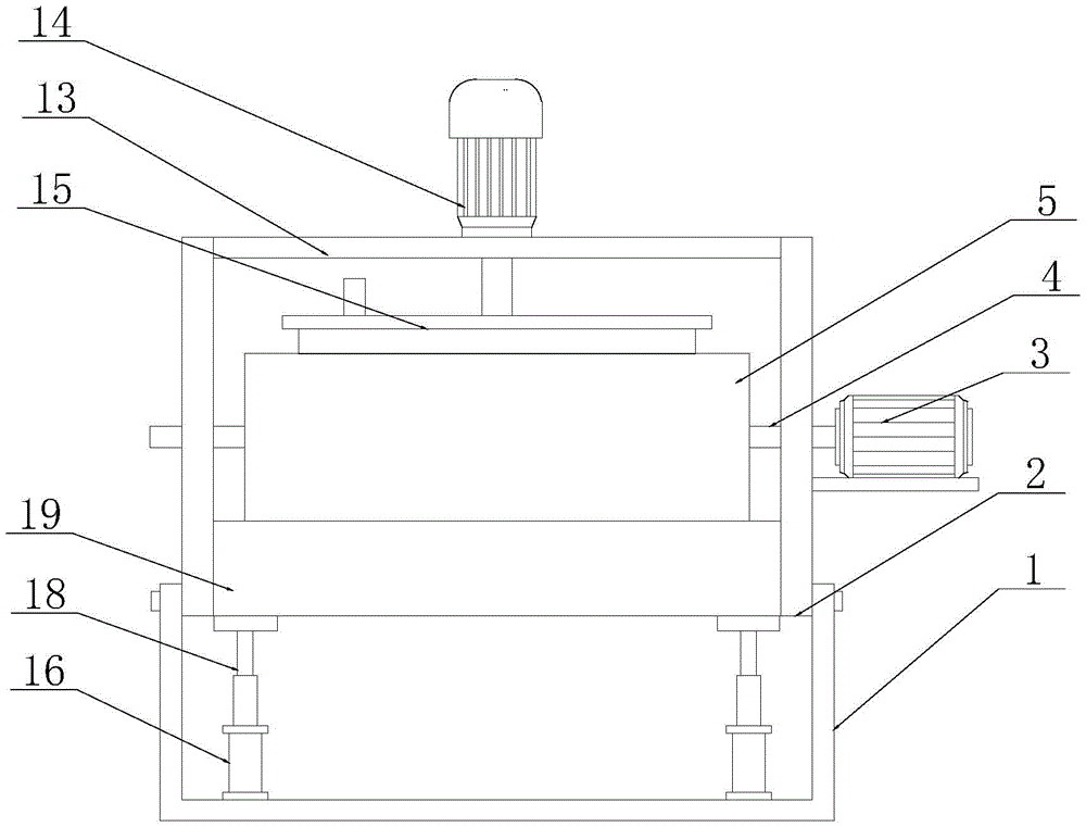
Fig. 1 is a schematic front structural view of a starter electromagnetic switch die according to a preferred embodiment of the utility model;
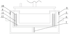
FIG. 2 is a schematic cross-sectional view of a stationary box of a starter electromagnetic switch die according to a preferred embodiment of the utility model;
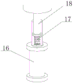
fig. 3 is a schematic structural view of a front cross section of an electric push rod of a starter electromagnetic switch die according to a preferred embodiment of the utility model;
fig. 4 is a schematic front sectional structural view of a receiving groove of a starter electromagnetic switch die according to a preferred embodiment of the utility model.
Description of reference numerals: 1. a base; 2. a support frame; 3. a stepping motor; 4. a rotating shaft; 5. a fixed box; 6. a cooling chamber; 7. a fan; 8. an air inlet; 9. an air outlet; 10. a first slide bar; 11. a first spring; 12. a female mold; 13. a support plate; 14. a hydraulic lever; 15. a male die; 16. an electric push rod; 17. a second spring; 18. a movable rod; 19. a receiving groove; 20. a movable rod; 21. a third spring; 22. and a limiting block.
Detailed Description
The technical scheme of the utility model is clearly and completely described in the following with reference to the accompanying drawings. In the description of the present invention, it should be noted that the terms "center", "upper", "lower", "left", "right", "vertical", "horizontal", "inner", "outer", etc., indicate orientations or positional relationships based on the orientations or positional relationships shown in the drawings, and are only for convenience of description and simplicity of description, but do not indicate or imply that the device or element being referred to must have a particular orientation, be constructed and operated in a particular orientation, and thus, should not be construed as limiting the present invention. Furthermore, the terms "first," "second," and "third" are used for descriptive purposes only and are not to be construed as indicating or implying a relative importance.
In the description of the present invention, it should be noted that, unless otherwise explicitly specified or limited, the terms "mounted," "connected," and "connected" are to be construed broadly, e.g., as meaning either a fixed connection, a removable connection, or an integral connection; can be mechanically or electrically connected; they may be connected directly or indirectly through intervening media, or they may be interconnected between two elements. The specific meanings of the above terms in the present invention can be understood in specific cases to those skilled in the art.
The utility model will be further explained with reference to the drawings.
Referring to fig. 1-4, the present invention provides a starter electromagnetic switch mold, including: base 1, 1 top bolted connection of base has support frame 2, 2 one end fixedly connected with step motor 3 of support frame, the support and the fixing of the device of being convenient for, step motor 3 output end fixedly connected with axis of rotation 4, 3 one end fixedly connected with stationary box 5 of step motor are kept away from to axis of rotation 4, it is rotatory to drive axis of rotation 4 through step motor 3, make stationary box 5 rotate, be convenient for its upset, the help takes out spare part, cooling chamber 6 has evenly been seted up to stationary box 5 inside, the inside fixedly connected with fan 7 in cooling chamber 6, it flows to drive the air through fan 7, enter into cooling chamber 6, be convenient for concave mould 12's heat dissipation and cooling.
Wherein, one end of the fixed box 5 is uniformly and fixedly provided with an air inlet 8, one end of the cooling cavity 6, which is far away from the air inlet 8, is provided with an air outlet 9, so that air can conveniently enter the air inlet 8, the air is driven by a fan 7 fixedly connected inside the cooling cavity 6 to flow and is discharged from the air outlet 9, so that heat dissipation is convenient, two ends inside the fixed box 5 are fixedly connected with first slide bars 10, the tops of the two first slide bars 10 are both slidably connected with a concave die 12, the bottom of the concave die 12 is fixedly connected with a first spring 11, the first spring 11 is sleeved on the first slide bar 10, the first spring 11 is pulled after the concave die 12 is turned over, so that the concave die 12 vibrates, and the discharge of parts is convenient,
wherein, the female die 12 is clamped with the male die 15, the top of the male die 15 is fixedly connected with an output end of a hydraulic rod 14, the bottom of the hydraulic rod 14 is fixedly connected with a support plate 13, two ends of the support plate 13 are respectively and fixedly connected in the middle of a support frame 2, the hydraulic rod 14 drives the male die 15 to move, so as to facilitate the forming of parts, a bearing groove 19 is slidably connected between the support frames 2, a second slide rod 20 is fixedly connected inside the bearing groove 19, a third spring 21 is sleeved on the second slide rod 20, two ends of the third spring 21 are both fixedly connected with a limit block 22, the limit block 22 is in a trapezoidal structure, the limit block 22 is driven to move by the third spring 21, so as to be conveniently clamped at two ends of the fixed box 5, so as to facilitate the limit of the fixed box 5, the bottom of the bearing groove 19 is fixedly connected with a movable rod 18, the bottom of the movable rod 18 is fixedly connected with a second spring 17, and the bottom of the second spring 17 is fixedly connected with an electric push rod 16, the electric push rod 16 drives the movable rod 18 to move, so that the height of the receiving groove 19 is convenient to change, and the vibration of the receiving groove 19 is reduced through the second spring 17.
Specifically, firstly, the electric push rod 16 is opened to drive the bearing groove 19 to move upwards, so that the limiting blocks 22 slidably connected inside the bearing groove 19 move, the limiting blocks 22 are clamped at two ends of the fixed box 5, the limiting blocks 22 are extruded to move through the third spring 21, the fixed box 5 is convenient to fix, then the hydraulic rod 14 is opened to move, the male die 15 is movably inserted into the female die 12, the female die 12 is conveniently fed through the feed inlet fixedly connected with one end of the female die 12, raw materials are conveyed to the die, then the fan 7 is opened to drive the air to enter from the air inlet 8, so that the heat of the female die 12 is taken away by the air, the heat dissipation of parts is convenient, then the electric push rod 16 is opened, so that the limiting blocks 22 inside the bearing groove 19 are not clamped at two ends of the fixed box 5, at the moment, the stepping motor 3 is opened, the fixed box 5 fixedly connected with the middle of the rotating shaft 4 is driven to rotate, so that the female die 12 moves along the first slide rod 10, the first spring 11 is pulled to move, so that vibration of the female die 12 is facilitated, the poured parts are helped to enter the receiving groove 19, the receiving groove 19 extrudes the movable rod 18, the movable rod 18 extrudes the second spring 17 to vibrate, and impact vibration damage is prevented.
The foregoing is only a preferred embodiment of the present invention, and it should be noted that those skilled in the art can make various improvements and modifications without departing from the principle of the present invention, and these improvements and modifications should also be construed as the protection scope of the present invention.
Other parts of the utility model not described in detail are prior art and are not described in detail herein.
Finally, it should be noted that: the above embodiments are only used to illustrate the technical solution of the present invention, and not to limit the same; while the utility model has been described in detail and with reference to the foregoing embodiments, it will be understood by those skilled in the art that: the technical solutions described in the foregoing embodiments may still be modified, or some or all of the technical features may be equivalently replaced; and the modifications or the substitutions do not make the essence of the corresponding technical solutions depart from the scope of the technical solutions of the embodiments of the present invention.

Claims (5)

1.一种起动机电磁开关模具,其特征在于,包括:底座(1),所述底座(1)顶部螺栓连接有支撑架(2),所述支撑架(2)一端固定连接有步进电机(3),所述步进电机(3)输出端固定连接有转动轴(4),所述转动轴(4)远离步进电机(3)一端固定连接有固定箱(5),所述固定箱(5)内部均匀开设有冷却腔(6),所述冷却腔(6)内部固定连接有风扇(7)。1. A starter electromagnetic switch mold, characterized in that it comprises: a base (1), the top of the base (1) is bolted with a support frame (2), and one end of the support frame (2) is fixedly connected with a stepping A motor (3), a rotating shaft (4) is fixedly connected to the output end of the stepping motor (3), and a fixing box (5) is fixedly connected to one end of the rotating shaft (4) away from the stepping motor (3). A cooling cavity (6) is evenly opened inside the fixing box (5), and a fan (7) is fixedly connected inside the cooling cavity (6). 2.如权利要求1所述的一种起动机电磁开关模具,其特征在于,所述固定箱(5)两端均匀开设有进气口(8)和出气口(9),所述固定箱(5)内腔两端均固定连接有第一滑杆(10),所述第一滑杆(10)上套有第一弹簧(11),所述第一弹簧(11)上固定连接有凹模具(12)。2. A starter electromagnetic switch mold according to claim 1, characterized in that, both ends of the fixed box (5) are evenly provided with an air inlet (8) and an air outlet (9). (5) Both ends of the inner cavity are fixedly connected with a first sliding rod (10), a first spring (11) is sleeved on the first sliding rod (10), and a first spring (11) is fixedly connected with Concave mold (12). 3.如权利要求1所述的一种起动机电磁开关模具,其特征在于,所述支撑架(2)顶部固定连接有支撑板(13),所述支撑板(13)顶部中间固定连接有液压杆(14),所述液压杆(14)底部输出端穿过支撑板(13)一端固定连接有凸模(15),所述凸模(15)顶部一端开设有进料口。3. A starter electromagnetic switch mold according to claim 1, wherein a support plate (13) is fixedly connected to the top of the support frame (2), and a middle of the top of the support plate (13) is fixedly connected with A hydraulic rod (14), the bottom output end of the hydraulic rod (14) is fixedly connected with a punch (15) through one end of the support plate (13), and a feed port is provided at one end of the top of the punch (15). 4.如权利要求1所述的一种起动机电磁开关模具,其特征在于,所述底座(1)顶部内腔固定连接有电动推杆(16),所述电动推杆(16)顶部输出端内腔固定连接有第二弹簧(17),所述第二弹簧(17)顶部固定连接有活动杆(18),所述活动杆(18)顶部穿过电动推杆(16)一端固定连接有承接槽(19)。4. A starter electromagnetic switch mold according to claim 1, characterized in that, an electric push rod (16) is fixedly connected to the top inner cavity of the base (1), and the top of the electric push rod (16) outputs an output The inner cavity of the end is fixedly connected with a second spring (17), the top of the second spring (17) is fixedly connected with a movable rod (18), and the top of the movable rod (18) is fixedly connected with one end of the electric push rod (16). There is a receiving groove (19). 5.如权利要求4所述的一种起动机电磁开关模具,其特征在于,所述承接槽(19)内腔底部开设有两个活动槽,所述承接槽(19)通过活动槽固定连接有第二滑杆(20),所述第二滑杆(20)两端均滑动连接有限位块(22),两个所述限位块(22)之间固定连接有第三弹簧(21)。5. A starter electromagnetic switch mold according to claim 4, characterized in that, two movable grooves are opened at the bottom of the inner cavity of the receiving groove (19), and the receiving groove (19) is fixedly connected through the movable grooves There is a second sliding rod (20), both ends of the second sliding rod (20) are slidably connected to limit blocks (22), and a third spring (21) is fixedly connected between the two limit blocks (22). ).
CN202122004097.1U 2021-08-24 2021-08-24 A starter electromagnetic switch mold Expired - Fee Related CN215943609U (en)

Priority Applications (1)

Application Number Priority Date Filing Date Title
CN202122004097.1U CN215943609U (en) 2021-08-24 2021-08-24 A starter electromagnetic switch mold

Applications Claiming Priority (1)

Application Number Priority Date Filing Date Title
CN202122004097.1U CN215943609U (en) 2021-08-24 2021-08-24 A starter electromagnetic switch mold

Publications (1)

Publication Number Publication Date
CN215943609U true CN215943609U (en) 2022-03-04

Family

ID=80433869

Family Applications (1)

Application Number Title Priority Date Filing Date
CN202122004097.1U Expired - Fee Related CN215943609U (en) 2021-08-24 2021-08-24 A starter electromagnetic switch mold

Country Status (1)

Country Link
CN (1) CN215943609U (en)

Cited By (1)

* Cited by examiner, † Cited by third party
Publication number Priority date Publication date Assignee Title
CN118874879A (en) * 2024-09-27 2024-11-01 常州协和光电器件有限公司 A testing mechanism for bending resistance of automobile taillight circuit board

Cited By (1)

* Cited by examiner, † Cited by third party
Publication number Priority date Publication date Assignee Title
CN118874879A (en) * 2024-09-27 2024-11-01 常州协和光电器件有限公司 A testing mechanism for bending resistance of automobile taillight circuit board

Similar Documents

Publication Publication Date Title
CN111231214A (en) Multi-station synchronous injection molding device
CN214773607U (en) An injection mold for auto parts with jacking function
CN107901344B (en) Injection mold capable of rapidly and efficiently demolding and injection molding method thereof
CN113997528A (en) Injection mold for precise electric tool shell and production process
CN210361806U (en) Hydraulic hard-plastic molding sintered brick making machine
CN218256487U (en) Turbine blade injection molding mould convenient to open
CN216732874U (en) Injection molding drawing of patterns frock
CN216300042U (en) Demoulding structure of injection moulding mould
CN116476311A (en) Batch injection molding device for automobile parts
CN215283003U (en) Compression molding device convenient for exhaust for production of automobile rubber parts
CN213728898U (en) Light alloy stamping die convenient to ejection of compact
CN213533679U (en) High-efficient injection moulding machine
CN213618134U (en) Shell injection molding material taking device with inserts
CN211683317U (en) Injection mold with ejection device
CN212241947U (en) Refrigerator is with freezing trim shaping injection mold down
CN219055243U (en) Injection mold with micro-distance adjusting stability is strong
CN222590552U (en) Efficient injection mold
CN215969828U (en) A mobile injection mold with automatic unthreading
CN222077771U (en) A quick-change mold base for composite molds
CN220242277U (en) Mould for forming precise plastic gear
CN219902569U (en) Crucible mould swage forming device
CN222448222U (en) A feeding gate structure for die-casting mold of mobile phone middle plate
CN214562542U (en) Quick demoulding's mould for shell
CN222168912U (en) Mould for manufacturing commutator reinforcing ring
CN215619642U (en) Mould that lemon slicer drops into container

Legal Events

Date Code Title Description
GR01 Patent grant
GR01 Patent grant
TR01 Transfer of patent right

Effective date of registration: 20230823

Address after: No. 4 Guangming Road, Hai'an Haiguang Industrial Zone, Tangxia Town, Rui'an City, Wenzhou City, Zhejiang Province, 325000

Patentee after: Zhejiang TengXiang Auto Parts Co.,Ltd.

Address before: 214000 Yuqi supporting area (Qibei Road), Huishan Economic Development Zone, Wuxi City, Jiangsu Province

Patentee before: Wuxi Xixing Automobile Electric Appliance Co.,Ltd.

CF01 Termination of patent right due to non-payment of annual fee

Granted publication date: 20220304