Display stand for industrial design
Technical Field
The utility model relates to the technical field of industrial design, in particular to a display stand for industrial design.
Background
The display cabinet is a display platform which is provided for commodity display and has a protection function. The display cabinet is a main carrier for displaying commodities in businesses and also a main frame for forming the visual sense of a business space. Different products have different display cabinet forms and functions. The market show cabinet design and manufacture will directly affect the sale of goods and the brand image of enterprises, not only need to take and put clothes, the practicality of furnishing articles and artworks as much as possible, but also need to have affinity and individuality.
At present, the common show stand adopts comparatively simple structure to demonstrate the showpiece mostly among the industrial design, and this kind of show stand ubiquitous bandwagon effect is relatively poor, can not adjust the size according to the showpiece and lead to space utilization lower, also has the staff of not being convenient for simultaneously and removes and fixed shortcoming to the show stand.
SUMMERY OF THE UTILITY MODEL
To solve the problems set forth in the background art described above. The utility model provides a display stand for industrial design, which has the functions of lifting, moving, rotating and adjusting and solves the problems of poor display effect, low space utilization rate and convenience.
In order to achieve the purpose, the utility model adopts the following technical scheme:
the display stand for industrial design comprises an installation stand, wherein a supporting seat is arranged in the middle of the upper surface of the installation stand, an angle adjusting assembly for enabling the supporting seat to generate angular displacement is fixedly arranged between the supporting seat and the installation stand, a plurality of placing stands are fixedly arranged on the upper surface of the supporting seat, a plurality of lifting adjusting assemblies are fixedly arranged among the placing stands, each lifting adjusting assembly comprises a supporting sleeve, the supporting sleeve is fixedly connected with the upper surface of the placing stand, a plurality of limiting grooves are formed in the inner wall of the supporting sleeve in an equiangular mode, a threaded lead screw is sleeved on the inner wall of the supporting sleeve, a plurality of limiting blocks corresponding to the limiting grooves are fixedly arranged on one side of the surface of the threaded lead screw in an equiangular mode, one end of the threaded lead screw is fixedly connected with the lower surface of the placing stand, an internal thread adjusting sleeve is rotatably connected to the top of the supporting sleeve, and the inner wall of the internal thread adjusting sleeve is in threaded connection with the threaded lead screw, the lower fixed surface of mount table is equipped with the installation base, the both sides of installation base inner wall are all fixed and are equipped with the guide post, two guide post sliding connection is equipped with the lifter plate, the both sides of lifter plate upper surface are all fixed and are equipped with two fixed blocks, the fixed block is all rotated and is connected and be equipped with the connecting plate, one side that the fixed block was kept away from to the connecting plate is all rotated and is connected and be equipped with the movable block, and the movable block all with the top sliding connection of installation base inner wall, the fixed drive assembly that makes the movable block produce the displacement that is equipped with of installation base, the lower fixed surface of lifter plate is equipped with four universal wheels, the lower surface of installation base is equipped with four through holes corresponding with the universal wheel.
Preferably, the angle adjusting component comprises a motor, the motor is fixedly connected with the bottom of the inner wall of the mounting table, a first worm is fixedly arranged on an output shaft of the motor, a first worm wheel is connected to one side of the first worm in a toothed manner, a supporting column is fixedly arranged on the first worm wheel, one end of the supporting column is rotatably connected with the bottom of the inner wall of the mounting table, and one end, far away from the first worm wheel, of the supporting column penetrates through the mounting table and is fixedly connected with the supporting seat.
Preferably, the driving assembly comprises a transmission column, the transmission column is connected with the inner wall of the installation base in a rotating mode, a second worm is fixedly arranged on two sides of the surface of the transmission column, a second worm wheel is arranged on one side of the second worm in a toothed connection mode, a double-thread lead screw is fixedly arranged on the second worm wheel, two ends of the double-thread lead screw are rotatably connected with the inner wall of the installation base, the double-thread lead screw is respectively connected with the moving block in a threaded mode, one end of the transmission column penetrates through the installation base and is fixedly provided with an adjusting disc, and a rocker arm is rotatably connected to one side of the adjusting disc.
Preferably, pull rings are fixedly arranged on two sides of the upper surface of the mounting platform, and two storage drawers are inserted into one side of the mounting platform.
Preferably, the placing table is arranged from bottom to top in a diameter from large to small, and a plurality of anti-slip strips are fixedly arranged on the upper surface of the placing table.
Preferably, a controller is fixedly arranged on one side of the mounting table.
Compared with the prior art, the utility model has the beneficial effects that: the supporting seat drives the placing table and the lifting adjusting assembly to start rotating under the driving of the angle adjusting assembly, so that the exhibits rotate, a viewer can conveniently watch the exhibits in all directions at one angle, the ornamental effect is improved, the distance between two adjacent placing tables can be adjusted according to needs under the matching of the lifting adjusting assembly, the exhibits with different sizes can be conveniently placed, the application range is wide, the lifting plate drives the universal wheels to start moving up and down under the driving of the driving assembly, the display moving and fixing device is convenient to move and fix, the stabilizing effect is good, the storage drawers are arranged, workers can conveniently store and store the exhibits, the workers can conveniently move the display moving device under the action of the pull ring, and the phenomenon that the exhibits fall off from the placing tables during rotation can be avoided under the action of the anti-slip strips.
The parts of the device not involved are the same as or can be implemented using prior art.
Drawings
The accompanying drawings, which are included to provide a further understanding of the utility model and are incorporated in and constitute a part of this specification, illustrate embodiments of the utility model and together with the description serve to explain the principles of the utility model and not to limit the utility model. In the drawings:
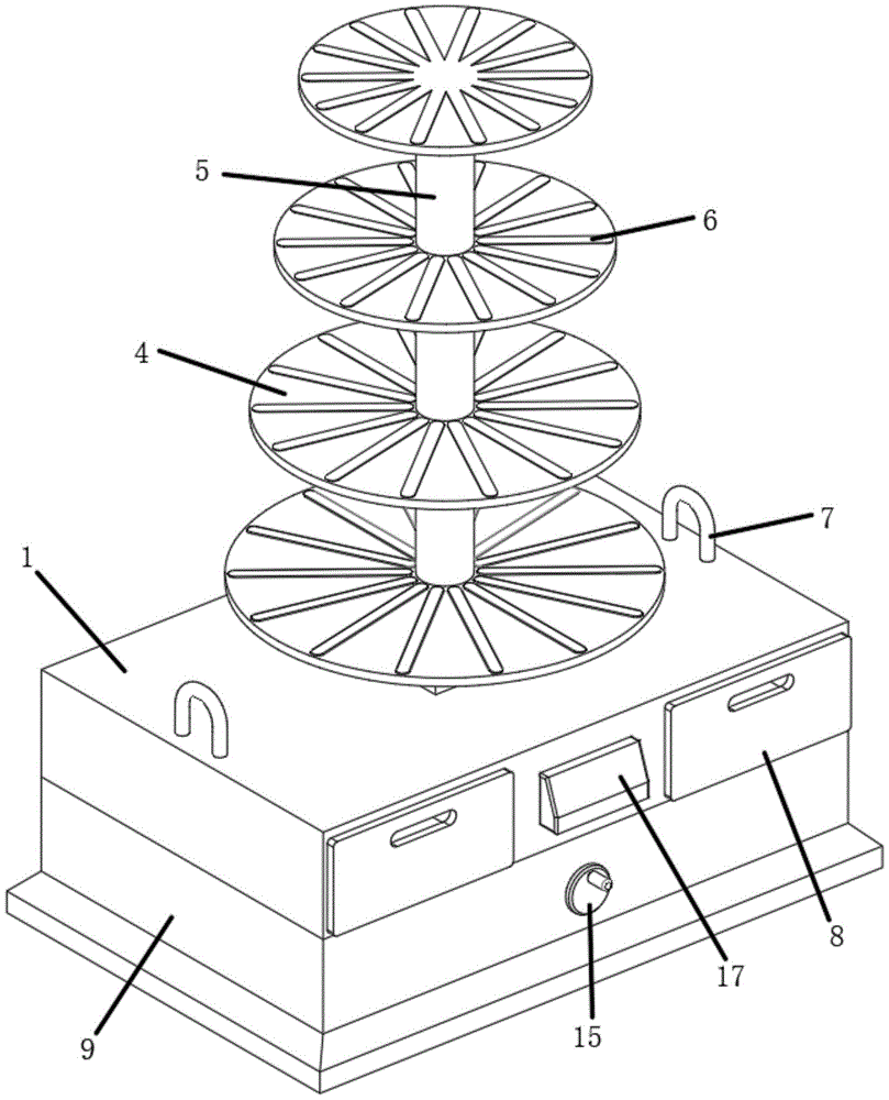
FIG. 1 is a front view of an industrial design display stand in accordance with the present invention;
FIG. 2 is a cross-sectional view of an industrial design display stand in accordance with the present invention;
FIG. 3 is an exploded view of a lift adjustment assembly for an industrial design display stand in accordance with the present invention;
fig. 4 is a front view of an internal structure of a mounting base of a display stand for industrial design according to the present invention.
In the figure: the device comprises an installation table 1, a support seat 2, an angle adjusting assembly 3, a placing table 4, a lifting adjusting assembly 5, a non-slip strip 6, a pull ring 7, an storage drawer 8, an installation base 9, a guide column 10, a lifting plate 11, a fixing block 12, a connecting plate 13, a moving block 14, a driving assembly 15, a universal wheel 16, a controller 17, a motor 301, a first worm 302, a first worm gear 303, a first 304 support column, a support sleeve 501, a 502 limit groove, a threaded lead screw 503, a limit block 504, an internal thread adjusting sleeve 505, a transmission column 1501, a second worm gear 1502, a second worm gear 1503, a double-threaded lead screw 1504, an adjusting disc 1505 and a rocker 1506.
Detailed Description
The technical solutions in the embodiments of the present invention will be clearly and completely described below with reference to the drawings in the embodiments of the present invention, and it is obvious that the described embodiments are only a part of the embodiments of the present invention, and not all of the embodiments. All other embodiments, which can be derived by a person skilled in the art from the embodiments given herein without making any creative effort, shall fall within the protection scope of the present invention.
Referring to fig. 1-4, a display stand for industrial design comprises an installation stand 1, a support base 2 is arranged in the middle of the upper surface of the installation stand 1, an angle adjusting component 3 for generating angular displacement is fixedly arranged between the support base 2 and the installation stand 1, a plurality of placing stands 4 are fixedly arranged on the upper surface of the support base 2, a plurality of lifting adjusting components 5 are fixedly arranged between the plurality of placing stands 4, each lifting adjusting component 5 comprises a support sleeve 501, the support sleeve 501 is fixedly connected with the upper surface of the placing stand 4, a plurality of limiting grooves 502 are equiangularly arranged on the inner wall of the support sleeve 501, a threaded lead screw 503 is sleeved on the inner wall of the support sleeve 501, a plurality of limiting blocks 504 corresponding to the limiting grooves 502 are equiangularly fixedly arranged on one side of the surface of the threaded lead screw 503, one end of the threaded lead screw 503 is fixedly connected with the lower surface of the placing stand 4, an internal thread adjusting sleeve 505 is rotatably connected with the top of the support sleeve 501, the inner wall of the internal thread adjusting sleeve 505 is in threaded connection with the threaded lead screw 503, the mounting base 9 is fixedly arranged on the lower surface of the mounting table 1, guide posts 10 are fixedly arranged on two sides of the inner wall of the mounting base 9, a lifting plate 11 is slidably connected with the two guide posts 10, two fixed blocks 12 are fixedly arranged on two sides of the upper surface of the lifting plate 11, the fixed blocks 12 are rotatably connected with connecting plates 13, one sides, far away from the fixed blocks 12, of the connecting plates 13 are rotatably connected with moving blocks 14, the moving blocks 14 are slidably connected with the top of the inner wall of the mounting base 9, the mounting base 9 is fixedly provided with a driving assembly 15 enabling the moving blocks 14 to generate displacement, four universal wheels 16 are fixedly arranged on the lower surface of the lifting plate 11, and four through holes corresponding to the universal wheels 16 are formed in the lower surface of the mounting base 9.
Specifically, angle adjusting component 3 includes motor 301, the bottom fixed connection of motor 301 and mount table 1 inner wall, and the output shaft of motor 301 is fixed and is equipped with a worm 302, and one side toothing of a worm 302 is equipped with a worm wheel 303, and a worm wheel 303 is fixed and is equipped with support column 304, and the one end of support column 304 is rotated with the bottom of mount table 1 inner wall and is connected, and the one end that worm wheel 303 was kept away from to support column 304 runs through mount table 1 and with supporting seat 2 fixed connection.
Specifically, drive assembly 15 includes drive column 1501, drive column 1501 is connected with the inner wall rotation of installation base 9, two worms 1502 are all fixed to the both sides on drive column 1501 surface, two sides of worm 1502 all connect the toothing and are equipped with two worm wheels 1503, two worm wheels 1503 all fix and are equipped with two screw thread 1504, and the both ends of two screw thread 1504 all rotate with the inner wall of installation base 9 and be connected, two screw thread 1504 respectively with the movable block 14 threaded connection, the one end of drive column 1501 runs through installation base 9 and the fixed regulating disc 1505 that is equipped with, one side rotation of regulating disc 1505 is connected and is equipped with rocking arm 1506.
Specifically, pull rings 7 are fixedly arranged on two sides of the upper surface of the mounting platform 1, and two storage drawers 8 are inserted into one side of the mounting platform 1.
Specifically, the placing table 4 is arranged from large to small from the bottom to the upper diameter, and a plurality of anti-slip strips 6 are fixedly arranged on the upper surface of the placing table 4.
Specifically, a controller 17 is fixedly arranged on one side of the mounting table 1.
The use principle and the use flow of the utility model are as follows: the worker uses the pull rod to pull the pull ring 7 to move the utility model to a proper position, then shakes the rocker arm 1506 to enable the adjusting disc 1505 to drive the transmission column 1501 to start rotating, enables the double-thread screw rod 1504 to start rotating under the transmission of the worm gear 1502 and the worm wheel 1503, enables the lifting plate 11 to drive the universal wheel 16 to start moving up under the guide of the guide column 10 under the matching of the threads until the lower surface of the installation base 9 is attached to the ground, completes the fixation of the utility model, then pulls out the storage drawer 8 to place the exhibit therein on the upper surface of the placing table 4, simultaneously rotates the internal thread adjusting sleeve 505 according to the size of the exhibit, enables the thread screw rod 503 to start moving under the matching of the threads until the distance between two adjacent placing tables 4 is adjusted to a proper height, and then uses the controller 17 to control the motor 301 to start working under the transmission of the worm gear 302 and the worm wheel 303 to enable the supporting column 304 to drive the supporting seat 2, The placing table 4 and the lifting adjusting component 5 start to rotate, and the exhibit starts to rotate along with the rotation, so that people can enjoy the exhibit.
Finally, it should be noted that: although the present invention has been described in detail with reference to the foregoing embodiments, it will be apparent to those skilled in the art that changes may be made in the embodiments and/or equivalents thereof without departing from the spirit and scope of the utility model. Any modification, equivalent replacement, or improvement made within the spirit and principle of the present invention should be included in the protection scope of the present invention.