CN215931539U - Pipeline pressure test tool capable of being installed in limited space - Google Patents

Pipeline pressure test tool capable of being installed in limited space Download PDF

Info

Publication number
CN215931539U
CN215931539U CN202122281146.6U CN202122281146U CN215931539U CN 215931539 U CN215931539 U CN 215931539U CN 202122281146 U CN202122281146 U CN 202122281146U CN 215931539 U CN215931539 U CN 215931539U
Authority
CN
China
Prior art keywords
main body
pressure testing
pipeline
limited space
interface
Prior art date
Legal status (The legal status is an assumption and is not a legal conclusion. Google has not performed a legal analysis and makes no representation as to the accuracy of the status listed.)
Active
Application number
CN202122281146.6U
Other languages
Chinese (zh)
Inventor
柳伟
刘楠
张春瑞
潘峰
李健
吕先起
刘山山
宋超乐
Current Assignee (The listed assignees may be inaccurate. Google has not performed a legal analysis and makes no representation or warranty as to the accuracy of the list.)
Offshore Engineering (Zhuhai) Heavy Industry Co., Ltd.
Original Assignee
COOEC Fluor Heavy Industries Co Ltd
Priority date (The priority date is an assumption and is not a legal conclusion. Google has not performed a legal analysis and makes no representation as to the accuracy of the date listed.)
Filing date
Publication date
Application filed by COOEC Fluor Heavy Industries Co Ltd filed Critical COOEC Fluor Heavy Industries Co Ltd
Priority to CN202122281146.6U priority Critical patent/CN215931539U/en
Application granted granted Critical
Publication of CN215931539U publication Critical patent/CN215931539U/en
Active legal-status Critical Current
Anticipated expiration legal-status Critical

Links

Images

Landscapes

  • Examining Or Testing Airtightness (AREA)

Abstract

本实用新型涉及管道安装检验技术领域,具体涉及一种可在有限空间内安装的管道试压工装,本实用新型的管道试压工装包括主体、分设在主体两端的密封组件和设置在主体一侧的接口,两根管道连接时能够压紧主体,通过密封组件确保主体与管道之间的密封性,并且接口自主体的一侧引出以连通外部试压设备;该管道试压工装可以代替原有的法兰,在有限的空间内也可以自一侧置入两根管道之间的连接处,安装该管道试压工装时管道无需移位,操作方便,提升作业效率,降低人力成本。
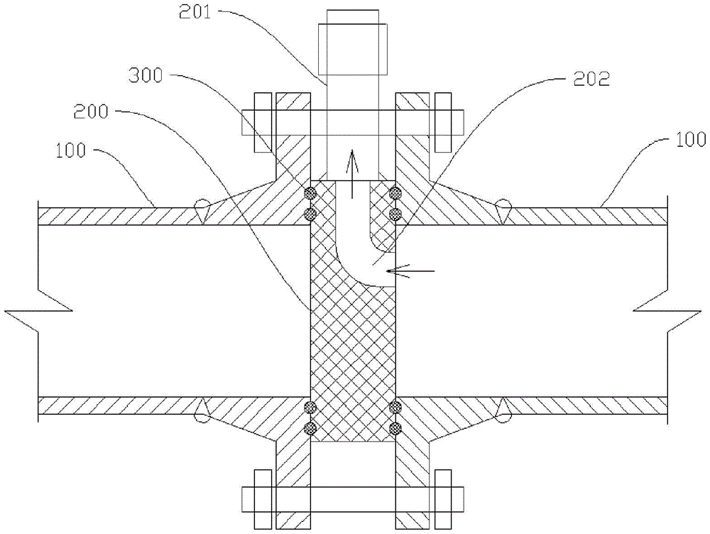
Figure 202122281146

The utility model relates to the technical field of pipeline installation and inspection, in particular to a pipeline pressure test tool that can be installed in a limited space. The pipeline pressure test tool of the utility model comprises a main body, sealing components arranged at both ends of the main body and a sealing assembly arranged on one side of the main body. When the two pipes are connected, the main body can be pressed, the sealing between the main body and the pipeline is ensured, and the interface is drawn from one side of the main body to connect with external pressure testing equipment; the pipeline pressure testing tool can replace the original The flange can also be placed in the connection between two pipes from one side in a limited space. When installing the pipe pressure test tool, the pipe does not need to be displaced, which is easy to operate, improves work efficiency and reduces labor costs.

Figure 202122281146

Description

Pipeline pressure test tool capable of being installed in limited space
Technical Field
The utility model relates to the technical field of pipeline installation and inspection, in particular to a pipeline pressure test tool capable of being installed in a limited space.
Background
In the petrochemical module construction, after the pipeline construction operation is finished, a pressure test needs to be carried out on the system, and a pressure test tool cannot be installed due to limited space of some equipment ports. The traditional method is to shift and install the pipeline after cutting the pipeline, the guide, the support and even the welded junction, and then carry out secondary welding operation after completing the pressure test, so that the method has the problems of reducing the working efficiency and consuming the labor cost.
SUMMERY OF THE UTILITY MODEL
The technical scheme adopted by the utility model for solving the technical problems is as follows: the utility model provides a pipeline pressure testing frock that can install in finite space installs the junction between two pipelines, includes the main part, the both ends of main part are provided with seal assembly respectively, one side of main part is provided with the interface of intercommunication outside pressure testing equipment.
Further, the main body is plate-shaped, and a pressure test passage communicated with the interface is arranged on the main body.
Further, the inlet end of the pressure test passage is arranged on the end face of the main body, the outlet end of the pressure test passage is arranged on the side face of the main body and communicated with the interface, and the inlet end is connected with the outlet end in an arc shape.
Further, the main body is annular, and the inner diameter of the annular main body is equal to the inner diameter of the pipeline.
Furthermore, one end of the interface is welded and fixed on the main body, and the other end of the interface is provided with a connecting external thread.
Further, the sealing assembly comprises at least two sealing rings, and the diameters of the cross sections of the at least two sealing rings are different.
Further, the outer diameter of the interface is smaller than the thickness of the main body.
The utility model has the following beneficial effects: the pipeline pressure test tool comprises a main body, sealing assemblies and a connector, wherein the sealing assemblies are respectively arranged at two ends of the main body, the connector is arranged at one side of the main body, the main body can be compressed when the two pipelines are connected, the sealing performance between the main body and the pipelines is ensured through the sealing assemblies, and the connector is led out from one side of the main body to be communicated with external pressure test equipment; the pipeline pressure testing tool can replace an original flange, a joint between two pipelines can be arranged from one side in a limited space, the pipeline does not need to be shifted when the pipeline pressure testing tool is installed, operation is convenient, operation efficiency is improved, and labor cost is reduced.
Drawings
The above and/or additional aspects and advantages of the present invention will become apparent and readily appreciated from the following description of the embodiments, taken in conjunction with the accompanying drawings of which:
FIG. 1 is a schematic cross-sectional view of one embodiment of the present invention;
fig. 2 is a schematic cross-sectional view of another embodiment of the present invention.
Detailed Description
In order to make the objects, technical solutions and advantages of the present invention more apparent, the present invention is described in further detail below with reference to the accompanying drawings and embodiments. It should be understood that the specific embodiments described herein are merely illustrative of the utility model and are not intended to limit the utility model.
Referring to fig. 1, the pipeline pressure testing tool which can be installed in a limited space is installed at a connection position between two pipelines 100 and comprises a main body 200, two ends of the main body 200 are respectively provided with a sealing assembly 300, one side of the main body 200 is provided with an interface 201, the interface 201 is used for being communicated with external pressure testing equipment, specifically, the main body 200 is plate-shaped, a pressure testing passage 202 communicated with the interface 201 is arranged on the main body 200, at the moment, the plate-shaped main body 200 can seal the pipelines 100, the pipelines 100 are only communicated with the pressure testing passage 202, an inlet end of the pressure testing passage 202 is arranged on an end face of the plate-shaped main body 200, an outlet end is arranged on a side face of the main body 200 and is communicated with the interface 201, and the inlet end and the outlet end are connected in an arc shape, so that the main body 200 is eroded due to large impact of fluid; in some tests such as static pressure tests, the on-off of the pipelines 100 needs to be cut off, and at the same time, the plate-shaped main body 200 can be used for cutting off and can be communicated with external pressure test equipment through the interface 201 for testing.
Referring to fig. 2, in another embodiment of the pipeline pressure testing tool, a main body 200 of the pipeline pressure testing tool is annular, and the inner diameter of the annular main body 200 is equal to the inner diameter of the pipeline 100, at this time, the two pipelines 100 are communicated, and the pipeline pressure testing tool of this structure is suitable for being used in dynamic pressure testing, specifically, a port 201 is led out from one side of the main body 200 and is communicated with external pressure testing equipment, at this time, the pipeline pressure testing tool does not block fluid flowing in the pipeline 100, so that dynamic pressure in the pipeline 100 at the test position can be tested.
In some embodiments, one end of the interface 201 is welded and fixed on the main body 200, specifically, a drill hole is provided at one side of the main body 200, the interface 201 is communicated with the inside of the main body 200 through the drill hole, a connection external thread is provided at the other end of the interface 201, the interface 201 can be tightly installed with an external pressure test device through a threaded connection, and of course, a quick installation joint suitable for the pipeline 100 can be further provided at the interface 201.
In some embodiments, referring to fig. 1 and 2, the sealing assembly 300 includes at least two sealing rings, the diameters of the end faces of the at least two sealing rings are different, and at least two sealing structures are formed between the pipe 100 and the main body 200 by the at least two sealing rings, so as to avoid the problem of inaccurate test caused by leakage between the pipe 100 and the main body 200; in other embodiments, a sealing ring may be used, as long as a good seal is ensured between the pipe 100 and the main body 200; of course, the diameters of the at least two sealing rings are equal, the main body 200 is pressed simultaneously when the two pipes 100 are fastened by bolts, and then the sealing rings are pressed by the main body 200 and the pipes 100 to realize sealing connection; in other embodiments, an annular groove for accommodating a sealing ring is further disposed on the end surface of the main body 200, the sealing ring is mounted in the annular groove, and when the main body 200 is inserted into the region between the two pipes 100 from one side, the problem that the sealing ring is displaced or even falls off due to friction between the sealing ring and the end surface of the pipe 100 can be avoided.
In some embodiments, the outer diameter of the interface 201 is smaller than the thickness of the main body 200, and when the pipeline pressure testing tool is installed, the original flange is removed, and then the pipeline pressure testing tool is placed at the joint between two pipelines 100 from one side, so that the two pipelines 100 can be stably pressed against the main body 200 without interfering with the interface 201.
It should be noted that, the pipeline pressure testing tools of all the above embodiments can be plugged into or placed in the joint between the two pipelines 100 from one side, and the two pipelines 100 are connected and pressed on the main body 200 by bolts, so that sealing is realized, operation is convenient, efficiency is improved, and the pipeline 100 can be led out of the interface 201 to be connected with external pressure testing equipment without displacement.
While the foregoing is directed to the preferred embodiment of the present invention, it will be understood by those skilled in the art that various changes and modifications may be made without departing from the spirit and scope of the utility model.

Claims (7)

1. The utility model provides a pipeline pressure testing frock that can install in finite space, installs the junction between two pipelines (100), its characterized in that, includes main part (200), the both ends of main part (200) are provided with seal assembly (300) respectively, one side of main part (200) is provided with interface (201) that communicate outside pressure testing equipment.
2. The pipeline pressure testing tool capable of being installed in a limited space according to claim 1, wherein the main body (200) is plate-shaped, and a pressure testing passage (202) communicated with the interface (201) is arranged on the main body (200).
3. The pipeline pressure testing tool capable of being installed in a limited space according to claim 2, wherein an inlet end of the pressure testing passage (202) is arranged on an end face of the main body (200), an outlet end is arranged on a side face of the main body (200) and is communicated with the interface (201), and the inlet end and the outlet end are connected in an arc shape.
4. The tool for testing pressure of pipelines capable of being installed in a limited space according to claim 1, wherein the main body (200) is annular, and the inner diameter of the annular main body (200) is equal to the inner diameter of the pipeline (100).
5. The pipeline pressure testing tool capable of being installed in a limited space according to claim 1, wherein one end of the interface (201) is welded and fixed on the main body (200), and the other end is provided with a connecting external thread.
6. The pipeline pressure testing tool capable of being installed in a limited space according to claim 1, wherein the sealing assembly (300) comprises at least two sealing rings, and the diameters of the cross sections of the at least two sealing rings are different.
7. The pipeline pressure testing tool capable of being installed in a limited space as claimed in claim 1, wherein the outer diameter dimension of the interface (201) is smaller than the thickness dimension of the main body (200).
CN202122281146.6U 2021-09-18 2021-09-18 Pipeline pressure test tool capable of being installed in limited space Active CN215931539U (en)

Priority Applications (1)

Application Number Priority Date Filing Date Title
CN202122281146.6U CN215931539U (en) 2021-09-18 2021-09-18 Pipeline pressure test tool capable of being installed in limited space

Applications Claiming Priority (1)

Application Number Priority Date Filing Date Title
CN202122281146.6U CN215931539U (en) 2021-09-18 2021-09-18 Pipeline pressure test tool capable of being installed in limited space

Publications (1)

Publication Number Publication Date
CN215931539U true CN215931539U (en) 2022-03-01

Family

ID=80417445

Family Applications (1)

Application Number Title Priority Date Filing Date
CN202122281146.6U Active CN215931539U (en) 2021-09-18 2021-09-18 Pipeline pressure test tool capable of being installed in limited space

Country Status (1)

Country Link
CN (1) CN215931539U (en)

Similar Documents

Publication Publication Date Title
JP2021139491A (en) Connector for piping, and connection device for piping including the same
CN112728248A (en) Insulating sealing gasket with leakage test function
CN103851288A (en) General clamping jaw type connector
CN213040019U (en) Pipeline connecting and sealing device for conveying fluid
CN112483648B (en) Probe sealing structure for high-pressure fluid pipeline
CN210830873U (en) water pipe adapter
CN219624817U (en) Clamping tool for welding type valve flow test
CN111457176A (en) Pipeline connecting and sealing device for conveying fluid
CN209539429U (en) Two-tube vehicle exhaust switching tooling
CN207650008U (en) Tubing clamps adapter fixture temporarily
CN214500355U (en) Pressure pipeline connecting and sealing device for conveying fluid
CN223235544U (en) An assembly sealing tool for a water body measuring device
CN111272361B (en) Single tube pressure test and leakage detection tool for tube type heat exchanger
CN116358788A (en) A method that can simultaneously test the airtightness of multiple independent chambers
CN205118510U (en) Flange convenient to fluid flow in detecting tube
CN214119286U (en) Pipeline connecting structure
CN221922364U (en) A compression pipe pipeline structure
CN222297291U (en) Sensor connects mouth and pipeline subassembly
CN223938931U (en) Pipeline butt joint detection equipment for water conservancy and hydropower construction
CN214093485U (en) Pipe fittings for testing the air tightness of pipes
CN224176036U (en) Detection tool and detection system for air tightness of radiator core
CN111912581A (en) Single-group flange tightness test method
CN219064901U (en) Aircraft ACM performance test equipment
CN119223027B (en) Exhaust pipes capable of on-site air tightness/air pressure testing and test methods
CN221323658U (en) Vibration-proof structure of metal hose

Legal Events

Date Code Title Description
GR01 Patent grant
GR01 Patent grant
CP03 Change of name, title or address

Address after: 519000 Guangdong Province, Zhuhai City, Jinwan District, Gao Lan Port Economic Zone, Pinggang Road No. 99

Patentee after: Offshore Engineering (Zhuhai) Heavy Industry Co., Ltd.

Country or region after: China

Address before: 519000 Guangdong Province, Zhuhai City, Jinwan District, Gao Lan Port Economic Zone, Pinggang Road No. 99

Patentee before: COOEC-FLUOR HEAVY INDUSTRIES Co.,Ltd.

Country or region before: China