CN215919411U - A laser cutting waste collection device - Google Patents
A laser cutting waste collection device Download PDFInfo
- Publication number
- CN215919411U CN215919411U CN202122149899.1U CN202122149899U CN215919411U CN 215919411 U CN215919411 U CN 215919411U CN 202122149899 U CN202122149899 U CN 202122149899U CN 215919411 U CN215919411 U CN 215919411U
- Authority
- CN
- China
- Prior art keywords
- pipe
- water
- assembly
- collecting
- workbench body
- Prior art date
- Legal status (The legal status is an assumption and is not a legal conclusion. Google has not performed a legal analysis and makes no representation as to the accuracy of the status listed.)
- Expired - Fee Related
Links
Images

Landscapes
- Laser Beam Processing (AREA)
Abstract
The utility model discloses a laser cutting waste collection device which comprises a workbench body in a box-shaped structure, wherein a placement component for placing plates is arranged at the top end of the workbench body, a cooling component for cooling high-temperature slag and a collection component for collecting slag and waste are arranged inside the workbench body, the collection component is arranged below the cooling component, a water collection cavity is arranged below the collection component, a water outlet communicated with the water collection cavity is arranged at one side of the workbench body, an exhaust component communicated with an inner cavity of the workbench body is arranged on one side plate of the workbench body, an air inlet of the exhaust component is positioned below the placement component, and an air outlet of the exhaust component is connected with an exhaust pipe. Above-mentioned technical scheme prevents the high-temperature slag adhesion on the filter screen through setting up the cooling module and cools off the high-temperature slag, the clearance of being convenient for to set up and collect the subassembly and be convenient for collect slag and waste material, reduce clearance and collect the artifical intensity of labour of waste material in-process.
Description
Technical Field
The utility model relates to an auxiliary device of laser cutting equipment for performing pattern cutting on an aluminum plate, in particular to a laser cutting waste collecting device.
Background
In the process of arranging the decoration and the electronic equipment of the gas station, in order to improve the beautification of the gas station, the laser cutting can be facilitated to cut patterns on the aluminum plate so as to decorate the gas station, and not only can slag be generated in the cutting process, but also small-sized waste materials separated by cutting can be generated.
The process discovery that uses laser cutting to carve flowers to aluminum plate, current cutting workstation structure is fixed with in grid plate below and connects the flitch to prevent that the waste material from directly falling on the workshop bottom surface. However, the high-temperature slag is adhered to the material receiving plate and is difficult to peel off, so that the cleaning is inconvenient, and the more the slag is, the subsequent use is influenced. And the waste materials (small-sized waste materials generated in the process of cutting patterns) leaked from the grating plate fall on the material receiving plate, so that the waste materials are not easy to clean, the cleaning workload is extremely large, and the waste materials are not easy to recycle.
SUMMERY OF THE UTILITY MODEL
To the defects and shortcomings of the prior art, the laser cutting waste collecting device is provided.
In order to achieve the purpose, the utility model provides the following technical scheme:
a laser cutting waste collecting device comprises a workbench body in a box-shaped structure, a placing component for placing a plate is arranged at the top end of the workbench body, a cooling component for cooling the high-temperature slag and a collecting component for collecting the slag and the waste are arranged in the workbench body, the collecting component is arranged below the cooling component and comprises a collecting frame which is arranged in the workbench body in a sliding way, a filter screen is fixed at the bottom of the inner wall of the collecting frame, a water collecting cavity is arranged below the collecting component, a water outlet communicated with the water collecting cavity is arranged at one side of the workbench body, an exhaust assembly communicated with the inner cavity of the workbench body is arranged on one side plate of the workbench body, an air inlet of the exhaust assembly is located below the placement assembly, and an air outlet of the exhaust assembly is connected with an exhaust pipe.
Preferably, the placing assembly comprises a placing frame fixed on an opening at the top end of the workbench body, the placing frame is of a frame structure, and a grid plate is arranged on the placing frame.
Preferably, the cooling assembly comprises a water spray pipe and a plurality of spray heads arranged on the water spray pipe, the water spray pipe is arranged on the bottom surface of the grid plate through an installation block, the spray heads are rotary spray heads, the water spray pipe is connected with a water supply pipe, and the water supply pipe penetrates out of the workbench body and is connected with a water source.
Preferably, a water pump is arranged in the water collecting cavity.
Preferably, a handle is arranged on the collecting frame, at least two groups of rollers are arranged on two sides of the bottom of the collecting frame respectively, the rollers are located in the slide ways in a matched mode, the slide ways are arranged on the corresponding slide rails, and the slide rails are fixed on the side plates of the workbench body.
As another technical scheme of the utility model, the cooling assembly comprises a water spray pipe and a plurality of spray heads arranged on the water spray pipe, the water spray pipe is arranged on the bottom surface of the grid plate through an installation block and a connecting pipe, and the top end of the connecting pipe is rotatably connected with the installation block.
Above-mentioned technical scheme still including being used for the drive spray pipe pivoted drive assembly, drive assembly includes dwang and driving motor, dwang one end is passed a curb plate of workstation body and stretch into its inner chamber, this dwang is located initiative bevel gear is installed to the one end of workstation body inner chamber, this initiative bevel gear with install driven bevel gear meshing on the connecting pipe, the dwang is located the one end in the workstation body outside with the driving motor output shaft passes through coupling joint.
Preferably, the mounting block is of an internal hollow structure, the bottom of the mounting block is provided with a vertical pipe communicated with an inner cavity of the mounting block, the mounting block is connected with a water supply pipe, the bottom end of the vertical pipe is connected with the top end of the connecting pipe through a bearing, and a sealing ring is arranged between the vertical pipe at the bottom of the bearing and the connecting pipe.
In conclusion, the utility model has the following beneficial effects:
1. according to the utility model, the cooling assembly is arranged to cool the high-temperature slag, so that the high-temperature slag is prevented from being adhered to the filter screen, the cleaning is convenient, the cleaning difficulty is reduced, the collection assembly is arranged to collect the slag and the waste materials conveniently, the labor intensity of workers in the process of cleaning and collecting the waste materials is reduced, and the collection of the waste materials generated in the cutting process is facilitated, so that the waste materials are recycled, and the processing cost of enterprises is reduced;
2. the pull-type collecting frame is arranged, so that slag and waste materials in the collecting frame can be conveniently cleaned, and the use is convenient.
Drawings
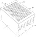
FIG. 1 is a schematic perspective view of the structure of example 1;
FIG. 2 is an internal structural view of embodiment 1;
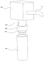
fig. 3 is a schematic view showing the connection relationship of the mounting blocks and the connections of the cooling module of embodiment 2.
Description of reference numerals: 1. a table body; 2. placing the component; 201. placing a rack; 202. a grid plate; 3. a cooling assembly; 301. a water spray pipe; 302. a spray head; 303. mounting blocks; 304. a connecting pipe; 305. a standpipe 306, bearings; 307. mounting grooves; 5. a water collection cavity; 6. an exhaust assembly; 7. a handle; 8. a drive assembly; 801. rotating the rod; 802. a drive bevel gear; 803. a driven bevel gear; 9. a water supply pipe.
Detailed Description
The utility model is described in further detail below with reference to the accompanying figures 1-3:
example 1: referring to fig. 1 and 2, a laser cutting waste collecting device comprises a workbench body 1 in a box-shaped structure, a placing component 2 for placing plates is arranged at the top end of the workbench body 1, a cooling component 3 for cooling high-temperature slag and a collecting component 4 for collecting slag and waste are arranged inside the workbench body 1, the collecting component 4 is arranged below the cooling component 3, the collecting component 4 comprises a collecting frame 401 arranged inside the workbench body 1 in a sliding manner, a filter screen 402 is fixed at the bottom of the inner wall of the collecting frame 401, a water collecting cavity 5 is arranged below the collecting component, a water outlet (not shown in the figure) communicated with the water collecting cavity 5 is arranged at one side of the workbench body 1, an exhaust component communicated with the inner cavity of the workbench body 1 is arranged on one side plate of the workbench body 1, and an air inlet of the exhaust component 6 is positioned below the placing component 2, the air outlet of the air conditioner is connected with an exhaust pipe. Exhaust assembly 6 is air discharge fan or air exhauster, sets up its air inlet in the below of placing subassembly 2, not only can suck away other dissolved air that produce when cutting flowers, prevents to suck the human body, can also prevent to take away cooling module spun water.
Preferably, the placing assembly 2 comprises a placing frame 201 fixed on the top opening of the workbench body 1, the placing frame 201 is of a frame-shaped structure, and a grid plate 202 is arranged on the placing frame 201.
The cooling assembly 3 comprises a water spray pipe 301 and a plurality of spray heads 302 arranged on the water spray pipe 301, the water spray pipe 301 is arranged on the bottom surface of the grating plate 202 through an installation block 303, the spray heads 301 are rotary spray heads and are convenient for spraying water in all directions in the workbench body 1, and the water spray pipe 303 is a cross rod or a cross shape. The spray pipe 301 is connected with a water supply pipe, and the water supply pipe penetrates out of the workbench body 1 to be connected with a water source, so that the water source is provided for the spray pipe 301.
A water pump (not shown) is arranged in the water collecting cavity 5, and the water pump can be used as a circulating water pump, is connected with the water spraying pipe 301 through a water return pipe, and closes a valve on a water supply pipe when circulating water is adopted. The circulating pipeline is designed in such a way that water resources can be saved. Of course, the water pump may be used as a drain pump, and the water pump may be connected to the drain port through a drain pipe to drain the water in the water collecting chamber.
Preferably, the handle 7 is arranged on the collecting frame 401, at least two groups of rollers are arranged on two sides of the bottom of the collecting frame 401 respectively, the rollers are adaptively positioned in the slide ways, the rollers can roll in the slide ways, the drawing stability of the collecting frame 401 is improved, the two slide ways are arranged on the corresponding slide rails, and the slide rails are fixed on the side plates of the workbench body. The drawing collection frame of being convenient for of so design to be convenient for clear up and go out to fall into slag and the waste material of collecting in the frame, intensity of labour when reducing the clearance improves cleaning efficiency, also is convenient for simultaneously the recycle to the waste material.
Example 2: referring to fig. 1, 2 and 3, the structure of the present embodiment 2 is substantially the same as that of the present embodiment except that: the cooling assembly 3 comprises a water spraying pipe 301 and a plurality of nozzles 302 arranged on the water spraying pipe 301, the water spraying pipe is arranged on the bottom surface of the grating plate 202 through a mounting block 303 and a connecting pipe 304, and the top end of the connecting pipe 304 is rotatably connected with the mounting block 303.
The embodiment further comprises a driving assembly 8 for driving the water spraying pipe 301 to rotate, the driving assembly comprises a rotating rod 801 and a driving motor (not shown in the figure), one end of the rotating rod 801 penetrates through one side plate of the workbench body 1 and extends into an inner cavity of the workbench body 1, a driving bevel gear 402 is installed at one end, located in the inner cavity of the workbench body, of the rotating rod 801, the driving bevel gear 402 is meshed with a driven bevel gear 803 installed on the connecting pipe 304, and one end, located outside the workbench body, of the rotating rod 801 is connected with an output shaft of the driving motor through a coupler.
The mounting block 303 is hollow inside and has a vertical pipe 305 at the bottom communicating with the inner cavity thereof, and the mounting block 303 is connected to the water supply pipe 9 to supply water through the water supply pipe 9. The standpipe 305 bottom is connected through bearing 306 with the connecting pipe top, has seted up the bearing frame on the connecting pipe is inside to be provided with the sealing washer between standpipe 305 and the connecting pipe 304 of bearing 306 bottom, the sealing washer is installed and is being seted up in the mounting groove 306 of standpipe 305 bottom, prevents through the sealing washer that water from getting into the bearing room, and then damages bearing 9, also prevents that bearing lubricating oil from getting into in the connecting pipe 304.
When the laser cutting workbench disclosed by the utility model is used for cutting patterns of an aluminum plate, high-temperature molten slag is cooled by the cooling assembly 3 and then falls into the collecting assembly 4, and the waste and the molten slag are collected, so that the laser cutting workbench is convenient to clean and is beneficial to recycling the waste.
The present embodiment is only for explaining the present invention, and it is not limited to the present invention, and those skilled in the art can make modifications of the present embodiment without inventive contribution as needed after reading the present specification, but all of them are protected by patent law within the scope of the claims of the present invention.
Claims (8)
Priority Applications (1)
| Application Number | Priority Date | Filing Date | Title |
|---|---|---|---|
| CN202122149899.1U CN215919411U (en) | 2021-09-07 | 2021-09-07 | A laser cutting waste collection device |
Applications Claiming Priority (1)
| Application Number | Priority Date | Filing Date | Title |
|---|---|---|---|
| CN202122149899.1U CN215919411U (en) | 2021-09-07 | 2021-09-07 | A laser cutting waste collection device |
Publications (1)
| Publication Number | Publication Date |
|---|---|
| CN215919411U true CN215919411U (en) | 2022-03-01 |
Family
ID=80419098
Family Applications (1)
| Application Number | Title | Priority Date | Filing Date |
|---|---|---|---|
| CN202122149899.1U Expired - Fee Related CN215919411U (en) | 2021-09-07 | 2021-09-07 | A laser cutting waste collection device |
Country Status (1)
| Country | Link |
|---|---|
| CN (1) | CN215919411U (en) |
Cited By (2)
| Publication number | Priority date | Publication date | Assignee | Title |
|---|---|---|---|---|
| CN115121969A (en) * | 2022-08-31 | 2022-09-30 | 江苏民生重工有限公司 | Laser cutting device for shell of desulfurizing tower |
| CN116393799A (en) * | 2023-06-05 | 2023-07-07 | 山东海纳等离子科技有限公司 | Cutting equipment for plasma cladding workpiece |
-
2021
- 2021-09-07 CN CN202122149899.1U patent/CN215919411U/en not_active Expired - Fee Related
Cited By (3)
| Publication number | Priority date | Publication date | Assignee | Title |
|---|---|---|---|---|
| CN115121969A (en) * | 2022-08-31 | 2022-09-30 | 江苏民生重工有限公司 | Laser cutting device for shell of desulfurizing tower |
| CN116393799A (en) * | 2023-06-05 | 2023-07-07 | 山东海纳等离子科技有限公司 | Cutting equipment for plasma cladding workpiece |
| CN116393799B (en) * | 2023-06-05 | 2023-09-01 | 山东海纳等离子科技有限公司 | Cutting equipment for plasma cladding workpiece |
Similar Documents
| Publication | Publication Date | Title |
|---|---|---|
| CN209773645U (en) | Gear hobbing machine cooling and cleaning device | |
| CN211989841U (en) | Cleaning and dust removing device for aluminum alloy door and window production | |
| CN214978494U (en) | Laser cutting machine waste material concentrates collection device | |
| CN223755838U (en) | A waste heat recovery device for heat supply | |
| CN119347520B (en) | Automatic discharge system of high-efficient waste material of vacuum pump machine tool | |
| CN114839190A (en) | Flotation foam monitoring device with automatic cleaning function and use method thereof | |
| CN222221742U (en) | A precision machinery manufacturing processing and cleaning device | |
| CN108544331A (en) | A kind of burnishing device of five metalworkings | |
| CN119952116A (en) | A vertical milling machine for machining hydraulic pump housing parts with automatic material removal | |
| CN210817215U (en) | Cooling device for ring rolling forging | |
| CN221604366U (en) | Adjustable processing clamp of air conditioner external unit | |
| CN112571060A (en) | All-round intelligent welding machine of slice standard festival main limb | |
| CN216502553U (en) | Engine cylinder block mills a device | |
| CN218395990U (en) | A punching device for driving shafts of automobiles | |
| CN216731267U (en) | A high-efficient dust collecting equipment for sheet metal processing | |
| CN215490584U (en) | A kind of aluminum processing cooling equipment | |
| CN213970192U (en) | Machine tool for producing 5G metal parts | |
| CN222971019U (en) | Perforating device for valve body machining | |
| CN223630172U (en) | An internal support fixture for machining motor housing | |
| CN113927075A (en) | Engine cylinder block mills a device | |
| CN215617431U (en) | Dust device is used in bearing processing | |
| CN220481052U (en) | Milling machine sweeps cleaning device | |
| CN220240880U (en) | Machine tool cooling system with adjustable flow | |
| CN221604816U (en) | Dustproof cutting equipment of stone material processing | |
| CN213319106U (en) | Cutting head elevation structure of milling machine for steel plate processing |
Legal Events
| Date | Code | Title | Description |
|---|---|---|---|
| GR01 | Patent grant | ||
| GR01 | Patent grant | ||
| CF01 | Termination of patent right due to non-payment of annual fee |
Granted publication date: 20220301 |