CN215889545U - Novel iron wire pole structure for supporting assembled power line - Google Patents
Novel iron wire pole structure for supporting assembled power line Download PDFInfo
- Publication number
- CN215889545U CN215889545U CN202121936132.7U CN202121936132U CN215889545U CN 215889545 U CN215889545 U CN 215889545U CN 202121936132 U CN202121936132 U CN 202121936132U CN 215889545 U CN215889545 U CN 215889545U
- Authority
- CN
- China
- Prior art keywords
- rod
- fixing
- fixed
- power line
- base
- Prior art date
- Legal status (The legal status is an assumption and is not a legal conclusion. Google has not performed a legal analysis and makes no representation as to the accuracy of the status listed.)
- Active
Links
- XEEYBQQBJWHFJM-UHFFFAOYSA-N Iron Chemical compound [Fe] XEEYBQQBJWHFJM-UHFFFAOYSA-N 0.000 title claims abstract description 54
- 229910052742 iron Inorganic materials 0.000 title claims abstract description 27
- 230000009194 climbing Effects 0.000 claims abstract description 6
- 230000001174 ascending effect Effects 0.000 claims description 15
- 239000007787 solid Substances 0.000 claims description 11
- 238000003466 welding Methods 0.000 claims description 8
- 229910052573 porcelain Inorganic materials 0.000 claims description 4
- 230000008859 change Effects 0.000 abstract description 5
- 238000009434 installation Methods 0.000 abstract description 2
- 239000004567 concrete Substances 0.000 description 4
- 239000002023 wood Substances 0.000 description 4
- 238000010276 construction Methods 0.000 description 3
- 238000005516 engineering process Methods 0.000 description 2
- 239000000463 material Substances 0.000 description 2
- 230000000149 penetrating effect Effects 0.000 description 2
- 229910000831 Steel Inorganic materials 0.000 description 1
- 230000004075 alteration Effects 0.000 description 1
- 230000009286 beneficial effect Effects 0.000 description 1
- 238000010586 diagram Methods 0.000 description 1
- 238000000034 method Methods 0.000 description 1
- 238000012986 modification Methods 0.000 description 1
- 230000004048 modification Effects 0.000 description 1
- 230000008569 process Effects 0.000 description 1
- 239000011150 reinforced concrete Substances 0.000 description 1
- 239000010959 steel Substances 0.000 description 1
- 238000006467 substitution reaction Methods 0.000 description 1
Images

Landscapes
- Ladders (AREA)
Abstract
The utility model discloses a novel spliced iron telegraph pole structure for supporting a power line, which comprises a base and a fixing hole, wherein the upper right corner of the base is provided with the fixing hole, the middle part of the rod body is provided with a rotating shaft, the lower end of the rod body is fixedly connected to the base, the upper end of the rod body can change the direction through the rotating shaft, the fixed rod and the extension rod, the upper part and the lower part of the rod body are fixed by using a fastening device when the direction is not required to be changed, and after the fastening device is released when the direction of the upper end is required to be changed, the threaded rod and the nut on the right end of the fixed rod are disassembled by climbing the climbing ladder, the extension rod can rotate through the threaded rod on the other end, the vertical extension rod is pushed to change the direction of the upper end of the rod body, the flexibility and the practicability after the installation can be greatly improved by changing the direction of the upper end when the line is rectified or modified or other special needs are met.
Description
Technical Field
The utility model belongs to the technical field related to electric power construction equipment, and particularly relates to a novel iron telegraph pole structure for supporting an assembled electric power circuit.
Background
The utility pole is a pole for erecting electric wires as the name implies. It appears in every countryside-field-road-street, and is one of the important infrastructures in the early China. Early utility poles were all started from wooden poles, even including high voltage poles that were not too high in voltage rating. Later, due to the development of steel and reinforced concrete and the technical requirements, the two materials replace most of wooden poles, applicable wood is gradually scarce, and the wooden poles are basically difficult to see in cities. However, the telephone line is erected in some less developed places and a wood pole is also used because the wood pole is light in weight and convenient to erect, the bearing and the tension of the telephone line are small, the wood pole can be competent, and the pole can be conveniently moved if the telephone line is changed. Therefore, there are also parts of wooden telephone poles.
The existing iron telegraph pole technology has the following problems: the construction uses the concrete to beat the ground and imbeds the concrete with whole body of rod, perhaps uses the base to fix and guarantee to stabilize above the concrete, and current iron wire pole can't remove or change after the construction is accomplished just need break away from whole wire pole follow concrete and pull out very extravagant manpower and materials when needing the circuit to reform transform to change the wire pole position.
SUMMERY OF THE UTILITY MODEL
The utility model aims to provide a novel iron telegraph pole structure for supporting an assembled power line, and the iron telegraph pole structure is used for solving the problem that the iron telegraph pole structure cannot be changed after being fixed in the background technology.
In order to achieve the purpose, the utility model provides the following technical scheme: the utility model provides a novel pin-connected panel power line supports uses iron wire pole structure, includes base and fixed orifices the base upper right corner is provided with the fixed orifices, base middle part top is provided with the body of rod, body of rod lower extreme is provided with the fixed bolster, the fixed bolster top is provided with the ladder of ascending a height, it is provided with fastener to ascend a height the ladder top, the fastener rear is provided with the pivot, pivot top left side is provided with the dead lever, dead lever top right side is provided with solid fixed splint, gu fixed splint right-hand member top is provided with fastening bolt, the fastening bolt right side is provided with the connecting plate, connecting plate right-hand member top is provided with the vase, the dead lever includes threaded rod, nut and extension rod, the nut right side is provided with the threaded rod, the threaded rod right side is provided with the extension rod, fastener includes fixed head, fixing base, Mounting plate, fixed screw and connecting rod, the connecting rod left side is provided with the mounting plate, the mounting plate left side is provided with the fixing base, the fixing base left side is provided with the fixed head, mounting plate upper end middle part is provided with the fixed screw.
Preferably, the ladder of ascending a height is provided with five altogether 2 size scales homogeneous phases of ladder of ascending a height, the ladder of ascending a height is connected with the body of rod through the welded mode, body of rod lower extreme left side sets up three ladder right sides of ascending a height and sets up two ladders of ascending a height, two parts of the body of rod, body of rod 10 lower part top is connected with the pivot through the welded mode, body of rod first part can insert the pivot and rotate.
Preferably, fastening bolt, solid fixed splint, vase and connecting plate are provided with four respectively, four fastening bolt, solid fixed splint, vase and connecting plate size scale homogeneous phase are the same, body of rod upper end left and right sides sets up two fastening bolt, solid fixed splint, vase and connecting plate respectively.
Preferably, the left end of the fixed splint is connected with the rod body in a welding mode, and the connecting plate stretches into the fixed splint and is fixed with the connecting plate by penetrating the fixed splint through a fastening bolt.
Preferably, the number of the fixing holes is four, the four fixing holes are the same in size and scale, and the four corners of the base are provided with the fixing holes.
Preferably, the number of the fixed supports is four, the four fixed supports are the same in size and scale, the fixed supports are arranged at the front, back, left and right sides of the lower end of the rod body, the fixed supports are connected with the rod body in a welding mode, and the lower portion of each fixed support is connected with the base in a welding mode.
Preferably, threaded rod and nut all are provided with two, two the threaded rod is the same with the big or small scale of nut, both ends all are provided with threaded rod and nut about the dead lever, the threaded rod only has the left end to be provided with the screw thread, the threaded rod passes dead lever and extension rod and makes it fixed.
Preferably, the number of the fixing heads and the number of the fixing seats are two, the size of the two fixing heads is the same as that of the fixing seats, and the fixing heads and the fixing seats are arranged on the left side and the right side of the front end of the fastening plate.
Compared with the prior art, the utility model provides a novel iron telegraph pole structure for supporting a spliced power line, which has the following beneficial effects:
the middle part of the rod body of the iron wire pole is provided with the rotating shaft, the lower end of the rod body is fixedly connected to the base, the upper end of the rod body can change the direction through the rotating shaft, the fixed rod and the extension rod, the upper part and the lower part of the rod body are fixed by using the fastening device when the direction of the upper end is not required to be changed, the threaded rod and the nut on the right end of the fixed rod are disassembled by climbing the ascending ladder after the fixing screw in the fastening device is removed when the direction of the upper end is required to be changed, the extension rod can rotate through the threaded rod on the other end at the moment, the orientation of the upper end of the rod body can be changed by pushing the vertical extension rod, and the flexibility and the practicability after the installation can be greatly improved when the line is rectified or other special requirements are met.
Drawings
The accompanying drawings, which are included to provide a further understanding of the utility model and are incorporated in and constitute a part of this specification, illustrate embodiments of the utility model and together with the description serve to explain the principles of the utility model without limiting the utility model in which:
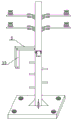
fig. 1 is a schematic structural view of a novel iron utility pole for supporting a spliced power line according to the present invention;
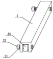
FIG. 2 is a schematic diagram of a fixing rod structure according to the present invention;
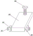
FIG. 3 is a schematic structural view of a fastening device according to the present invention;
FIG. 4 is a schematic view of the structure of the extension rod hanging down according to the present invention;
in the figure: 1. a base; 2. climbing a ladder; 3. fixing the rod; 4. fastening a bolt; 5. fixing the clamping plate; 6. a porcelain bottle; 7. a connecting plate; 8. a fastening device; 9. a rotating shaft; 10. a rod body; 11. A fixing hole; 12. fixing a bracket; 31. a threaded rod; 32. a nut; 33. an extension rod; 81. A fixed head; 82. a fixed seat; 83. a fastening plate; 84. fixing screws; 85. a connecting rod.
Detailed Description
The technical solutions in the embodiments of the present invention will be clearly and completely described below with reference to the drawings in the embodiments of the present invention, and it is obvious that the described embodiments are only a part of the embodiments of the present invention, and not all of the embodiments. All other embodiments, which can be derived by a person skilled in the art from the embodiments given herein without making any creative effort, shall fall within the protection scope of the present invention.
In the description of the present invention, it should be noted that the terms "upper", "lower", "inner", "outer", "front", "rear", "both ends", "one end", "the other end", and the like indicate orientations or positional relationships based on those shown in the drawings, and are only for convenience of description and simplicity of description, but do not indicate or imply that the referred device or element must have a specific orientation, be constructed in a specific orientation, and be operated, and thus, should not be construed as limiting the present invention. Furthermore, the terms "first" and "second" are used for descriptive purposes only and are not to be construed as indicating or implying relative importance.
In the description of the present invention, it is to be noted that, unless otherwise explicitly specified or limited, the terms "mounted," "disposed," "connected," and the like are to be construed broadly, and for example, "connected" may be a fixed connection, a detachable connection, or an integral connection; can be mechanically or electrically connected; they may be connected directly or indirectly through intervening media, or they may be interconnected between two elements. The specific meanings of the above terms in the present invention can be understood in specific cases to those skilled in the art.
Referring to fig. 1-4, the present invention provides a technical solution: the utility model provides a novel pin-connected panel power line supports uses iron wire pole structure, be provided with fixed orifices 11 including base 1 and fixed orifices 11 base 1 upper right corner, base 1 middle part top is provided with the body of rod 10, body of rod 10 lower extreme is provided with fixed bolster 12, fixed bolster 12 top is provided with ladder 2 of ascending a height, ladder 2 top of ascending a height is provided with fastener 8, fastener 8 rear is provided with pivot 9, pivot 9 top left side is provided with dead lever 3, dead lever 3 top right side is provided with solid fixed splint 5, gu fixed splint 5 right-hand member top is provided with fastening bolt 4, fastening bolt 4 right side is provided with connecting plate 7, connecting plate 7 right-hand member top is provided with vase 6, dead lever 3 includes threaded rod 31, nut 32 and extension rod 33, nut 32 right side is provided with threaded rod 31, threaded rod 31 right side is provided with extension rod 33, fastener 8 includes fixed head 81, Fixing base 82, mounting plate 83, fixed screw 84 and connecting rod 85, the connecting rod 85 left side is provided with mounting plate 83, and mounting plate 83 left side is provided with fixing base 82, and fixing base 82 left side is provided with fixed head 81, and mounting plate 83 upper end middle part is provided with fixed screw 84.
The utility model provides a novel pin-connected panel power line supports uses iron wire pole structure, it is provided with five altogether to ascend a height ladder 2, five ascend a height ladder 2 size is the same, it is connected with the body of rod 10 through welded mode to ascend a height ladder 2, body of rod 10 lower extreme left side sets up three 2 right sides of ascending a height ladder and sets up two ladder 2 of ascending a height, body of rod 10 sets up to two parts altogether, body of rod 10 lower part top is connected with pivot 9 through welded mode, body of rod 10 first part can cup joint and rotate in pivot 9, it conveniently scrambles when needs are adjusted to set up five ladder 2 of ascending a height.
The utility model provides a novel pin-connected panel power line supports uses iron wire pole structure, fastening bolt 4, solid fixed splint 5, vase 6 and connecting plate 7 are provided with four respectively, and four fastening bolt 4, solid fixed splint 5, vase 6 and connecting plate 7 size equal scale are the same, and the body of rod 10 upper end left and right sides sets up two fastening bolt 4, solid fixed splint 5, vase 6 and connecting plate 7 respectively. The left end of the fixed splint 5 is connected with the rod body 10 in a welding mode, the connecting plate 7 extends into the fixed splint 5 and is fixed by the fastening bolt 4 penetrating through the fixed splint 5 and the connecting plate 7, and four integral functions of the telegraph pole are guaranteed.
The utility model provides a novel pin-connected panel power line supports uses iron wire pole structure, fixed orifices 11 are provided with four altogether, and 11 small and large-scale homogeneous phases in four fixed orifices, and 1 four angles of base all are provided with fixed orifices 11. Fixed bolster 12 is provided with four altogether, and four fixed bolsters 12 are the same on a large scale, all is provided with fixed bolster 12 around the body of rod 10 lower extreme, and fixed bolster 12 is connected with the body of rod 10 through the welded mode, and fixed bolster 12 below is connected fixed bolster 12 welded mode more firm through welded mode and base 1, and the fixed orifices 11 set up make base 1 fix on four angles of base more stable when subaerial.
The utility model provides a novel pin-connected panel power line supports uses iron wire pole structure, threaded rod 31 and nut 32 all are provided with two, two threaded rods 31 and nut 32 are big or small scale homogeneous phase, both ends all are provided with threaded rod 31 and nut 32 about dead lever 3, threaded rod 31 only has the left end to be provided with the screw thread, threaded rod 31 passes dead lever 3 and extension rod 33 and makes it fixed, two threaded rods 31 and nut 32 make dead lever 3 and extension rod 33 more stable, threaded rod 31 middle part does not have the regulation that the screw thread makes things convenient for extension rod 33.
The utility model provides a novel pin-connected panel power line supports uses iron wire pole structure, fixed head 81 and fixing base 82 all are provided with two, and two fixed heads 81 are the same with the big or small scale homogeneous phase of fixing base 82, and the mounting plate 83 front end left and right sides all is provided with fixed head 81 and fixing base 82, and fixed head 81 and fixing base 82 set up two respectively and make its mounting plate 83 more stable about mounting plate 83 both ends.
The working principle and the using process of the utility model are as follows: after the device is installed, the base 1 is placed at a proper position, then four corners of the base 1 are fixed through the fixing holes 11, the lower end of the rod body 10 is connected with the base 1 and the rod body 10 through the fixing support 12 in a welding mode, a cable penetrates through the porcelain bottle 6, the porcelain bottle 6 is arranged above the connecting plate 7, the fastening bolt 4 penetrates through the fixing clamping plate 5 and is fixed, the stability of the connecting plate 7 is ensured, when the direction of the upper end of the rod body 10 needs to be adjusted, the fixing ladder 2 climbs to the middle of the rod body 10 to dismount a fixing screw 84 in the fastening device 8, the fixing screw 84 penetrates through the fastening plate 83 and is fixed on the rod body 10, the left side and the right side of the upper end of the fastening device 8 are provided with the fixing seats 82 and the fixing heads 81 which are connected through the connecting rod 85, the fastening plate 83 clings to the rotating shaft 9, the fixing screw 84 is fixed below the rotating shaft 9, the connecting rod 85 penetrates through the fastening plate 83 and is fixed above the rotating shaft 9, the fixing screw 84 is removed and then the threaded rod 31 and the nut 32 at the right end of the fixing rod 3 are removed, at the moment, the extension rod 33 inside the fixing rod 3 is in a movable body, the extension rod 33 inside the fixing rod is lowered through the threaded rod 31 at the left end to be in a vertical body, then the base 1 is lifted from the upper part to the lower part of the ascending ladder 2, and the orientation of the upper end of the rod body 10 can be changed by tightly holding the extension rod 33 to rotate around the rod body 10.
Although embodiments of the present invention have been shown and described, it will be appreciated by those skilled in the art that changes, modifications, substitutions and alterations can be made in these embodiments without departing from the principles and spirit of the utility model, the scope of which is defined in the appended claims and their equivalents.
Claims (8)
1. The utility model provides a novel pin-connected panel power line supports uses iron wire pole structure, includes base (1) and fixed orifices (11) its characterized in that: the lifting device is characterized in that a fixing hole (11) is formed in the upper right corner of the base (1), a rod body (10) is arranged above the middle of the base (1), a fixing support (12) is arranged at the lower end of the rod body (10), a climbing ladder (2) is arranged above the fixing support (12), a fastening device (8) is arranged above the climbing ladder (2), a rotating shaft (9) is arranged behind the fastening device (8), a fixing rod (3) is arranged on the left side above the rotating shaft (9), a fixing clamp plate (5) is arranged on the right side above the fixing rod (3), a fastening bolt (4) is arranged above the right end of the fixing clamp plate (5), a connecting plate (7) is arranged on the right side of the fastening bolt (4), a porcelain bottle (6) is arranged above the right end of the connecting plate (7), and the fixing rod (3) comprises a threaded rod (31), a nut (32) and an extension rod (33), nut (32) right side is provided with threaded rod (31), threaded rod (31) right side is provided with extension rod (33), fastener (8) are including fixed head (81), fixing base (82), mounting plate (83), fixed screw (84) and connecting rod (85), connecting rod (85) left side is provided with mounting plate (83), mounting plate (83) left side is provided with fixing base (82), fixing base (82) left side is provided with fixed head (81), mounting plate (83) upper end middle part is provided with fixed screw (84).
2. The novel iron utility pole structure for supporting the assembled power line of claim 1, which is characterized in that: climb ladder (2) and be provided with five altogether climb ladder (2) big or small scale homogeneous phase the same, it is connected with the body of rod (10) through the welded mode to ascend ladder (2), body of rod (10) lower extreme left side sets up three ladder (2) right side of ascending ladder and sets up two ladder (2) of ascending ladder, two parts of the body of rod (10), body of rod (10) lower part top is connected with pivot (9) through the welded mode, the first half of the body of rod (10) can insert and rotate in pivot (9).
3. The novel iron utility pole structure for supporting the assembled power line of claim 1, which is characterized in that: fastening bolt (4), solid fixed splint (5), vase (6) and connecting plate (7) are provided with four respectively, four fastening bolt (4), solid fixed splint (5), vase (6) and connecting plate (7) size scale homogeneous phase are the same, the body of rod (10) upper end left and right sides sets up two fastening bolt (4), solid fixed splint (5), vase (6) and connecting plate (7) respectively.
4. The novel iron utility pole structure for supporting the assembled power line of claim 1, which is characterized in that: the left end of the fixed clamping plate (5) is connected with the rod body (10) in a welding mode, and the connecting plate (7) stretches into the fixed clamping plate (5) and is fixed with the connecting plate (7) through the fixed clamping plate (5) by using a fastening bolt (4).
5. The novel iron utility pole structure for supporting the assembled power line of claim 1, which is characterized in that: the four fixing holes (11) are arranged, the four fixing holes (11) are identical in size and scale, and the four corners of the base (1) are provided with the fixing holes (11).
6. The novel iron utility pole structure for supporting the assembled power line of claim 1, which is characterized in that: the fixing support (12) are provided with four, the four fixing supports (12) are identical in size and scale, the fixing supports (12) are arranged at the front, back, left and right sides of the lower end of the rod body (10), the fixing supports (12) are connected with the rod body (10) in a welding mode, and the lower portion of each fixing support (12) is connected with the base (1) in a welding mode.
7. The novel iron utility pole structure for supporting the assembled power line of claim 1, which is characterized in that: threaded rod (31) and nut (32) all are provided with two, two threaded rod (31) and nut (32) size scale homogeneous phase is the same, both ends all are provided with threaded rod (31) and nut (32) about dead lever (3), threaded rod (31) only has the left end to be provided with the screw thread, dead lever (3) and extension rod (33) are passed in threaded rod (31) make it fixed.
8. The novel iron utility pole structure for supporting the assembled power line of claim 1, which is characterized in that: the fixing head (81) and the fixing seat (82) are arranged in two, the fixing head (81) and the fixing seat (82) are identical in size and scale, and the fixing head (81) and the fixing seat (82) are arranged on the left side and the right side of the front end of the fastening plate (83).
Priority Applications (1)
| Application Number | Priority Date | Filing Date | Title |
|---|---|---|---|
| CN202121936132.7U CN215889545U (en) | 2021-08-18 | 2021-08-18 | Novel iron wire pole structure for supporting assembled power line |
Applications Claiming Priority (1)
| Application Number | Priority Date | Filing Date | Title |
|---|---|---|---|
| CN202121936132.7U CN215889545U (en) | 2021-08-18 | 2021-08-18 | Novel iron wire pole structure for supporting assembled power line |
Publications (1)
| Publication Number | Publication Date |
|---|---|
| CN215889545U true CN215889545U (en) | 2022-02-22 |
Family
ID=80342800
Family Applications (1)
| Application Number | Title | Priority Date | Filing Date |
|---|---|---|---|
| CN202121936132.7U Active CN215889545U (en) | 2021-08-18 | 2021-08-18 | Novel iron wire pole structure for supporting assembled power line |
Country Status (1)
| Country | Link |
|---|---|
| CN (1) | CN215889545U (en) |
-
2021
- 2021-08-18 CN CN202121936132.7U patent/CN215889545U/en active Active
Similar Documents
| Publication | Publication Date | Title |
|---|---|---|
| CN206180456U (en) | Two pole double guide rail join in marriage electrical pillar rack | |
| CN210052611U (en) | Mounting system for transformer | |
| CN215632053U (en) | Sign combined type telegraph pole | |
| CN214227588U (en) | Portable insulation platform of ascending a height | |
| CN214741044U (en) | Ladder fixing structure is hung in electric power construction | |
| CN101232158B (en) | Equipotential operating curve ladder | |
| CN215817548U (en) | Reactive power compensator fixed bolster on post | |
| CN213391434U (en) | Electric power tower anti-climbing device convenient to enclose and close | |
| CN214860699U (en) | Transformer safety belt hanging device | |
| CN113882738A (en) | Split assembly type line pole heightening frame | |
| CN210283972U (en) | Railway power transmission line anti-winding device | |
| CN217557882U (en) | High-strength shockproof 35KV power transmission line tangent tower | |
| CN219067814U (en) | Novel rotatable high-voltage cable support | |
| CN207098441U (en) | Load transfer instrument and electric power maintenance equipment | |
| CN211555631U (en) | Transformer installing support | |
| CN221942330U (en) | Ladder fixed knot constructs is hung in electric power construction | |
| CN222162175U (en) | A transmission line transmission pole structure | |
| CN216553744U (en) | Support staple bolt of ladder is hung to multi-functional aluminum alloy | |
| CN222127608U (en) | A portable temporary power line overhead device | |
| CN216406347U (en) | Wire pole convenient to installation power equipment | |
| CN216553731U (en) | Ladder is hung to multi-functional aluminum alloy | |
| CN215758583U (en) | Scaffold for bridge maintenance | |
| CN213774771U (en) | Fabricated building construction protective structure | |
| CN223755034U (en) | A monitoring installation pole | |
| CN219980275U (en) | Power transmission line erection support with adjusting supporting structure |
Legal Events
| Date | Code | Title | Description |
|---|---|---|---|
| GR01 | Patent grant | ||
| GR01 | Patent grant |