Anti-compression anti-freezing inspection cover for toilet dirt treatment equipment
Technical Field
The utility model relates to the field of toilet sewage treatment equipment, in particular to a compression-resistant anti-freezing inspection cover for toilet sewage treatment equipment.
Background
The existing equipment for treating the toilet sewage in the market mainly comprises: the device comprises a double-vat septic tank, a three-grid septic tank, an integrated sewage treatment device, a purification tank device and the like, wherein the devices have the defects of small manhole (inspection hole) structural design, thin wall thickness, low compressive strength, incapability of deep burying and the like, and are buried in shallow depth when used in the south, so that the problem is not obvious; however, in northern cold areas, in order to solve the anti-freezing problem at low cost, the equipment must be deeply buried, the buried depth is required to be between 1 meter and 1.8 meters, and the traditional technology is to install a deep and thin shaft (anti-freezing neck) on a manhole; the deep and thin shaft not only increases the difficulty of the operation and maintenance personnel to enter and exit, but also can not reduce the pressure of the soil covering; manhole (inspection hole) have influenced technical staff's maintenance and the clear drawing of silt behind the burial depth, and earthing pressure has still caused the extrusion deformation back of equipment can not normal use, lacks the safety lock on the well lid simultaneously, opens the well lid when having children to play, takes place the risk of falling into the well.
SUMMERY OF THE UTILITY MODEL
The utility model aims to provide a compression-resistant anti-freezing inspection cover of toilet sewage treatment equipment, which solves the problem that a child can easily open an existing well cover.
The purpose of the utility model is realized by the following technical scheme: anti-compression anti-freezing inspection cover for toilet sewage treatment equipment, comprising a barrel body and an cover plate, wherein the cover plate is integrally formed at one end of the barrel body, a manhole is arranged on the cover plate, an end cover is hinged to the cover plate, the manhole passes through the end cover to be closed, and a locking piece is arranged on the cover plate.
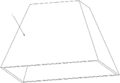
Preferably, the cylinder is in a circular truncated cone shape, a trapezoidal truncated cone shape, a square body shape or a semi-spherical shape.
Preferably, the locking piece comprises a first locking piece and a second locking piece, the end cover is locked on the cover plate through the first locking piece, and the rotating shaft of the end cover is locked in the circumferential direction through the second locking piece.
Preferably, the first locking piece comprises a locking piece A and a cylinder penetrating through the cover plate, the locking piece A is fixedly arranged at one end, located in the cylinder, of the cylinder, a groove is formed in the outer wall of the cylinder along the circumferential direction of the outer wall of the cylinder, a check ring is installed in the groove and clamped on the cover plate, and the locking piece A is clamped on the end cover by rotating the cylinder.
Preferably, the second locking piece includes a pair of ear seat and B locking piece, the pivot is rotated and is installed on the ear seat, and its both ends are located a pair of respectively the outside of ear seat, a word groove has been seted up to the one end of pivot, the B locking piece articulates on the lateral wall of ear seat, through inciting somebody to action B locking piece card is gone into a word inslot locking is died the pivot.
Preferably, the inner wall of the cylinder body is welded with a reinforcing rib, and the other end of the reinforcing rib is welded on the cover plate.
Preferably, a flange is arranged on the outer wall of the cylinder body along the circumferential direction of the cylinder body, and the flange is positioned at one end, far away from the cover plate, of the cylinder body.
Preferably, the reinforcing ribs are a plurality of and are uniformly distributed around the end cover.
The utility model has the following advantages:
1. carry out dual lock through first locking piece and second locking piece and die to the apron, avoid the apron to be opened easily to reduce and children open the apron and take place the risk of falling into the well.
2. The round platform form or trapezoidal platform form or square body form or semicircle sphere body of inspection cover has improved the bearing capacity of earth space backfill back equipment, has avoided the problem that northern area inspection socket is too little inconvenient personnel fortune dimension and sewage freezes simultaneously, has guaranteed the normal work of equipment.
Drawings
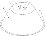
FIG. 1 is a first schematic structural diagram of the present invention;
FIG. 2 is a second schematic structural view of the present invention;
FIG. 3 is an enlarged view of a portion of FIG. 1 at A;
FIG. 4 is an enlarged view of a portion of FIG. 2 at B;
FIG. 5 is a third schematic structural view of the present invention;
FIG. 6 is a fourth schematic structural view of the present invention;
FIG. 7 is a fifth schematic structural view of the present invention;
in the figure, 1-cylinder, 2-cover plate, 3-manhole, 4-end cover, 5-A locking block, 6-cylinder, 7-retainer ring, 8-lug seat, 9-B locking block, 10-straight groove, 11-reinforcing rib and 12-flange.
Detailed Description
In order to make the objects, technical solutions and advantages of the embodiments of the present invention more apparent, the technical solutions of the embodiments of the present invention will be described clearly and completely with reference to the accompanying drawings of the embodiments of the present invention, and it is obvious that the described embodiments are some, but not all embodiments of the present invention. The components of embodiments of the present invention generally described and illustrated in the figures herein may be arranged and designed in a wide variety of different configurations.
Thus, the following detailed description of the embodiments of the present invention, presented in the figures, is not intended to limit the scope of the utility model, as claimed, but is merely representative of selected embodiments of the utility model. All other embodiments, which can be obtained by a person skilled in the art without any inventive step based on the embodiments of the present invention, are within the scope of the present invention.
In addition, the embodiments of the present invention and the features of the embodiments may be combined with each other without conflict.
It should be noted that: like reference numbers and letters refer to like items in the following figures, and thus, once an item is defined in one figure, it need not be further defined and explained in subsequent figures.
In the description of the present invention, it should be noted that the terms "center", "upper", "lower", "left", "right", "vertical", "horizontal", "inner", "outer", and the like indicate orientations or positional relationships based on the orientations or positional relationships shown in the drawings, or orientations or positional relationships that are conventionally placed when the products of the present invention are used, or orientations or positional relationships that are conventionally understood by those skilled in the art, and are used only for convenience of describing the present invention and simplifying the description, but do not indicate or imply that the device or element that is referred to must have a specific orientation, be constructed in a specific orientation, and be operated, and thus, should not be construed as limiting the present invention. Furthermore, the terms "first," "second," and the like are used merely to distinguish one description from another, and are not to be construed as indicating or implying relative importance.
In the description of the present invention, it should also be noted that, unless otherwise explicitly specified or limited, the terms "disposed," "mounted," "connected," and "connected" are to be construed broadly and may, for example, be fixedly connected, detachably connected, or integrally connected; can be mechanically or electrically connected; they may be connected directly or indirectly through intervening media, or they may be interconnected between two elements. The specific meanings of the above terms in the present invention can be understood in specific cases to those skilled in the art.
As shown in fig. 1-4, the anti-compression anti-freezing inspection cover for toilet dirt processing equipment comprises a cylinder body 1 and a cover plate 2, wherein the cover plate 2 is integrally formed at one end of the cylinder body 1, a manhole 3 is arranged on the cover plate 2, an end cover 4 is hinged on the cover plate 2, the manhole 3 is opened and closed through the end cover 4, a first locking piece and a second locking piece are arranged on the cover plate 2, the end cover 4 is locked on the cover plate 2 through the first locking piece, the further first locking piece comprises an A locking piece 5 and a cylinder 6 penetrating through the cover plate 2, the A locking piece 5 is fixedly arranged at one end of the cylinder 6 in the cylinder body 1, a groove is arranged on the outer wall of the cylinder 6 along the circumferential direction, a retaining ring 7 is arranged in the groove, the retaining ring 7 is clamped on the cover plate 2, the A locking piece 5 is clamped on the end cover 4 through rotating the cylinder 6, the circumferential direction of a rotating shaft of the end cover 4 is locked through the second locking piece, the further second locking piece comprises a pair of an ear seat 8 and a B locking piece 9, the pivot is rotated and is installed on ear seat 8, and its both ends are located a pair of ear seat 8's the outside respectively, a word groove 10 has been seted up to the one end of pivot, and B locking piece 9 articulates on ear seat 8's lateral wall, through going into the dead pivot of a word inslot 10 lock with B locking piece 9 card, carries out dual lock through first locking piece and second locking piece to apron 2 and dies, avoids apron 2 to be opened easily to reduce and children open the risk that apron 2 takes place to fall into the well.
In this embodiment, as shown in fig. 1 to 7, the barrel 1 is in a circular truncated cone shape, a trapezoidal truncated cone shape, a square body shape or a semi-sphere shape, the cover plate 2 is located at the small end of the barrel 1, the reinforcing ribs 11 are welded on the inner wall of the barrel 1, the other ends of the reinforcing ribs 11 are welded on the cover plate 2, the reinforcing ribs 11 are a plurality of and are uniformly distributed around the end cover 4, the bearing capacity of the cover plate 2 is enhanced, and the influence on the use of the cover body caused by the deformation of a heavy vehicle is reduced.
In this embodiment, as shown in fig. 1 and 2, a flange 12 is arranged on the outer wall of the cylinder 1 along the circumferential direction, the flange 12 is located at one end of the cylinder 1 far away from the cover plate 2, the cover body is placed on the equipment, the outer diameter of the cylinder 1 is larger than the bearing surface of the equipment, the height of the cylinder 1 is determined by the depth of the frozen soil layer, then the cover body is fixed on the equipment by using bolts or pressing blocks, the structure is simple, the installation is convenient, and the cover body is prevented from being dislocated with the equipment in the soil covering process and affecting the use of the cover body.
Although the present invention has been described in detail with reference to the foregoing embodiments, it will be apparent to those skilled in the art that various changes in the embodiments and/or modifications of the utility model can be made, and equivalents and modifications of some features of the utility model can be made without departing from the spirit and scope of the utility model.