CN215842313U - Bag-type dust collector - Google Patents
Bag-type dust collector Download PDFInfo
- Publication number
- CN215842313U CN215842313U CN202122359342.0U CN202122359342U CN215842313U CN 215842313 U CN215842313 U CN 215842313U CN 202122359342 U CN202122359342 U CN 202122359342U CN 215842313 U CN215842313 U CN 215842313U
- Authority
- CN
- China
- Prior art keywords
- groove body
- edge
- square groove
- bag
- fixedly connected
- Prior art date
- Legal status (The legal status is an assumption and is not a legal conclusion. Google has not performed a legal analysis and makes no representation as to the accuracy of the status listed.)
- Expired - Fee Related
Links
- 239000000428 dust Substances 0.000 title claims abstract description 44
- 239000004744 fabric Substances 0.000 claims description 10
- 210000005056 cell body Anatomy 0.000 claims description 8
- 238000009423 ventilation Methods 0.000 claims description 7
- UGFAIRIUMAVXCW-UHFFFAOYSA-N Carbon monoxide Chemical compound [O+]#[C-] UGFAIRIUMAVXCW-UHFFFAOYSA-N 0.000 description 6
- 230000009471 action Effects 0.000 description 6
- 239000003546 flue gas Substances 0.000 description 6
- 239000007789 gas Substances 0.000 description 4
- 230000005484 gravity Effects 0.000 description 4
- 238000000034 method Methods 0.000 description 4
- 238000004062 sedimentation Methods 0.000 description 4
- 238000001914 filtration Methods 0.000 description 3
- 230000000694 effects Effects 0.000 description 2
- 239000002245 particle Substances 0.000 description 2
- 230000008569 process Effects 0.000 description 2
- 239000000779 smoke Substances 0.000 description 2
- 241001391944 Commicarpus scandens Species 0.000 description 1
- 230000004075 alteration Effects 0.000 description 1
- 230000009286 beneficial effect Effects 0.000 description 1
- 238000004140 cleaning Methods 0.000 description 1
- 238000007599 discharging Methods 0.000 description 1
- 239000000835 fiber Substances 0.000 description 1
- 230000007246 mechanism Effects 0.000 description 1
- 230000004048 modification Effects 0.000 description 1
- 238000012986 modification Methods 0.000 description 1
- 238000006467 substitution reaction Methods 0.000 description 1
Images


Landscapes
- Filtering Of Dispersed Particles In Gases (AREA)
Abstract
The utility model relates to the technical field of dust removal devices, and particularly discloses a bag-type dust remover, wherein the top and bottom ends of a cylindrical barrel are respectively connected with the bottom surface of an upper square groove body and the top surface of a lower square groove body, the edge of the top end of the upper square groove body is connected with the edge of the bottom end of a middle box body, the edge of the bottom end of the lower square groove body is connected with the edge of the top end of an ash bucket, the top ends of supporting legs are connected with the side surface of the upper square groove body, a bag is arranged in the inner cavity of the middle box body, an air inlet pipe is arranged at the front end of the cylindrical barrel, a circular groove body is arranged in the cylindrical barrel, an annular cavity is formed between the circular groove body and the cylindrical barrel, the edge of an opening at the top of the circular groove body is connected with the inner edge of the bottom surface of the inner cavity of the upper square groove body, the outer edge of the bottom end of the annular cavity is connected with the inner edge of the top surface of the inner cavity of the lower square groove body, a plurality of through holes are uniformly formed in the side wall of the circular groove body along the annular shape, and the through holes are staggered with the inner end of the air inlet pipe; the problem that dust-containing air discharged from an air inlet pipe in a bag-type dust collector cannot be uniformly distributed to each bag is solved.
Description
Technical Field
The utility model relates to the technical field of dust removal devices, in particular to a bag-type dust remover.
Background
Among the dust removing devices, the bag dust collector is a dry type dust filtering device. It is suitable for trapping fine, dry, non-fibrous dust. The bag-type dust collector mainly comprises an upper box body, a middle box body, an ash bucket, an ash cleaning system, an ash discharging mechanism and the like; the cloth bag is arranged in the middle box body and is made of woven filter cloth or non-woven felt, the dust-containing gas is filtered by utilizing the filtering action of the fiber fabric, after the dust-containing gas enters the bag type dust collector, the dust with large particles and large specific gravity falls into the dust hopper due to the sedimentation of the gravity, and the dust is blocked when the gas containing fine dust passes through the cloth bag, so that the gas is purified.
The existing bag-type dust remover sends air containing dust into the box body through the air inlet pipe, the bag used for removing dust in the box body is provided with a plurality of bags, the air inlet flow rate of the bag close to the air inlet pipe is larger, and the impact received by the bag is also more severe, so that the bag is easy to break, but the air inlet flow rate of the bag far away from the air inlet pipe is smaller, and the filtering efficiency of the bag cannot be fully utilized.
SUMMERY OF THE UTILITY MODEL
The utility model aims to provide a bag-type dust collector, which is used for solving the problem that dust-containing air exhausted by an air inlet pipe in the conventional bag-type dust collector cannot be uniformly distributed to each bag.
In order to achieve the purpose, the utility model provides the following technical scheme: the bag-type dust collector comprises an upper box body, a middle box body, an ash bucket, supporting legs, a cloth bag and an air distribution shell, wherein the air distribution shell comprises an upper square groove body, a cylindrical barrel body and a lower square groove body, the top and bottom ends of the cylindrical barrel body are respectively fixedly connected with the bottom surface of the upper square groove body and the top surface of the lower square groove body, the edge of the top end of the upper square groove body is fixedly connected with the edge of the bottom end of the middle box body, the edge of the bottom end of the lower square groove body is fixedly connected with the edge of the top end of the ash bucket, the top end of the supporting leg is fixedly connected with the side surface of the upper square groove body, the cloth bag is arranged in the inner cavity of the middle box body, the front end of the cylindrical barrel body is provided with an air inlet pipe, a circular groove body is arranged in the cylindrical barrel body, an annular cavity is formed between the circular groove body and the cylindrical barrel body, and the edge of the top opening of the circular groove body is connected with the inner edge of the bottom surface of the inner cavity of the upper square groove body, the outer fringe of annular cavity bottom with the inner edge of square cell body inner chamber top surface is connected down, a plurality of clearing holes have evenly been seted up along the annular to the lateral wall of circular cell body, just the clearing hole with stagger in the inner end of air-supply line.
Preferably, the outer side wall of the circular groove body corresponds to one side, far away from the air inlet pipe through the through holes, of the air inlet pipe, and a guide plate is fixedly connected to the outer side wall of the circular groove body, and the width of the guide plate is gradually increased from near to far in the directions of the two sides of the air inlet pipe.
Preferably, the inner side wall of the circular groove body is fixedly connected with ventilation pipes respectively at positions corresponding to the through holes, and central axes of the ventilation pipes extend along the tangential direction of the inner cavity of the circular groove body respectively.
Preferably, the bottom surface of the upper groove body is provided with an annular inclined surface at the periphery of the top end of the circular groove body, and the inner edge of the annular inclined surface is lower than the outer edge of the annular inclined surface.
Preferably, the front end and the rear end of the two side faces of the upper square groove body are respectively and fixedly connected with a supporting block, and the top ends of the supporting legs are respectively and correspondingly fixedly connected with the supporting blocks.
Compared with the prior art, the utility model has the beneficial effects that:
when the bag-type dust collector is used, dust-containing smoke enters the annular cavity from the air inlet pipe for preliminary sedimentation, then enters the circular groove body through the through holes, and then is diffused to the bottom of the bag through the upper square groove body, so that the effect of uniformly distributing the dust-containing smoke to the bag is achieved.
Drawings
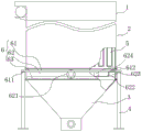
FIG. 1 is a schematic overall front view of the present invention;
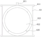
FIG. 2 is a schematic top view of the air distribution housing of the present invention;
FIG. 3 is a schematic bottom view of the air distribution housing of the present invention;
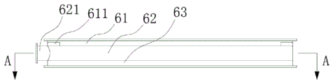
FIG. 4 is a schematic side view of the air distribution casing of the present invention
FIG. 5 is a schematic sectional view of the structure of FIG. 4A-A according to the present invention.
In the figure: 1-upper box body; 2-middle box body; 3-ash bucket; 4-a support leg; 5-cloth bag; 6-air distribution shell; 61-upper square groove body; 611-supporting block; 612-annular inclined surface; 62-a cylindrical barrel; 621-air inlet pipe; 622-circular groove body; 623-an annular cavity; 624-ventilation pipe; 625-a flow guide plate; 626-through the hole; 63-lower square trough body.
Detailed Description
The technical solutions in the embodiments of the present invention will be clearly and completely described below with reference to the drawings in the embodiments of the present invention, and it is obvious that the described embodiments are only a part of the embodiments of the present invention, and not all of the embodiments. All other embodiments, which can be derived by a person skilled in the art from the embodiments given herein without making any creative effort, shall fall within the protection scope of the present invention.
Referring to fig. 1-5, the present invention provides a technical solution: the bag-type dust collector comprises an upper box body 1, a middle box body 2, an ash bucket 3, supporting legs 4, a bag 5 and an air distribution shell 6, wherein the air distribution shell 6 comprises an upper square groove body 61, a cylindrical barrel body 62 and a lower square groove body 63, the top and bottom ends of the cylindrical barrel body 62 are respectively fixedly connected with the bottom surface of the upper square groove body 61 and the top surface of the lower square groove body 63, the edge of the top end of the upper square groove body 61 is fixedly connected with the edge of the bottom end of the middle box body 2, the edge of the bottom end of the lower square groove body 63 is fixedly connected with the edge of the top end of the ash bucket 3, the top end of the supporting leg 4 is fixedly connected with the side surface of the upper square groove body 61, the bag 5 is arranged in the inner cavity of the middle box body 2, an air inlet pipe 621 is arranged at the front end of the cylindrical barrel body 62, a circular groove body 622 is arranged in the cylindrical barrel body 62, an annular cavity 623 is formed between the circular groove body 622 and the cylindrical barrel body 62, the edge of the top opening of the circular groove body 622 is connected with the inner edge of the bottom surface of the upper square groove body 61, the outer edge of the bottom end of the annular cavity 623 is connected with the inner edge of the top surface of the inner cavity of the lower square groove body 63, a plurality of through holes 626 are uniformly formed in the side wall of the circular groove body 622 along the annular shape, and the through holes 626 are staggered with the inner end of the air inlet pipe 621.
In this embodiment, the guide plate 625 is fixedly connected to one side of the outer side wall of the circular slot 622, which is far away from the air inlet pipe 621 through the corresponding through hole 626, and the width of the guide plate 625 in the direction of the two sides of the air inlet pipe 621 gradually increases from near to far.
In this embodiment, the positions of the inner side wall of the circular groove 622 corresponding to the through holes 626 are respectively and fixedly connected with a ventilation pipe 624, and the central axes of the ventilation pipes 624 respectively extend along the tangential direction of the inner cavity of the circular groove 622.
In this embodiment, the bottom surface of the upper groove 61 is provided with an annular inclined surface 612 at the periphery of the top end of the circular groove 622, and the inner edge of the annular inclined surface 612 is lower than the outer edge thereof.
In this embodiment, the front end and the rear end of the two side surfaces of the upper groove body 61 are respectively and fixedly connected with a supporting block 611, and the top ends of the supporting legs 4 are respectively and correspondingly and fixedly connected with the supporting blocks 611.
The working principle is as follows: when the dust-containing flue gas sedimentation tank is used, the dust-containing flue gas enters the annular cavity 623 from the air inlet pipe 621, the dust-containing flue gas is subjected to preliminary sedimentation in the annular cavity 623, and dust with large particles and large specific gravity is settled under the action of gravity and falls into the dust hopper 3 through the inner cavity of the lower square groove body 63; the flue gas containing the fine dust enters the inner cavity of the circular groove body 622 through the through hole 626 and the air inlet pipe 624 under the guiding action of the guide plate 625, and the flue gas in the inner cavity of the circular groove body 622 is diffused to the bottom of the cloth bag 5 through the annular inclined surface 612 and the upper groove body 61, so that the effect of uniformly distributing the flue gas containing the dust to the cloth bag 5 is achieved.
It is noted that, herein, relational terms such as first and second, and the like may be used solely to distinguish one entity or action from another entity or action without necessarily requiring or implying any actual such relationship or order between such entities or actions. Also, the terms "comprises," "comprising," or any other variation thereof, are intended to cover a non-exclusive inclusion, such that a process, method, article, or apparatus that comprises a list of elements does not include only those elements but may include other elements not expressly listed or inherent to such process, method, article, or apparatus.
Although embodiments of the present invention have been shown and described, it will be appreciated by those skilled in the art that changes, modifications, substitutions and alterations can be made in these embodiments without departing from the principles and spirit of the utility model, the scope of which is defined in the appended claims and their equivalents.
Claims (5)
1. The sack cleaner, including upper portion box (1), middle part box (2), ash bucket (3), landing leg (4) and sack (5), its characterized in that: the dust collector also comprises an air distribution shell (6), wherein the air distribution shell (6) comprises an upper square groove body (61), a cylindrical barrel body (62) and a lower square groove body (63), the top bottom end of the cylindrical barrel body (62) is fixedly connected with the bottom surface of the upper square groove body (61) and the top surface of the lower square groove body (63) respectively, the edge of the top end of the upper square groove body (61) is fixedly connected with the edge of the bottom end of the middle box body (2), the edge of the bottom end of the lower square groove body (63) is fixedly connected with the edge of the top end of the dust hopper (3), the top ends of the supporting legs (4) are fixedly connected with the side surface of the upper square groove body (61), the cloth bag (5) is arranged in the inner cavity of the middle box body (2), the front end of the cylindrical barrel body (62) is provided with an air inlet pipe (621), and a circular groove body (622) is arranged in the cylindrical barrel body (62), circular cell body (622) with form annular cavity (623) between cylinder barrel (62), the open edge in circular cell body (622) top with the inner edge of last square cell body (61) inner chamber bottom surface is connected, the outer fringe of annular cavity (623) bottom with the inner edge of below square cell body (63) inner chamber top surface is connected, a plurality of clearing holes (626) have evenly been seted up along the annular to the lateral wall of circular cell body (622), just clearing hole (626) with the inner end of air-supply line (621) staggers.
2. The bag-type dust collector of claim 1, wherein: circular cell body (622) lateral wall correspond keep away from in through hole (626) one side fixedly connected with guide plate (625) of air-supply line (621), on air-supply line (621) both sides direction the width of guide plate (625) is from near to far gradually increasing.
3. The bag-type dust collector of claim 2, wherein: the positions of the inner side wall of the circular groove body (622) corresponding to the through holes (626) are respectively and fixedly connected with a ventilation pipe (624), and the central axis of the ventilation pipe (624) respectively extends along the tangential direction of the inner cavity of the circular groove body (622).
4. The bag-type dust collector of claim 1, wherein: an annular inclined surface (612) is arranged at the position, located on the periphery of the top end of the circular groove body (622), of the bottom surface of the upper square groove body (61), and the inner edge of the annular inclined surface (612) is lower than the outer edge of the annular inclined surface.
5. The bag-type dust collector of claim 1, wherein: the front end and the rear end of the two side faces of the upper square groove body (61) are respectively and fixedly connected with a supporting block (611), and the top ends of the supporting legs (4) are respectively and correspondingly fixedly connected with the supporting blocks (611).
Priority Applications (1)
| Application Number | Priority Date | Filing Date | Title |
|---|---|---|---|
| CN202122359342.0U CN215842313U (en) | 2021-09-28 | 2021-09-28 | Bag-type dust collector |
Applications Claiming Priority (1)
| Application Number | Priority Date | Filing Date | Title |
|---|---|---|---|
| CN202122359342.0U CN215842313U (en) | 2021-09-28 | 2021-09-28 | Bag-type dust collector |
Publications (1)
| Publication Number | Publication Date |
|---|---|
| CN215842313U true CN215842313U (en) | 2022-02-18 |
Family
ID=80262038
Family Applications (1)
| Application Number | Title | Priority Date | Filing Date |
|---|---|---|---|
| CN202122359342.0U Expired - Fee Related CN215842313U (en) | 2021-09-28 | 2021-09-28 | Bag-type dust collector |
Country Status (1)
| Country | Link |
|---|---|
| CN (1) | CN215842313U (en) |
-
2021
- 2021-09-28 CN CN202122359342.0U patent/CN215842313U/en not_active Expired - Fee Related
Similar Documents
| Publication | Publication Date | Title |
|---|---|---|
| CN207137572U (en) | A kind of cloth bag automatic cleaning apparatus of new sack cleaner | |
| CN203355545U (en) | Cyclone bag-type composite dust collector | |
| CN101254381A (en) | Dust collection method using pipeline sedimentation and dust removing equipment | |
| CN203816379U (en) | Low-pressure pulse-jet bag dust collector | |
| CN212790180U (en) | Bag collector with dust self-cleaning function | |
| CN105903276A (en) | Dust falling device | |
| CN219376575U (en) | Cloth bag dust remover | |
| CN219355621U (en) | Air distribution device for bag dust collector | |
| CN216092684U (en) | Dehumidification type bag-type dust collector | |
| CN215462766U (en) | Pulse jetting device of bag-type dust collector | |
| CN209885425U (en) | A bag filter | |
| CN214680632U (en) | Quick-dedusting bag-type dust remover blowing device | |
| CN211328549U (en) | Pulse dust collector | |
| CN210845605U (en) | Multi-angle air supply bag type dust collector | |
| CN211725204U (en) | Dust remover of protection sack design | |
| CN210138533U (en) | Energy-saving soda ash furnace sack cleaner | |
| CN209490635U (en) | A kind of deduster | |
| CN209155353U (en) | A kind of bag-type dust collector of wood industry | |
| CN216259636U (en) | Bag collector is used in auto-parts production | |
| CN211659545U (en) | Pulse dust collector | |
| CN218421763U (en) | Dust remover convenient to clearance | |
| CN204933107U (en) | A kind of high-efficiency cloth bag dust arrester | |
| CN205760253U (en) | A kind of inverse type catalysis filter bag decomposing two English | |
| CN221906214U (en) | Pulse bag type dust collector for mineral separation | |
| CN214019698U (en) | Portable sack cleaner suitable for traditional chinese medicine workshop |
Legal Events
| Date | Code | Title | Description |
|---|---|---|---|
| GR01 | Patent grant | ||
| GR01 | Patent grant | ||
| CF01 | Termination of patent right due to non-payment of annual fee | ||
| CF01 | Termination of patent right due to non-payment of annual fee |
Granted publication date: 20220218 |