CN215842011U - Water inlet self-cleaning valve for storage tank - Google Patents
Water inlet self-cleaning valve for storage tank Download PDFInfo
- Publication number
- CN215842011U CN215842011U CN202122267120.6U CN202122267120U CN215842011U CN 215842011 U CN215842011 U CN 215842011U CN 202122267120 U CN202122267120 U CN 202122267120U CN 215842011 U CN215842011 U CN 215842011U
- Authority
- CN
- China
- Prior art keywords
- cavity
- rotating shaft
- storage tank
- self
- shell
- Prior art date
- Legal status (The legal status is an assumption and is not a legal conclusion. Google has not performed a legal analysis and makes no representation as to the accuracy of the status listed.)
- Active
Links
- 238000004140 cleaning Methods 0.000 title claims abstract description 32
- XLYOFNOQVPJJNP-UHFFFAOYSA-N water Substances O XLYOFNOQVPJJNP-UHFFFAOYSA-N 0.000 title claims abstract description 30
- 238000003860 storage Methods 0.000 title claims abstract description 27
- 230000005540 biological transmission Effects 0.000 claims abstract description 17
- 238000001914 filtration Methods 0.000 claims abstract description 11
- 238000007790 scraping Methods 0.000 claims description 14
- 239000012535 impurity Substances 0.000 claims description 12
- 239000010865 sewage Substances 0.000 claims description 12
- 239000010813 municipal solid waste Substances 0.000 claims description 4
- 238000005520 cutting process Methods 0.000 claims description 3
- 230000010354 integration Effects 0.000 abstract description 2
- 238000005202 decontamination Methods 0.000 abstract 1
- 230000003588 decontaminative effect Effects 0.000 abstract 1
- 230000000694 effects Effects 0.000 description 2
- 230000001105 regulatory effect Effects 0.000 description 2
- 238000007599 discharging Methods 0.000 description 1
- 230000009977 dual effect Effects 0.000 description 1
- 239000000463 material Substances 0.000 description 1
- 238000000034 method Methods 0.000 description 1
- 230000001376 precipitating effect Effects 0.000 description 1
- 238000004064 recycling Methods 0.000 description 1
- 238000005201 scrubbing Methods 0.000 description 1
- 238000007789 sealing Methods 0.000 description 1
- 238000003466 welding Methods 0.000 description 1
Images



Landscapes
- Filtration Of Liquid (AREA)
Abstract
The utility model discloses a water inlet self-cleaning valve for a regulation and storage tank, which comprises: the device comprises a shell, a water inlet pipe, a water outlet pipe and a water outlet pipe, wherein the shell is provided with an overflowing cavity for water inlet, the middle part of the overflowing cavity is communicated with a filtering cavity for decontamination, and a central axis of the filtering cavity is arranged outside the overflowing cavity; the flow control assembly is arranged at the inlet end of the overflowing cavity; a self-cleaning assembly, comprising: the follow-up rotating blade is arranged at the outlet end of the overflowing cavity and is provided with a radial rotating shaft which is vertical to the overflowing cavity, and the radial rotating shaft penetrates out of the shell; the filter screen plate is arranged in the filter cavity, a horizontal rotating shaft is arranged at the center of the filter screen plate, and the horizontal rotating shaft penetrates out of the shell; and the transmission mechanism is provided with a first connecting end connected with the radial rotating shaft and a second connecting end connected with the horizontal rotating shaft. The utility model has smart structure, can realize the integration of water control, filtration and autonomous cleaning, avoids a large amount of cleaning work and lightens the labor intensity of workers.
Description
Technical Field
The utility model relates to the technical field of self-cleaning regulating valves, in particular to a water inlet self-cleaning valve for a regulating and storing tank.
Background
The regulation and storage pool is a rainwater collection facility, and can be a special artificial structure, such as an overground reservoir and an underground concrete pool, or a natural place or an existing facility, such as a river channel, a pond, an artificial lake, a landscape pool and the like. The regulation and storage pool is mainly used for drainage scheduling, namely temporarily storing the peak flow of the rainwater runoff in the regulation and storage pool, and slowly discharging rainwater after the maximum flow is reduced, so that the dual purposes of avoiding rainwater flood peaks and recycling rainwater are achieved. When only a common gate valve is arranged on a water inlet pipeline of the storage tank, sundries mixed in rainwater cannot be effectively filtered, and the sundries can be deposited at the bottom of the storage tank after entering the storage tank along with the rainwater, so that more manpower and material resources are needed for cleaning; if set up the filter before the gate valve, though can prevent debris entering regulation pond, nevertheless because clearance filter work is too frequent, not only influences the normal intaking in regulation pond, increased staff's intensity of labour moreover by a wide margin.
Disclosure of Invention
In order to solve the problems, the utility model provides a water inlet self-cleaning valve for a storage tank, which can realize a filtering self-cleaning function, and the following technical scheme can be adopted specifically:
the utility model relates to a water inlet self-cleaning valve for a storage tank, which comprises
The sewage treatment device comprises a shell, a sewage treatment device and a sewage treatment device, wherein the shell is provided with an overflowing cavity for water inflow, the middle part of the overflowing cavity is communicated with a filtering cavity for removing sewage, and the central axis of the filtering cavity is arranged on the outer side of the overflowing cavity;
the flow control assembly is arranged at the inlet end of the overflowing cavity;
self-cleaning assembly comprising
The follow-up rotating blade is arranged at the outlet end of the overflowing cavity and is provided with a radial rotating shaft which is vertical to the overflowing cavity, and the radial rotating shaft penetrates out of the shell;
the filter screen plate is arranged in the filter cavity, a horizontal rotating shaft is arranged at the center of the filter screen plate, and the horizontal rotating shaft penetrates out of the shell;
and the transmission mechanism is provided with a first connecting end connected with the radial rotating shaft and a second connecting end connected with the horizontal rotating shaft.
The end of the overflowing cavity is provided with a flange plate used for connecting a water inlet pipe of the storage tank.
The overflowing cavity is at least one, and the bottom of each overflowing cavity is communicated with a sewage discharge pipeline.
The flow control assembly comprises a gate valve blade arranged in the overflowing cavity and a control rotating wheel arranged outside the shell.
The diameter of the follow-up rotating blade is larger than that of the gate valve blade, and the shell where the follow-up rotating blade is located is of a spherical structure.
And an observation window is arranged on the outer wall of the filter cavity.
And the inner wall of the filter cavity is provided with a trash scraping knife, and the cutting edge of the trash scraping knife is arranged downwards and faces the coming direction of the filter screen plate.
The impurity scraping knives are arranged in pairs, and each pair of the impurity scraping knives is symmetrically arranged on two sides of the filter screen plate.
The transmission mechanism comprises a transmission shaft arranged in parallel with the horizontal rotating shaft, a turbine is arranged on the transmission shaft, and the turbine is respectively meshed with a reduction gear arranged on the horizontal rotating shaft and a worm arranged on the radial rotating shaft.
The shell is provided with an L-shaped support frame used for connecting the transmission shaft and the radial rotating shaft.
The water inlet self-cleaning valve for the storage tank, provided by the utility model, is ingenious in structure and easy to install, can control the flow of the water inlet pipe of the storage tank, filters sundries in rainwater, prevents the sundries from precipitating at the bottom of the storage tank, and meanwhile, realizes self-cleaning of the filtering structure by utilizing water flow power, realizes integration of water control, filtering and autonomous cleaning, avoids a large amount of cleaning work and reduces the labor intensity of workers.
Drawings
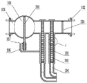
Fig. 1 is a schematic structural view of the present invention.
Fig. 2 is a left side view of fig. 1.
Fig. 3 is a sectional view taken along line a-a in fig. 1.
Fig. 4 is a sectional view taken along line B-B in fig. 1.
Fig. 5 is an enlarged view of a portion C in fig. 4.
Detailed Description
The following describes embodiments of the present invention in detail with reference to the drawings, which are implemented on the premise of the technical solution of the present invention, and detailed embodiments and specific operation procedures are provided, but the scope of the present invention is not limited to the following embodiments.
As shown in figures 1-5, the self-cleaning valve for the inlet water of the storage tank comprises a shell, a flow control assembly and a self-cleaning assembly. Specifically, be provided with the chamber 101 that overflows that is used for into water in the casing 1, overflow chamber 101 both ends welding and have the ring flange 102 that is used for connecting the regulation pond inlet tube, and the middle part intercommunication has the filter chamber 103 that is used for the scrubbing, and above-mentioned filter chamber 103 is one at least (two in this embodiment), and its axis all is located the chamber 101 outside that overflows (the radius of filter chamber 103 is greater than the diameter of overflowing chamber 101 promptly), and the bottom of each filter chamber 103 all communicates a sewage pipes 104.
The flow control assembly is located at the inlet end of the flow-through chamber 101, and comprises a gate valve blade 201 installed in the flow-through chamber 101 and a control runner 202 located outside the housing 1, and the opening degree of the gate valve blade 201 can be adjusted by the control runner 202, so as to control the water flow in the flow-through chamber 101. The periphery of the gate valve blade 201 is wrapped with a soft rubber sealing ring.
The self-cleaning assembly comprises a follower rotary vane 301 positioned at the outlet end of the flow-through cavity 101, a filter screen plate 302 positioned in the filter cavity 103, and a transmission mechanism connecting the two. The diameter of the follower rotary vane 301 is generally larger than that of the gate valve blade 201, and therefore, the housing 1 where the follower rotary vane 301 is located has a spherical structure (see fig. 1). The central axis of the follower rotary vane 301 is provided with a radial rotary shaft 303 perpendicular to the flow direction of water in the flow passage cavity 101, and the radial rotary shaft 303 is rotatably connected with the shell 1 and extends out of the shell. When the storage tank is filled with water, the follow-up rotating blades 301 rotate in the circumferential direction under the action of inflow water, so that the radial rotating shafts 303 rotate in the same direction.
The two filter screen plates 302 are respectively installed in the two filter cavities 103 and are concentrically arranged with the filter cavities 103, the centers of the two filter screen plates 302 are fixedly connected with the same horizontal rotating shaft 304, and one end of the horizontal rotating shaft 304 extending to the outside of the shell 1 is arranged close to the radial rotating shaft 303.
An L-shaped support frame 305 is welded on the shell 1 below the horizontal rotating shaft 304, a transmission shaft 306 is installed between the vertical plate of the support frame and the outer wall of the shell 1, and the transmission shaft 306 is parallel to the horizontal rotating shaft 304. The radial rotating shaft 303 is provided with a worm 307 (i.e. a first connecting end of the transmission mechanism), the transmission shaft 306 is provided with a worm wheel 308, the horizontal rotating shaft 304 is provided with a reduction gear 309 (i.e. a second connecting end of the transmission mechanism), and the worm wheel 308 is meshed with the worm 307 and the reduction gear 309 respectively.
When the radial rotating shaft 303 rotates, the worm 307, the turbine 308 and the reduction gear 309 are linked to drive the filter screen plate 302 to rotate, so that each part of the filter screen plate 302 can alternately filter the inflow water flow, the filtering effect is improved, and a part of the inflow water flow can flow downwards along a gap between the shell 1 and the filter screen plate 302 to wash and clean the filter screen plate 302, and then the part of the inflow water flow and impurities are discharged through the sewage discharge pipeline 104. Because the number of teeth of the reduction gear 309 is greater than that of the worm gear 308, the rotating speed of the filter screen plate 302 can be indirectly reduced, and the influence on the flow of the inflow water flow caused by the over-fast rotation of the filter screen plate 302 is avoided.
Further, in order to enhance the cleaning effect of the filter screen plate 302, the inner wall of the housing 1 at the position of the filter cavity 103 is provided with the impurity scraping knife 4, and the cutting edge of the impurity scraping knife 4 is arranged downward and facing the coming direction of the filter screen plate 302, so that the impurities scraped by the impurity scraping knife 4 are ensured to fall downward and not to be deposited on the impurity scraping knife 4. In general, the impurity scraping knives 4 are arranged in pairs, and each pair of impurity scraping knives 4 are symmetrically arranged on two sides of the filter screen plate 302; secondly, install transparent observation window 5 on the casing 1 of filter chamber 103 department, can observe whether filter screen 302 normally operates, conveniently overhauls at any time.
It should be noted that in the description of the present invention, terms of orientation or positional relationship such as "front", "rear", "left", "right", "vertical", "horizontal", "inner", "outer", etc., are based on the orientation or positional relationship shown in the drawings, and are only for convenience of description and simplification of description, but do not indicate or imply that the device or element referred to must have a specific orientation, be constructed and operated in a specific orientation, and thus, should not be construed as limiting the present invention.
Claims (10)
1. The utility model provides a regulation pond is with automatically cleaning valve of intaking which characterized in that: comprises that
The sewage treatment device comprises a shell, a sewage treatment device and a sewage treatment device, wherein the shell is provided with an overflowing cavity for water inflow, the middle part of the overflowing cavity is communicated with a filtering cavity for removing sewage, and the central axis of the filtering cavity is arranged on the outer side of the overflowing cavity;
the flow control assembly is arranged at the inlet end of the overflowing cavity;
self-cleaning assembly comprising
The follow-up rotating blade is arranged at the outlet end of the overflowing cavity and is provided with a radial rotating shaft which is vertical to the overflowing cavity, and the radial rotating shaft penetrates out of the shell;
the filter screen plate is arranged in the filter cavity, a horizontal rotating shaft is arranged at the center of the filter screen plate, and the horizontal rotating shaft penetrates out of the shell;
and the transmission mechanism is provided with a first connecting end connected with the radial rotating shaft and a second connecting end connected with the horizontal rotating shaft.
2. The influent self-cleaning valve for a storage tank of claim 1, wherein: the end of the overflowing cavity is provided with a flange plate used for connecting a water inlet pipe of the storage tank.
3. The influent self-cleaning valve for a storage tank of claim 1, wherein: the overflowing cavity is at least one, and the bottom of each overflowing cavity is communicated with a sewage discharge pipeline.
4. The influent self-cleaning valve for a storage tank of claim 1, wherein: the flow control assembly comprises a gate valve blade arranged in the overflowing cavity and a control rotating wheel arranged outside the shell.
5. The influent self-cleaning valve for a storage tank of claim 4, wherein: the diameter of the follow-up rotating blade is larger than that of the gate valve blade, and the shell where the follow-up rotating blade is located is of a spherical structure.
6. The influent self-cleaning valve for a storage tank of claim 1, wherein: and an observation window is arranged on the outer wall of the filter cavity.
7. The influent self-cleaning valve for a storage tank of claim 1, wherein: and the inner wall of the filter cavity is provided with a trash scraping knife, and the cutting edge of the trash scraping knife is arranged downwards and faces the coming direction of the filter screen plate.
8. The influent self-cleaning valve for a storage tank of claim 7, wherein: the impurity scraping knives are arranged in pairs, and each pair of the impurity scraping knives is symmetrically arranged on two sides of the filter screen plate.
9. The influent self-cleaning valve for a storage tank of claim 1, wherein: the transmission mechanism comprises a transmission shaft arranged in parallel with the horizontal rotating shaft, a turbine is arranged on the transmission shaft, and the turbine is respectively meshed with a reduction gear arranged on the horizontal rotating shaft and a worm arranged on the radial rotating shaft.
10. The influent self-cleaning valve for a storage tank of claim 9, wherein: the shell is provided with an L-shaped support frame used for connecting the transmission shaft and the radial rotating shaft.
Priority Applications (1)
| Application Number | Priority Date | Filing Date | Title |
|---|---|---|---|
| CN202122267120.6U CN215842011U (en) | 2021-09-18 | 2021-09-18 | Water inlet self-cleaning valve for storage tank |
Applications Claiming Priority (1)
| Application Number | Priority Date | Filing Date | Title |
|---|---|---|---|
| CN202122267120.6U CN215842011U (en) | 2021-09-18 | 2021-09-18 | Water inlet self-cleaning valve for storage tank |
Publications (1)
| Publication Number | Publication Date |
|---|---|
| CN215842011U true CN215842011U (en) | 2022-02-18 |
Family
ID=80254704
Family Applications (1)
| Application Number | Title | Priority Date | Filing Date |
|---|---|---|---|
| CN202122267120.6U Active CN215842011U (en) | 2021-09-18 | 2021-09-18 | Water inlet self-cleaning valve for storage tank |
Country Status (1)
| Country | Link |
|---|---|
| CN (1) | CN215842011U (en) |
Cited By (1)
| Publication number | Priority date | Publication date | Assignee | Title |
|---|---|---|---|---|
| CN115977219A (en) * | 2023-01-30 | 2023-04-18 | 北京首创生态环保集团股份有限公司 | Automatic water supply and drainage device |
-
2021
- 2021-09-18 CN CN202122267120.6U patent/CN215842011U/en active Active
Cited By (1)
| Publication number | Priority date | Publication date | Assignee | Title |
|---|---|---|---|---|
| CN115977219A (en) * | 2023-01-30 | 2023-04-18 | 北京首创生态环保集团股份有限公司 | Automatic water supply and drainage device |
Similar Documents
| Publication | Publication Date | Title |
|---|---|---|
| CN112707539B (en) | Intelligent sewage filtering device and control method | |
| CN220791613U (en) | Anti-blocking sewage pump | |
| CN213743991U (en) | Leading anti-blocking device of sewage pipeline | |
| CN208123074U (en) | A kind of cities and towns water conservancy and hydropower priming device | |
| CN217188289U (en) | BAF sewage advanced treatment equipment | |
| CN115105878A (en) | Anti-leakage valve | |
| CN213477103U (en) | Integrated intelligent sewage intercepting well | |
| CN213868183U (en) | Can prevent municipal rainwater entry structure of jam | |
| CN204723838U (en) | A kind of secondary filter with Automatic clearance function | |
| CN218843280U (en) | Production drain pipe capable of avoiding blockage | |
| CN218814208U (en) | Drainage diverging device for water supply and drainage engineering | |
| CN220918279U (en) | Valve for hydraulic engineering | |
| CN208815647U (en) | A kind of water pipeline for hydraulic engineering | |
| CN115467280B (en) | Water conservancy construction water conservancy diversion drainage structures | |
| CN217430907U (en) | Novel rainwater sewage reposition of redundant personnel device | |
| CN214784367U (en) | Rainwater collection device for municipal works | |
| CN210767170U (en) | Prefabricated pump station of hand-free basket and sewage treatment system | |
| CN208965676U (en) | A kind of anti-blocking drain pipe road system | |
| CN222457792U (en) | Sewage pump anti-blocking device | |
| CN216972153U (en) | Water supply and drainage device for industrial sewage treatment | |
| CN214219897U (en) | A new type of drainage pipe | |
| CN220185467U (en) | A submersible pump with anti-blocking function | |
| CN223082359U (en) | A kind of engineering drainage filtration and treatment equipment | |
| CN220815951U (en) | Anti-blocking drainage device suitable for water conservancy | |
| CN221287149U (en) | Interception device for sewage treatment |
Legal Events
| Date | Code | Title | Description |
|---|---|---|---|
| GR01 | Patent grant | ||
| GR01 | Patent grant |