Four-roller calender
Technical Field
The utility model relates to the field of four-roller calenders, in particular to a four-roller calender.
Background
The four-roller calender is a calender with four rollers, the arrangement forms of the rollers are T-shaped, L-shaped, S-shaped, Z-shaped and the like, and the four-roller calender has the characteristics of high efficiency, high precision and the like. The rubber is mainly used for rubberizing of fabrics, rubberizing of wirecord fabrics, pressing of sizing materials, rubber blank profiling, isolation rubber sheet rubberizing, multilayer rubber sheet rubberizing and the like in the rubber industry. The Z-shaped rollers are reasonably arranged, so that the elastic deformation of the rollers can be reduced, the feeding is facilitated, and the application is wider.
At present, most of four-roller calenders can adhere to certain colloid residues on the outer wall surface of a roller after the film is extruded on a textile fabric or a steel cord fabric, and can seriously affect the secondary practicability of the calender if the adhesive residues are not cleaned in time.
SUMMERY OF THE UTILITY MODEL
The present invention aims to provide a four-roll calender to solve the problems set forth in the background art.
In order to achieve the purpose, the utility model provides the following technical scheme: four-roller calender, including the calender, the inboard middle part of calender rotates and is connected with four rollers, the collecting vat of collecting clean waste material is installed to the inboard bottom of calender, the top middle part fixedly connected with link of calender, the top middle part of link is provided with the basin of storage clear water or cleaning solution, the below of basin is provided with the induction pipe, water or cleaning solution in the basin lead in to cleaning device through the induction pipe, and wash below roller outer wall through cleaning device, cleaning device's rear middle part is provided with and drives cleaning device the latter half pivoted and rotate the wheel.
Preferably, the middle parts of the left side and the right side of the roller are rotationally connected with the left inner wall and the right inner wall of the calender through shafts, and the roller is distributed in an L shape in the calender.
Preferably, the middle part of the upper part of the calender is provided with a connecting frame, the middle parts of the lower part of the connecting frame and the upper part of the calender are communicated with each other, and the middle part of the connecting frame is provided with a cleaning device.
Preferably, cleaning device includes fixing base, gear, bulb, fan, rolling disc and gondola water faucet, and cleaning device passes through the top middle part inner wall fixed connection of fixing base and link.
Preferably, the ball groove is formed in the outer side of the lower portion of the fixing seat, the ball head is connected to the outer side of the lower portion of the fixing seat in a sliding mode, the lower portion of the ball head is fixedly connected with the upper surface of the gear, the gear is rotatably connected with the fixing seat through the ball head, and the fan is fixedly connected to the lower surface of the gear.
Preferably, the lower part of the fan is fixedly connected with the upper surface of the rotating disc through a connecting rod, the lower part of the rotating disc is fixedly connected with an inclined block, and the shower head is fixedly connected with the rotating disc in an inclined mode through the inclined block.
Preferably, the middle parts of the fixed seat, the gear, the fan and the rotating disc are provided with through holes, the guide-in pipe vertically penetrates through the through holes and is rotatably connected with the through holes, the lower end of the guide-in pipe is communicated with the shower head, and the upper end of the guide-in pipe is communicated with the water tank.
Preferably, the middle part of the rear side of the cleaning device is rotatably connected with a rotating wheel, the rotating wheel is rotatably connected with the gear and meshed with the gear, and the middle part above the rotating wheel is rotatably connected with the motor through a shaft.
Compared with the prior art, the utility model has the beneficial effects that: according to the cleaning device, the cleaning device is added, so that the colloid residue on the outer wall of the roller can be effectively cleaned, the adverse effect on the subsequent use of the roller is prevented, the cleaning solution is more uniformly sprayed on the roller by the inclined shower head, the cleaning solution is more tightly contacted with the roller by the fan, and the cleaning solution can be conveniently discharged out of the colloid residue on the roller.
Drawings
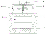
FIG. 1 is a front view of the present invention;
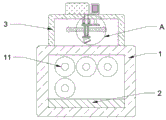
FIG. 2 is a side view of the present invention;
FIG. 3 is a view showing the structure at A in FIG. 2 according to the present invention.
In the figure: calender 1, roller 11, collecting vat 2, link 3, basin 4, induction pipe 41, cleaning device 5, fixing base 51, gear 52, bulb 53, fan 54, rolling disc 55, gondola water faucet 56, running wheel 6.
Detailed Description
The technical solutions in the embodiments of the present invention will be clearly and completely described below with reference to the drawings in the embodiments of the present invention, and it is obvious that the described embodiments are only a part of the embodiments of the present invention, and not all of the embodiments. All other embodiments, which can be derived by a person skilled in the art from the embodiments given herein without making any creative effort, shall fall within the protection scope of the present invention.
Referring to fig. 1 to 3, the present invention provides a technical solution: four roller calenders, including calender 1, the inboard middle part of calender 1 rotates and is connected with four rollers 11, and the collecting vat 2 of collecting clean waste material is installed to the inboard bottom of calender 1.
The upper middle part of calender 1 is fixedly connected with link 3, and the upper middle part of link 3 is provided with basin 4 of storage clear water or cleaning solution.
An introduction pipe 41 is provided below the water tank 4, and water or cleaning liquid in the water tank 4 is introduced into the cleaning device 5 through the introduction pipe 41, and the outer wall of the lower roller 11 is cleaned by the cleaning device 5.
The middle parts of the left side and the right side of the roller 11 are rotationally connected with the left inner wall and the right inner wall of the calender 1 through shafts, and the roller 11 is distributed in an L shape inside the calender 1.
The top middle part of calender 1 is provided with link 3, and the below of link 3 and the top middle part of calender 1 UNICOM each other, and the mid-mounting of link 3 has cleaning device 5.
Cleaning device 5 includes fixing base 51, gear 52, bulb 53, fan 54, rolling disc 55 and gondola water faucet 56, and cleaning device 5 passes through fixing base 51 and the upper middle part inner wall fixed connection of link 3.
The ball groove is formed in the outer side of the lower portion of the fixed seat 51, the ball head 53 is connected in the ball groove in a sliding mode, the lower portion of the ball head 53 is fixedly connected with the upper surface of the gear 52, the gear 52 is rotatably connected with the fixed seat 51 through the ball head 53, and the fan 54 is fixedly connected to the lower surface of the gear 52.
The lower part of the fan 54 is fixedly connected with the upper surface of the rotating disc 55 through a connecting rod, the lower part of the rotating disc 55 is fixedly connected with an inclined block, and the shower head 56 is fixedly connected with the rotating disc 55 in an inclined mode through the inclined block.
The fixed seat 51, the gear 52, the fan 54 and the rotating disc 55 are all provided with through holes at the middle part, the inlet pipe 41 vertically passes through the through holes and is rotatably connected with the through holes, the lower end of the inlet pipe 41 is communicated with the shower head 56, and the upper end of the inlet pipe 41 is communicated with the water tank 4.
The middle part of the rear part of the cleaning device 5 is provided with a rotating wheel 6 which drives the lower half part of the cleaning device 5 to rotate.
The middle part of the rear side of the cleaning device 5 is rotatably connected with a rotating wheel 6, the rotating wheel 6 is rotatably connected with a gear 52 and mutually meshed, and the middle part above the rotating wheel 6 is rotatably connected with a motor through a shaft.
The working principle is as follows: after the film is extruded onto the fabric or wire cord fabric by the roller 11 inside the calender 1, the glue remains on the outer wall of the roller 11.
The motor is started to drive the rotating wheel 6 to rotate through the shaft, and the rotating wheel 6 and the gear 52 are meshed with each other, so that the gear 52 is driven to rotate along with the rotation of the rotating wheel 6.
The upper part of the gear 52 is rotationally connected with the fixed seat 51 through the structure of the ball head 53 and the ball groove, and the lower part of the gear 52 is fixedly connected with the top part of the fan 54.
That is, with the rotation of gear 52, fan 54 is rotated to blow air onto roll 11 while holding holder 51 stationary.
And the lower part of the fan 54 is fixedly connected with the rotating disc 55 through the connecting rod, so that the fan 54 drives the rotating disc 55 to rotate, and the shower head 56 rotates.
Since the shower head 56 is obliquely fixed under the rotary plate 55, when the cleaning liquid in the water tank 4 flows into the shower head 56 through the introduction pipe 41, the cleaning liquid inside is uniformly sprinkled on the drum 11 as the shower head 56 rotates.
And the cleaning liquid on the roller 11 is accelerated to slide down by the blowing action of the fan 54, and the colloid residue on the roller 11 is driven to slide down.
Colloid residue and cleaning solution get into collecting vat 2 after coming off from roller 11, conveniently carry out recovery processing to it.
Although embodiments of the present invention have been shown and described, it will be appreciated by those skilled in the art that changes, modifications, substitutions and alterations can be made in these embodiments without departing from the principles and spirit of the utility model, the scope of which is defined in the appended claims and their equivalents.