CN215825000U - Burr removing device for aluminum alloy door and window - Google Patents
Burr removing device for aluminum alloy door and window Download PDFInfo
- Publication number
- CN215825000U CN215825000U CN202121868734.3U CN202121868734U CN215825000U CN 215825000 U CN215825000 U CN 215825000U CN 202121868734 U CN202121868734 U CN 202121868734U CN 215825000 U CN215825000 U CN 215825000U
- Authority
- CN
- China
- Prior art keywords
- lifting
- upper side
- motor
- sweeps
- section bar
- Prior art date
- Legal status (The legal status is an assumption and is not a legal conclusion. Google has not performed a legal analysis and makes no representation as to the accuracy of the status listed.)
- Expired - Fee Related
Links
- 229910000838 Al alloy Inorganic materials 0.000 title claims abstract description 20
- 229910001651 emery Inorganic materials 0.000 claims abstract description 8
- 239000000428 dust Substances 0.000 abstract description 5
- 239000002699 waste material Substances 0.000 description 11
- 238000004519 manufacturing process Methods 0.000 description 5
- 238000000034 method Methods 0.000 description 4
- 230000000694 effects Effects 0.000 description 3
- 230000000903 blocking effect Effects 0.000 description 2
- 239000000463 material Substances 0.000 description 2
- 230000004888 barrier function Effects 0.000 description 1
- 230000009286 beneficial effect Effects 0.000 description 1
Images

Landscapes
- Finish Polishing, Edge Sharpening, And Grinding By Specific Grinding Devices (AREA)
Abstract
The utility model discloses a deburring device for aluminum alloy doors and windows, which comprises a base, wherein movable guide rails are respectively installed at two ends of the upper side of the base, a rack is installed between the two movable guide rails on the upper side of the base, a sliding plate is installed on the upper side of a sliding block, a supporting column and a movable motor are installed on the upper side of the sliding plate, a gear is meshed with the rack, a lifting motor is installed on the upper side of the supporting column, a rotating motor is installed on one side of the front end of a lifting arm, an output shaft of the rotating motor penetrates through the lifting arm to be connected with a working frame, a grinding wheel motor is installed on the upper side of the working frame, a grinding wheel is installed on the output shaft of the grinding wheel motor, a cutter is fixedly connected to the bottom end of a cutter fixing frame through screws, and fixing devices are symmetrically installed at two ends of the upper side of a scrap collecting box. Can fix the section bar, need not the operator and fix the section bar with the hand, the cutter cuts the section bar, and the emery wheel carries out the abrasive dust burring to the section bar that cuts, and the rubber pad avoids L type fixed block, fixed plate and section bar to produce the friction and leaves the mar on the section bar.
Description
Technical Field
The utility model relates to the technical field of aluminum alloy door and window processing, in particular to a deburring device for aluminum alloy doors and windows.
Background
In the production and processing process of the aluminum alloy doors and windows, the section bars for manufacturing the aluminum alloy doors and windows need to be cut, burrs are easily left in cutting openings of the cut section bars, and if the burrs are not ground and removed, hands of production workers are easily scratched, and the production quality of the aluminum alloy doors and windows is influenced.
In the process of production and processing, the aluminum alloy section bar is cut firstly, then burrs are removed from the cut abrasive dust of the section bar, two-person operation is needed when the aluminum alloy section bar is cut or the burrs are removed, one person is responsible for fixing, the other person is responsible for cutting or the burrs are removed, the cutting or the abrasive dust is low in efficiency, the safety coefficient is low, and a large amount of manpower and material resources are wasted.
Disclosure of Invention
The utility model aims to provide a deburring device for an aluminum alloy door and window, which can fix a section without fixing the section by hands of an operator, cut the section by a cutter, grind and deburr the cut section by a grinding wheel, greatly reduce the labor intensity of workers, protect the aluminum alloy door and window by arranging a rubber pad, and avoid scratches on the section due to friction of an L-shaped fixing block, a fixing plate and the section.
The technical scheme adopted by the utility model for solving the technical problems is as follows: a deburring device for aluminum alloy doors and windows comprises a base, wherein moving guide rails are respectively installed at two ends of the upper side of the base, a rack is installed between the two moving guide rails on the upper side of the base, a sliding block is installed on the upper side of each moving guide rail, a sliding plate is installed on the upper side of each sliding block, a supporting column and a moving motor are installed on the upper side of each sliding plate, a gear is installed on an output shaft at the lower end of each moving motor and is meshed with the rack, a lifting motor is installed on the upper side of each supporting column, lifting guide rails are installed at the left and right ends of the front side of each supporting column, a lifting sliding block is installed on each lifting guide rail, a lifting sliding plate is installed on each lifting sliding block, a lead screw is installed between the two lifting guide rails, each lifting motor is connected with the lead screw, a nut seat is screwed on the outer side wall of the lead screw and is connected with the rear side of each lifting sliding plate, a lifting arm is installed on the front side of each lifting arm, a rotating motor is installed on one side of the front end of each lifting arm, an output shaft of each rotating motor penetrates through each lifting arm and is connected with a working frame, the grinding wheel motor is installed to the workstation upside, installs the emery wheel on the output shaft of grinding wheel motor, and the pneumatic cylinder is installed to workstation one side upper end, and pneumatic cylinder bottom fixedly connected with hydraulic stem, the cutter mount is installed to the hydraulic stem lower extreme, and screw fixedly connected with cutter is passed through to cutter mount bottom, and the base front side is connected with the sweeps and collects the box, and the sweeps is collected box upside both ends symmetry and is installed fixing device.
Further, fixing device includes L type fixed block, die clamping cylinder and fixed plate, and the box upside both ends symmetry L type fixed block is collected to the sweeps, and die clamping cylinder is installed to L type fixed block upper end inboard, installs the fixed plate on the die clamping cylinder.
Furthermore, rubber pads are arranged on the opposite sides of the L-shaped fixing blocks and the fixing plate.
Furthermore, the two sides of the upper end of the waste chip collecting box are provided with the stop plates, the bottom of the inner side of the waste chip collecting box is provided with a waste chip collecting drawer, and the outer side of the waste chip collecting drawer is provided with a handle.
The utility model has the following beneficial effects: the profile can be fixed without an operator fixing the profile by hands, the profile is cut by the cutter, and the cut profile is subjected to abrasive dust deburring by the grinding wheel, so that the labor intensity of workers is greatly reduced;
the rubber pad that one side that L type fixed block and fixed plate are relative set up, play protection aluminum alloy door and window's effect, avoid L type fixed block, the fixed plate produces the friction with the section bar and leaves the mar on the section bar, the setting of rotating electrical machines, can overturn the work frame and realize the switching between emery wheel motor and the pneumatic cylinder, the sweeps is collected box and sweeps and is collected the collection sweeps that setting up of drawer can be timely, the effect that the sweeps splashes can be prevented to the barrier plate of box upside is collected to the sweeps.
Drawings
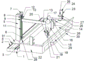
FIG. 1 is a schematic view of the overall structure of the present invention;
fig. 2 is a schematic view of the structure of the rack gear of fig. 1.
Wherein: 1. the automatic grinding machine comprises a base, 2, a movable guide rail, 3, a rack, 4, a sliding block, 5, a supporting column, 6, a movable motor, 7, a lifting motor, 8, a lifting guide rail, 9, a lifting sliding block, 10, a lifting sliding plate, 11, a screw rod, 12, a nut seat, 13, a lifting arm, 14, a rotating motor, 15, a working frame, 16, a grinding wheel motor, 17, a grinding wheel, 18, a hydraulic cylinder, 19, a hydraulic rod, 20, a tool fixing frame, 21, a tool, 22, a waste chip collecting box, 23, a fixing device, 24, an L-shaped fixing block, 25, a clamping cylinder, 26, a fixing plate, 27, a rubber pad, 28, a blocking plate, 29, a waste chip collecting drawer, 30, a handle, 31 and a sliding plate.
Detailed Description
The present invention will now be described in further detail with reference to the accompanying drawings.
As shown in fig. 1 and 2, the deburring device for the aluminum alloy doors and windows is characterized in that: the lifting device comprises a base 1, movable guide rails 2 are respectively installed at two ends of the upper side of the base 1, a rack 3 is installed between the two movable guide rails 2 on the upper side of the base 1, a sliding block 4 is installed on the upper side of each movable guide rail 2, a sliding plate 31 is installed on the upper side of the sliding block 4, a supporting column 5 and a movable motor 6 are installed on the upper side of the sliding plate 31, a gear is installed on an output shaft at the lower end of the movable motor 6, the gear is meshed with the rack 3, a lifting motor 7 is installed on the upper side of the supporting column 5, lifting guide rails 8 are installed at the left and right ends of the front side of the supporting column 5, a lifting sliding block 9 is installed on the lifting guide rails 8, a lifting sliding plate 10 is installed on the lifting sliding block 9, a lead screw 11 is installed between the two lifting guide rails 8, the lifting motor 7 is connected with the lead screw 11, a nut seat 12 is screwed on the outer side wall of the lead screw 11, the nut seat 12 is connected with the rear side of the lifting sliding plate 10, a lifting arm 13 is installed on the front side, a rotating motor 14 is installed on one side of the lifting arm 13, the output shaft of rotating electrical machines 14 passes lifing arm 13 and is connected with work frame 15, emery wheel motor 16 is installed to 15 upsides of work frame, install emery wheel 17 on emery wheel motor 16's the output shaft, pneumatic cylinder 18 is installed to 15 one side upper ends of work frame, 18 bottom fixedly connected with hydraulic stem 19 of pneumatic cylinder, cutter mount 20 is installed to 19 lower extremes of hydraulic stem, screw fixedly connected with cutter 21 is passed through to cutter mount 20 bottom, 1 front side of base is connected with the sweeps and collects box 22, 22 upside both ends symmetry are collected to the sweeps and fixing device 23 is installed.
The fixing device 23 comprises an L-shaped fixing block 24, a clamping cylinder 25 and a fixing plate 26, the L-shaped fixing block 24 is symmetrically arranged at two ends of the upper side of the waste collecting box 22, the clamping cylinder 25 is arranged on the inner side of the upper end of the L-shaped fixing block 24, and the fixing plate 26 is arranged on the clamping cylinder 25.
And rubber pads 27 are arranged on the opposite sides of the L-shaped fixing block 24 and the fixing plate 26.
A blocking plate 28 is installed on each of two sides of the upper end of the waste chip collecting box 22, a waste chip collecting drawer 29 is arranged at the bottom of the inner side of the waste chip collecting box 22, and a handle 30 is installed on the outer side of the waste chip collecting drawer 29.
When in use, firstly, the height of the fixing plate 26 is adjusted through the clamping cylinder 25, the aluminum alloy door and window is firmly fixed by the fixing plate 26 and the L-shaped fixing block 24, the rubber pad 27 arranged at one side of the L-shaped fixing block 24 opposite to the fixing plate 26 plays a role in protecting the sectional material and avoiding the L-shaped fixing block 24, fixed plate 26 produces the friction with the section bar and leaves the mar on the section bar, the back-and-forth movement of mobile motor 6 control support column 5 and lifing arm 13, the work that reciprocates of lifing arm 13 is controlled to elevator motor 7, rotating electrical machines 14 control work frame 15 overturns to 180, pneumatic cylinder 18 control cutter cuts the section bar, grinding wheel motor 16 control emery wheel 17 carries out the abrasive dust burring to the section bar that cuts, the collection sweeps that setting up of box 22 and sweeps collection drawer 29 can be timely is collected to the sweeps, the effect that the sweeps splashes everywhere can be prevented to the baffle plate 28 of box 22 upside is collected to the sweeps.
The present invention is not limited to the above embodiments, and any structural changes made under the teaching of the present invention shall fall within the scope of the present invention, which is similar or similar to the technical solutions of the present invention.
The techniques, shapes, and configurations not described in detail in the present invention are all known techniques.
Claims (4)
1. The utility model provides an aluminum alloy door and window burring device which characterized in that: comprises a base, wherein both ends of the upper side of the base are respectively provided with a movable guide rail, a rack is arranged between the two movable guide rails on the upper side of the base, the upper side of each movable guide rail is provided with a slide block, the upper side of each slide block is provided with a support column and a movable motor, the output shaft at the lower end of the movable motor is provided with a gear which is meshed with the rack, the upper side of each support column is provided with a lifting motor, the left end and the right end of the front side of each support column are provided with a lifting guide rail, each lifting guide rail is provided with a lifting slide block, each lifting slide block is provided with a lifting slide plate, a lead screw is arranged between the two lifting guide rails, the lifting motor is connected with the lead screw, the outer side wall of the lead screw is screwed with a nut seat, the nut seat is connected with the rear side of the lifting slide plate, the front side of each lifting slide plate is provided with a lifting arm, one side of the front end of each lifting arm is provided with a rotating motor, the output shaft of the rotating motor passes through the lifting arm and is connected with a working frame, the grinding wheel motor is installed to the workstation upside, installs the emery wheel on the output shaft of grinding wheel motor, and the pneumatic cylinder is installed to workstation one side upper end, and pneumatic cylinder bottom fixedly connected with hydraulic stem, the cutter mount is installed to the hydraulic stem lower extreme, and screw fixedly connected with cutter is passed through to cutter mount bottom, and the base front side is connected with the sweeps and collects the box, and the sweeps is collected box upside both ends symmetry and is installed fixing device.
2. The deburring device for aluminum alloy doors and windows according to claim 1, characterized in that: fixing device includes L type fixed block, die clamping cylinder and fixed plate, and the box upside both ends symmetry L type fixed block is collected to the sweeps, and die clamping cylinder is installed to L type fixed block upper end inboard, installs the fixed plate on the die clamping cylinder.
3. The deburring device for aluminum alloy doors and windows according to claim 2, characterized in that: and rubber pads are arranged on the opposite sides of the L-shaped fixed block and the fixed plate.
4. The deburring device for aluminum alloy doors and windows according to claim 1, characterized in that: the baffle is all installed to sweeps collection box upper end both sides, and the sweeps is collected box inboard bottom and is equipped with the sweeps and collects the drawer, and the handle is installed in the sweeps collection drawer outside.
Priority Applications (1)
| Application Number | Priority Date | Filing Date | Title |
|---|---|---|---|
| CN202121868734.3U CN215825000U (en) | 2021-08-11 | 2021-08-11 | Burr removing device for aluminum alloy door and window |
Applications Claiming Priority (1)
| Application Number | Priority Date | Filing Date | Title |
|---|---|---|---|
| CN202121868734.3U CN215825000U (en) | 2021-08-11 | 2021-08-11 | Burr removing device for aluminum alloy door and window |
Publications (1)
| Publication Number | Publication Date |
|---|---|
| CN215825000U true CN215825000U (en) | 2022-02-15 |
Family
ID=80194586
Family Applications (1)
| Application Number | Title | Priority Date | Filing Date |
|---|---|---|---|
| CN202121868734.3U Expired - Fee Related CN215825000U (en) | 2021-08-11 | 2021-08-11 | Burr removing device for aluminum alloy door and window |
Country Status (1)
| Country | Link |
|---|---|
| CN (1) | CN215825000U (en) |
-
2021
- 2021-08-11 CN CN202121868734.3U patent/CN215825000U/en not_active Expired - Fee Related
Similar Documents
| Publication | Publication Date | Title |
|---|---|---|
| CN213004411U (en) | Grinding device for casting machining | |
| CN211276710U (en) | Cutting device for machine tool | |
| CN113414591B (en) | Portable machine tool for machining | |
| CN219617271U (en) | Planer-type milling machine capable of automatically cleaning scrap iron | |
| CN214134219U (en) | Automobile fastener cutting device | |
| CN215280139U (en) | Vertical profile sawing equipment | |
| CN217193000U (en) | Novel section bar cutting machine | |
| CN215145346U (en) | A cutting device for automobile shock absorber processing | |
| CN216227286U (en) | Numerical control sawing machine capable of controlling cutting length for machining guide sleeve | |
| CN213969203U (en) | Milling machine with protective structure | |
| CN213397881U (en) | Safe and reliable type spectrum sample grinding machine | |
| CN211306568U (en) | Automatic pay-off circular sawing machine | |
| CN223441786U (en) | A centre gripping platform keeps off bits water conservancy diversion structure for digit control machine tool | |
| CN209754695U (en) | Milling machine garbage collection device is used in mould steel processing | |
| CN207915109U (en) | A kind of Metal Cutting Machine Tool that can prevent metal fillings from splashing | |
| CN224011354U (en) | Protective and safe sawing machine for metal processing | |
| CN216729745U (en) | Key gear milling machine for automobile lock and motorcycle lock | |
| CN223301257U (en) | A CNC sawing and milling machine for multi-directional processing | |
| CN222471724U (en) | Machine tool structure with collection function | |
| CN213560286U (en) | Suspension type metal band sawing machine | |
| CN221159585U (en) | Turning and milling composite numerical control machine tool with inclined lathe bed | |
| CN213970243U (en) | Cutter for preventing scraps from splashing | |
| CN211279176U (en) | Edge cutting machine | |
| CN220863414U (en) | Rim charge removing mechanism for pin shaft machining | |
| CN214693887U (en) | Protective device |
Legal Events
| Date | Code | Title | Description |
|---|---|---|---|
| GR01 | Patent grant | ||
| GR01 | Patent grant | ||
| CF01 | Termination of patent right due to non-payment of annual fee | ||
| CF01 | Termination of patent right due to non-payment of annual fee |
Granted publication date: 20220215 |