CN215824158U - High-voltage cable feeding device - Google Patents
High-voltage cable feeding device Download PDFInfo
- Publication number
- CN215824158U CN215824158U CN202123364821.8U CN202123364821U CN215824158U CN 215824158 U CN215824158 U CN 215824158U CN 202123364821 U CN202123364821 U CN 202123364821U CN 215824158 U CN215824158 U CN 215824158U
- Authority
- CN
- China
- Prior art keywords
- shaped frame
- roller
- voltage cable
- base
- push
- Prior art date
- Legal status (The legal status is an assumption and is not a legal conclusion. Google has not performed a legal analysis and makes no representation as to the accuracy of the status listed.)
- Active
Links
Images


Abstract
The utility model discloses a high-voltage cable feeding device which comprises a base, wherein universal wheels are arranged at the bottom of the base, a push-pull rod is arranged at one side end of the base, supporting plates which are oppositely arranged are respectively arranged on the base close to one end provided with the push-pull rod and close to two sides of the end, a winding roller is rotatably arranged on the supporting plates, an inverted U-shaped frame is arranged on one side, far away from the side provided with the push-pull rod, of the supporting plates on the base, and a cable feeding mechanism is arranged on the U-shaped frame. The utility model has the advantages that: the device is arranged in a movable mode, so that the device is more flexible in use, the design is reasonable, the structure is simple, the maintenance is convenient, the rotating roller driven by the motor and the extruding roller matched with the rotating roller are arranged, the high-voltage cable can be mechanically conveyed without manpower traction, the working efficiency is improved, the working strength of workers is reduced, and the anti-slip pads are arranged on the rotating roller and the extruding roller, so that the stability in conveying the high-voltage cable can be ensured.
Description
Technical Field
The utility model relates to the technical field of electric power facilities, in particular to a high-voltage cable feeding device.
Background
For the big square cable of high pressure, because its square number is big, weight is great, can not rotate voluntarily because of the traction force of machine equipment at the in-process of setting off the production line, often need can accomplish with the help of external force, and two people cooperate, alone stretch out the electric wire at the front end, alone cooperate and cut off, but this kind of way, consuming time and power to, manual operation, the wearing and tearing that also may increase the wire rod are unfavorable for the cable construction. With the rapid development of modern technology, high-efficiency production has become a necessity and social consensus. Various devices are developing towards the characteristics of reducing labor intensity, improving process stability and working efficiency, improving product quality and the like. The automatic wire feeding device has important significance in solving the problems of automatic wire feeding and the like of the cables, particularly high-voltage large-square cables.
SUMMERY OF THE UTILITY MODEL
The technical problem to be solved by the utility model is to provide a high-voltage cable feeding device which is reasonable in design and convenient to use.
In order to solve the technical problems, the technical scheme provided by the utility model is as follows: the high-voltage cable feeding device comprises a base, universal wheels are arranged at the bottom of the base, a push-pull rod is arranged at one side end of the base, supporting plates which are oppositely arranged are respectively arranged at one end, close to the two sides, of the base, close to the end, provided with the push-pull rod, of the supporting plate, a winding roller is arranged on the supporting plate in a rotating mode, an inverted U-shaped frame is arranged at one side, far away from the side, provided with the push-pull rod, of the supporting plate on the base, and a cable feeding mechanism is arranged on the U-shaped frame.
As an improvement, the wire feeding mechanism comprises a rotating roller arranged on a U-shaped frame, a squeezing roller is arranged on the U-shaped frame in a sliding mode above the rotating roller, a motor A is arranged on the U-shaped frame, and a transmission shaft of the motor A penetrates through the U-shaped frame and is connected with a rotating shaft of the rotating roller.
As an improvement, a through groove is formed in one side, provided with a motor A, of the U-shaped frame, mounting plates are respectively arranged at the upper side end and the lower side end, close to the through groove, of the U-shaped frame, guide rods and lead screws are respectively arranged on the two sides of the through groove between the mounting plates, sliding blocks are arranged on the guide rods and the lead screws in a penetrating mode, rotating shafts of the extrusion rollers are arranged on the sliding blocks in a rotating mode in a penetrating mode through the through groove, the top ends of the lead screws are connected with the bevel gear A in a penetrating mode, a motor B is arranged on the mounting plates, and transmission shafts of the motor B are connected with the bevel gear B meshed with the bevel gear A.
As an improvement, the supporting plate is provided with a placing groove, and the placing groove is obliquely and downwards arranged from the top end of one side, close to the push-pull rod, of the supporting plate.
As an improvement, the diameter of the rotating roller is gradually reduced from two ends to the middle, the diameter of the extrusion roller is gradually increased from two ends to the middle, and the extrusion roller and the rotating roller are arranged in a matched mode.
As an improvement, the squeezing roller and the rotating roller are provided with anti-slip pads.
Compared with the prior art, the utility model has the advantages that: the device is arranged in a movable mode, so that the device is more flexible in use, the design is reasonable, the structure is simple, the maintenance is convenient, the rotating roller driven by the motor and the extruding roller matched with the rotating roller are arranged, the high-voltage cable can be mechanically conveyed without manpower traction, the working efficiency is improved, the working strength of workers is reduced, and the anti-slip pads are arranged on the rotating roller and the extruding roller, so that the stability in conveying the high-voltage cable can be ensured.
Drawings
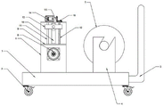
Fig. 1 is a schematic structural diagram of a high-voltage cable feeding device according to the present invention.
Fig. 2 is a schematic structural diagram of a wire feeding mechanism of a high-voltage cable feeding device according to the present invention.
Fig. 3 is a schematic structural diagram of a support plate of a high-voltage cable feeding device according to the present invention.
As shown in the figure: 1. a base; 2. a universal wheel; 3. a push-pull rod; 4. a support plate; 5. a winding roll; 6. a U-shaped frame; 7. a placement groove; 8. a motor A; 9. mounting a plate; 10. a through groove; 11. a guide bar; 12. a screw rod; 13. a slider; 14. a motor B; 15. a bevel gear B; 16. a bevel gear A; 17. a squeeze roll; 18. the roller is rotated.
Detailed Description
The present invention will be described in further detail with reference to the accompanying drawings.
With reference to the accompanying drawings 1-3, the high-voltage cable feeding device comprises a base 1, universal wheels 2 are arranged at the bottom of the base 1, a push-pull rod 3 is arranged at the end of one side of the base 1, supporting plates 4 which are arranged oppositely are arranged on the base 1 close to the end provided with the push-pull rod 3 and close to the two sides of the end, a winding roller 5 is arranged on the supporting plates 4 in a rotating mode, an inverted U-shaped frame 6 is arranged on the base 1 on the side, far away from the side provided with the push-pull rod 3, of the supporting plates 4, and a cable feeding mechanism is arranged on the U-shaped frame 6.
The wire feeding mechanism comprises a rotating roller 18 arranged on a U-shaped frame 6, a squeezing roller 17 is arranged on the U-shaped frame 6 in a sliding mode above the rotating roller 18, a motor A8 is arranged on the U-shaped frame 6, and a transmission shaft of a motor A8 penetrates through the U-shaped frame 6 and is connected with a rotating shaft of the rotating roller 18.
The automatic packaging machine is characterized in that a through groove 10 is formed in one side, provided with a motor A8, of the U-shaped frame 6, mounting plates 9 are respectively arranged at the upper side end and the lower side end, close to the through groove 10, of the U-shaped frame 6, guide rods 11 and lead screws 12 are respectively arranged on two sides of the through groove 10 between the mounting plates 9, sliding blocks 13 are arranged on the guide rods 11 and the lead screws 12 in a penetrating mode, a rotating shaft of a squeezing roller 17 penetrates through the through groove 10 and is rotatably arranged on the sliding blocks 13, the top end of each lead screw 12 penetrates through the mounting plate 9 and is connected with a bevel gear A16, a motor B14 is arranged on the mounting plate 9, and a transmission shaft of the motor B14 is connected with a bevel gear B15 meshed with the bevel gear A16.
The supporting plate 4 is provided with a placing groove 7, and the placing groove 7 is obliquely and downwards arranged from the top end of one side, close to the push-pull rod 3, of the supporting plate 4.
The diameter of the rotating roller 18 is gradually reduced from two ends to the middle, the diameter of the squeezing roller 17 is gradually increased from two ends to the middle, and the squeezing roller 17 and the rotating roller 18 are arranged in a matched mode.
And anti-slip pads are arranged on the squeezing roller 17 and the rotating roller 18.
The working principle of the utility model is as follows: when using, will hang in the standing groove in the backup pad around the spiral roller that is equipped with the high-pressure cable, pull the cable and place on the live-rollers, starter motor B, make it drive bevel gear B and rotate, thereby drive bevel gear A and rotate, make the lead screw rotate then, the slider realizes descending along with the rotation of lead screw, make the squeeze roll move down and closely laminate with the cable, starter motor A, make it drive the live-rollers rotation, thereby it removes to drive the cable, make the cable carry, the slipmat can increase frictional force, guarantee that the cable carries steadily.
The present invention and its embodiments have been described above, and the description is not intended to be limiting, and the drawings are only one embodiment of the present invention, and the actual structure is not limited thereto. In summary, those skilled in the art should appreciate that they can readily use the disclosed conception and specific embodiments as a basis for designing or modifying other structures for carrying out the same purposes of the present invention without departing from the spirit and scope of the utility model as defined by the appended claims.
Claims (6)
1. The utility model provides a high-voltage cable pay-off, includes base (1), its characterized in that: the wire winding machine is characterized in that universal wheels (2) are arranged at the bottom of the base (1), a push-pull rod (3) is arranged at the end part of one side of the base (1), supporting plates (4) which are arranged oppositely are arranged at the end, close to the end provided with the push-pull rod (3), of the base (1) respectively on the two sides, a wire winding roller (5) is arranged on the supporting plates (4) in a rotating mode, an inverted U-shaped frame (6) is arranged on one side, far away from the side provided with the push-pull rod (3), of the supporting plates (4) on the base (1), and a wire feeding mechanism is arranged on the U-shaped frame (6).
2. A high voltage cable routing device as claimed in claim 1, wherein: the wire feeding mechanism comprises a rotating roller (18) arranged on a U-shaped frame (6), a squeezing roller (17) is arranged on the U-shaped frame (6) in a sliding mode above the rotating roller (18), a motor A (8) is arranged on the U-shaped frame (6), and a transmission shaft of the motor A (8) penetrates through the U-shaped frame (6) and is connected with a rotating shaft of the rotating roller (18).
3. A high voltage cable routing device as claimed in claim 2, wherein: the automatic feeding device is characterized in that a through groove (10) is formed in one side, provided with a motor A (8), of the U-shaped frame (6), mounting plates (9) are arranged on the upper side end and the lower side end, close to the through groove (10), of the U-shaped frame (6), guide rods (11) and lead screws (12) are arranged on the two sides of the through groove (10) between the mounting plates (9), sliding blocks (13) penetrate through the guide rods (11) and the lead screws (12), a rotating shaft of an extrusion roller (17) penetrates through the through groove (10) to be rotatably arranged on the sliding blocks (13), the top end of each lead screw (12) penetrates through the mounting plate (9) to be connected with a bevel gear A (16), a motor B (14) is arranged on the mounting plate (9), and a transmission shaft of the motor B (14) is connected with a bevel gear B (15) meshed with the bevel gear A (16).
4. A high voltage cable routing device as claimed in claim 1, wherein: the supporting plate (4) is provided with a placing groove (7), and the placing groove (7) is obliquely and downwards arranged from the top end of one side, close to the push-pull rod (3), of the supporting plate (4).
5. A high voltage cable routing device as claimed in claim 2, wherein: the diameter of the rotating roller (18) is gradually reduced from two ends to the middle, the diameter of the squeezing roller (17) is gradually increased from two ends to the middle, and the squeezing roller (17) is matched with the rotating roller (18).
6. A high voltage cable routing device as claimed in claim 2, wherein: and anti-slip pads are arranged on the squeezing roller (17) and the rotating roller (18).
Priority Applications (1)
| Application Number | Priority Date | Filing Date | Title |
|---|---|---|---|
| CN202123364821.8U CN215824158U (en) | 2021-12-30 | 2021-12-30 | High-voltage cable feeding device |
Applications Claiming Priority (1)
| Application Number | Priority Date | Filing Date | Title |
|---|---|---|---|
| CN202123364821.8U CN215824158U (en) | 2021-12-30 | 2021-12-30 | High-voltage cable feeding device |
Publications (1)
| Publication Number | Publication Date |
|---|---|
| CN215824158U true CN215824158U (en) | 2022-02-15 |
Family
ID=80202977
Family Applications (1)
| Application Number | Title | Priority Date | Filing Date |
|---|---|---|---|
| CN202123364821.8U Active CN215824158U (en) | 2021-12-30 | 2021-12-30 | High-voltage cable feeding device |
Country Status (1)
| Country | Link |
|---|---|
| CN (1) | CN215824158U (en) |
-
2021
- 2021-12-30 CN CN202123364821.8U patent/CN215824158U/en active Active
Similar Documents
| Publication | Publication Date | Title |
|---|---|---|
| CN208166204U (en) | A kind of cable processing wrapping machine | |
| CN109019141B (en) | Optical fiber hoisting and laying device | |
| CN104960985A (en) | Cable recovering device | |
| CN112124393A (en) | Moving stator conveying device and conveying method | |
| CN215824158U (en) | High-voltage cable feeding device | |
| CN110993211A (en) | Cable stripping equipment to power cable retrieves | |
| CN207397816U (en) | A kind of cable recycling separate type wire stripper | |
| CN207312845U (en) | A kind of anti-skid power cable cable reel | |
| CN108711475A (en) | A kind of core feed mechanism for conducting wire poling | |
| CN209871953U (en) | Uniform winding device for cables | |
| CN204778030U (en) | Cable conductor tensioning rolling equipment | |
| CN206840199U (en) | Sponge cutting equipment | |
| CN216657240U (en) | Unloader on large-scale sheet metal component | |
| CN115938788A (en) | Iron core winding device for transformer production and processing | |
| CN110000260A (en) | A kind of profile lateral bending furling plate round machine | |
| CN214359444U (en) | Wire and cable pay-off device | |
| CN213816729U (en) | Multifunctional wire stripping machine for insulated cables | |
| CN210941124U (en) | Embossing equipment for metal plate | |
| CN204777999U (en) | Cable conductor recovery plant | |
| CN110137865A (en) | A kind of cable drum cutter device | |
| CN107244558A (en) | A kind of ceramic panel turnover machine of Novel foaming | |
| CN204792237U (en) | Cable conductor rolling equipment of flare -outing | |
| CN207691332U (en) | Wire stripper | |
| CN206327986U (en) | A kind of telpher | |
| CN216509369U (en) | Semi-automatic wheat of wrapping up in is drawn device |
Legal Events
| Date | Code | Title | Description |
|---|---|---|---|
| GR01 | Patent grant | ||
| GR01 | Patent grant |