Transformer power generation cooling structure
Technical Field
The utility model relates to a power generation cooling structure of a transformer, and belongs to the technical field of transformer manufacturing.
Background
The power transformer is one of the most complex and most core electrical devices in the structure of the power system. With the improvement of voltage grade and transformation capacity, the cooling technology of the transformer is mature. The prior art power generation mainly depends on thermal power generation, namely, power generation by fuel such as coal and the like. Thermal power generation generates a large amount of carbon dioxide, which is harmful to a large amount. Today advocating energy saving and emission reduction, too much carbon dioxide can accelerate global warming, accelerate the thawing of the glaciers of the two poles of the world, the national territory at low altitude in the coast can shrink, the habitability area of human beings can be reduced, and the global climate change can be influenced at the same time, so that drought and flood disasters are frequent. Under the condition, the energy conservation and emission reduction inevitably raises the national agenda, reduces the carbon emission, and changes the economic development mode, thereby not only representing the development level of the national advanced productivity, but also representing the national force level of a country. Therefore, it has become necessary to reduce the amount of electricity used for ignition. The chinese utility model patent CN2017210153657 discloses a novel transformer for heat dissipation photovoltaic power generation, which immerses a thermoelectric generation piece in transformer oil, the other side of the thermoelectric generation piece is connected with solar energy light gathering, the cold surface of the thermoelectric generation piece contacts the transformer oil, the hot surface is connected with the light gathering part, the structure is unreasonable and not easy to realize, the transformer is difficult to install during the manufacture, the manufacturing cost is high, and the existing space of the transformer is not fully utilized; in addition, for a large-scale power transformer, transformer oil is cooled by forced circulation, a transformer cooler of the transformer also needs to consume a part of electric energy, and how to fully utilize space and waste heat of the transformer to generate electricity and use the electricity and the heat to be used for cooling the large-scale power transformer is a technical problem to be solved in the field.
SUMMERY OF THE UTILITY MODEL
The utility model aims to provide a transformer power generation cooling structure, which fully utilizes the space and waste heat of a transformer to generate power and is used for cooling a large-scale power transformer, is organically combined with the manufacturing and application of the transformer, is easy to realize, reduces the cost, assists in solar power generation, reduces the power consumption of thermal power generation, is green and environment-friendly, and solves the problems in the background art.
The technical scheme of the utility model is as follows:
a power generation cooling structure of a transformer comprises a transformer oil tank, an uninterrupted power supply, a transformer cooler and a transformer power generation system, wherein the transformer oil tank is connected with the transformer cooler, and the transformer cooler is used for forcibly circulating and cooling transformer oil in the transformer oil tank; the top of the transformer oil tank is provided with a transformer power generation system which is connected with an uninterruptible power supply, and the uninterruptible power supply is connected with a transformer cooler; the transformer power generation system comprises cold and hot temperature difference power generation pieces, photovoltaic panels, a first inverter and a second inverter, wherein the cold and hot temperature difference power generation pieces are arranged in a manner of being clung to a transformer oil tank and absorbing surface heat of the transformer oil tank to generate power; the first inverter and the second inverter are both connected with the uninterruptible power supply.
The top of the transformer oil tank is vertically provided with a plurality of support plates, the cold and hot temperature difference power generation pieces are located among the support plates, the partition plates are perpendicular to the support plates and are arranged above the cold and hot temperature difference power generation pieces, the first inverter and the second inverter are located on the partition plates, the top of each support plate is provided with a top plate, the top plates are located above the first inverter and the second inverter, and the photovoltaic panels are installed on the top plates.
A first wire protection tube is arranged between each of the first inverter and the second inverter and the uninterruptible power supply, and a first power transmission wire is positioned in the first wire protection tube; and a second wire protection tube is arranged between the uninterruptible power supply and the transformer cooler, and the second electricity transmission wire is positioned in the second wire protection tube.
The support plate is fastened with two ends of the top of the transformer oil tank through connecting bolts; the support plate and the partition plate, and the support plate and the top plate are connected together in a welding manner; the photovoltaic panel is arranged on the top plate; the cold and hot thermoelectric generation piece is tightly attached to the transformer oil tank below the partition plate.
The transformer oil tank and the top of the transformer cooler are provided with supports, the photovoltaic panels are arranged on the supports, the number of the photovoltaic panels is enough, and the photovoltaic panels and the cold and hot temperature difference power generation sheets supply power to the transformer cooler together, so that the forced circulation cooling requirement of transformer oil is met.
The solar energy power generation system is characterized in that a cold and hot temperature difference power generation piece is used for generating power by utilizing the difference between the internal oil temperature of a transformer oil tank and the external environment temperature, solar power generation is carried out by utilizing the transformer oil tank and a photovoltaic panel on the top of a transformer cooler, and the generated energy of the two parts is supplied to the transformer cooler through an uninterruptible power supply to carry out forced circulation cooling on transformer oil.
The utility model fully utilizes the waste heat and space of the transformer, and has practical application effect on supporting the green environmental protection idea advocated by the state.
One surface of the cold and hot temperature difference power generation sheet is in contact with the top of the transformer oil tank (the actual temperature of the top of the transformer oil tank is basically consistent with the temperature of transformer oil), one surface of the cold and hot temperature difference power generation sheet is in contact with air, because the temperature of the air is lower than the temperature of the transformer oil, the power generation is actually carried out by utilizing the temperature difference between the high temperature of the transformer oil and the environment, meanwhile, the solar power generation and the cold and hot power generation of the transformer oil are parallel, and the space at the top of the transformer is fully utilized.
The utility model has the beneficial effects that: the space and the waste heat of the transformer are fully utilized for power generation and used for cooling of the large-scale power transformer, the cooling device is organically combined with the manufacturing and application of the transformer, the implementation is easy, the cost is reduced, the solar power generation is assisted, the power consumption of thermal power generation is reduced, and the cooling device is green and environment-friendly.
Drawings
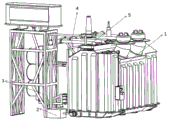
FIG. 1 is a schematic diagram of the overall structure of an embodiment of the present invention;
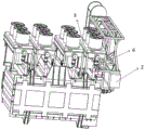
FIG. 2 is a bottom schematic view of an embodiment of the present invention;
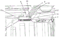
FIG. 3 is a schematic structural diagram of a power generation system on the top of a transformer oil tank according to an embodiment of the utility model;
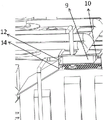
FIG. 4 is a partial schematic view of a power generation system at the top of a transformer tank according to an embodiment of the present invention;
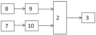
FIG. 5 is a schematic diagram of an embodiment of the present invention;
in the figure: the device comprises a transformer oil tank 1, an uninterruptible power supply 2, a transformer cooler 3, a first lead protection pipe 4, a transformer power generation system 5, a second lead protection pipe 6, a cold and hot thermoelectric generation piece 7, a photovoltaic panel 8, a first inverter 9, a second inverter 10, a partition plate 11, a support plate 12, a top plate 13 and a connecting bolt 14.
Detailed Description
The utility model is further illustrated by the following examples in conjunction with the accompanying drawings.
A power generation cooling structure of a transformer comprises a transformer oil tank 1, an uninterruptible power supply 2, a transformer cooler 3 and a transformer power generation system 5, wherein the transformer oil tank 1 is connected with the transformer cooler 3, and the transformer cooler 3 is used for forcibly circulating and cooling transformer oil in the transformer oil tank 1; the top of the transformer oil tank 1 is provided with a transformer power generation system 5, the transformer power generation system 5 is connected with an uninterruptible power supply 2, and the uninterruptible power supply 2 is connected with a transformer cooler 3; the transformer power generation system 5 comprises a cold and hot temperature difference power generation sheet 7, photovoltaic panels 8, a first inverter 9 and a second inverter 10, wherein the cold and hot temperature difference power generation sheets 7 are arranged in a manner of being clung to the transformer oil tank 1 and absorbing surface heat of the transformer oil tank 1 to generate power, the cold and hot temperature difference power generation sheets 7 are connected in series with each other and connected with the second inverter together, the photovoltaic panels 8 are arranged at the top of the transformer, and the photovoltaic panels are connected in series with each other and connected with the second inverter together; the first inverter and the second inverter are both connected with the uninterruptible power supply.
The top of the transformer oil tank 1 is vertically provided with a plurality of support plates 12, the cold and hot thermoelectric generation piece 7 is located among the support plates 12, the partition plate 11 is perpendicular to the support plates 12 and is arranged above the cold and hot thermoelectric generation piece 7, the first inverter 9 and the second inverter 10 are located on the partition plate 11, the top of the support plates 12 is provided with a top plate 13, the top plate 13 is located above the first inverter 9 and the second inverter 10, and the photovoltaic plate 8 is installed on the top plate 13.
A first lead protection tube 4 is arranged between the first inverter 9 and the second inverter 10 and the uninterruptible power supply 2, and a first power transmission lead is positioned in the first lead protection tube 4; and a second wire protection tube 6 is arranged between the uninterruptible power supply 2 and the transformer cooler 3, and the second electricity transmission wire is positioned in the second wire protection tube 6.
The support plate 12 is fastened with two ends of the top of the transformer oil tank 1 through connecting bolts; the support plate and the partition plate, and the support plate and the top plate are connected together in a welding manner; the photovoltaic panel is arranged on the top plate; the cold and hot thermoelectric generation piece is tightly attached to the transformer oil tank 1 below the partition plate.
The transformer oil tank 1 and the transformer cooler 3 are provided with supports at the tops, the photovoltaic panels 8 are arranged on the supports, the photovoltaic panels 8 are enough in number and supply power to the transformer cooler 3 together with the cold and hot temperature difference power generation sheets 7, and the requirement of forced circulation cooling of transformer oil is met.
The difference between the internal oil temperature of the transformer oil tank and the external environment temperature is utilized to generate electricity by adopting the cold-hot temperature difference power generation sheet 7, the solar energy power generation is carried out by utilizing the transformer oil tank 1 and the photovoltaic panel at the top of the transformer cooler 3, and the generated energy of the two parts is supplied to the transformer cooler 3 through the uninterrupted power supply 2 to carry out forced circulation cooling on the transformer oil.
The utility model fully utilizes the waste heat and space of the transformer, and has practical application effect on supporting the green environmental protection idea advocated by the state.
One surface of the cold and hot temperature difference power generation sheet is in contact with the top of the transformer oil tank (the actual temperature of the top of the transformer oil tank is basically consistent with the temperature of transformer oil), one surface of the cold and hot temperature difference power generation sheet is in contact with air, because the temperature of the air is lower than the temperature of the transformer oil, the power generation is actually carried out by utilizing the temperature difference between the high temperature of the transformer oil and the environment, meanwhile, the solar power generation and the cold and hot power generation of the transformer oil are parallel, and the space at the top of the transformer is fully utilized.
The transformer oil tank is connected with the transformer cooler through bolts; the transformer power generation system comprises a support plate, a partition plate, a top plate, a cold and hot temperature difference power generation sheet, a photovoltaic plate, a first inverter, a second inverter and a first power transmission lead. A support plate of the transformer power generation system is fixed with two ends of the top of the transformer oil tank through connecting bolts; the support plate and the partition plate, and the support plate and the top plate are connected together in a welding manner; utilize the difference of the inside oil temperature of transformer tank and external environment temperature to generate electricity with cold and hot thermoelectric generation piece, utilize the photovoltaic board at transformer tank 1 and the 3 tops of transformer cooler to carry out solar energy power generation, the generated energy of two parts is supplied with transformer cooler 3 through uninterrupted power source 2 and is cooled the transformer oil forced circulation, make full use of the waste heat and the space of transformer, played practical application effect to the green theory of advocating to the support country.