Curtain is decorated to aluminium veneer
Technical Field
The utility model relates to the technical field of aluminum veneers, in particular to an aluminum veneer decorative curtain wall.
Background
The aluminum veneer is divided into three types from surface treatment, namely polyester powder spraying, polyester paint spraying and fluorocarbon paint spraying, the aluminum veneer curtain wall is formed by processing a pure aluminum plate, the aluminum veneer curtain wall is a novel decorative material, various colors can be sprayed on the surface of the aluminum veneer curtain wall, and the aluminum veneer curtain wall has the characteristics of high strength, low cost, long service life and the like.
Current aluminium veneer curtain passes through the bolt fastening on keel frame one by one with the aluminum plate unit mostly when the installation, because aluminum plate unit quantity is huge, and the installation process is very hard consuming time, and efficiency is lower, increases the cost of manpower and materials. Accordingly, one skilled in the art provides an aluminum veneer decorative curtain wall to solve the above problems in the background art.
SUMMERY OF THE UTILITY MODEL
The utility model aims to provide an aluminum veneer decorative curtain wall to solve the problems in the background technology.
In order to achieve the purpose, the utility model provides the following technical scheme:
the utility model provides a curtain is decorated to aluminium veneer, includes horizontal fossil fragments, indulges fossil fragments and lock post, horizontal fossil fragments bottom is provided with indulges fossil fragments, horizontal fossil fragments comprise first pair of lamella buckle, it comprises second pair of lamella buckle to indulge fossil fragments, first pair of lamella buckle with second pair of lamella buckle inside all be provided with the installation catching groove lock post and buckle closure.
As a still further scheme of the utility model: indulge the fossil fragments with cross keel welded fastening and inside intercommunication, first pair of lamella buckle with second pair of lamella buckle is aluminum alloy material and makes, first pair of lamella buckle with second pair of lamella buckle welding, the installation catching groove is seted up in first pair of lamella buckle with on a lateral wall of second pair of lamella buckle.
As a still further scheme of the utility model: the lock cylinder is welded with the inner walls of the first pair of petal buckling plates and the second pair of petal buckling plates, the first pair of petal buckling plates and the second pair of petal buckling plates are internally and rightly welded with buckling caps on one side wall of the lock cylinder, and the buckling caps are matched with the lock cylinder for insertion.
As a still further scheme of the utility model: a combined bolt column is welded at one corner inside the first pair of petal-shaped buckle plates, and bolt holes are formed in the second pair of petal-shaped buckle plates at the top ends of the combined bolt columns in a penetrating mode.
As a still further scheme of the utility model: the utility model discloses a keel structure, including horizontal fossil fragments, indulge fossil fragments back wall, horizontal fossil fragments with it has the installation pin all to weld on the fossil fragments back wall, horizontal fossil fragments with it has individual layer aluminum plate to indulge the card pressure between the fossil fragments, there is the aluminum alloy angle sign indicating number through the bolt fastening on the individual layer aluminum plate outside wall, set up angle sign indicating number hole on the aluminum alloy angle sign indicating number.
As a still further scheme of the utility model: the aluminum alloy angle sign indicating number with the installation catching groove aligns the installation, the angle sign indicating number hole with the lock post cooperation is pegged graft, be fixed with the strengthening rib on the inside wall of individual layer aluminum plate, the strengthening rib with it has aluminium matter rivet to run through between the individual layer aluminum plate.
Compared with the prior art, the utility model has the beneficial effects that:
according to the utility model, the traditional aluminum veneer curtain wall fixing frame is designed into the buckling type mounting keel frame consisting of the transverse keel, the longitudinal keel, the first pair of lamella buckling plates, the second pair of lamella buckling plates, the locking columns and the buckling caps, so that the aluminum plate units can be uniformly and quickly buckled into the keel frame, and then the keel frame is buckled and screwed with a small number of screws, thereby not only ensuring the stable clamping of the aluminum plate units, but also greatly shortening the mounting time, improving the working efficiency and saving the manpower and material resources cost.
Drawings
FIG. 1 is a schematic structural view of the present invention;
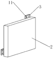
FIG. 2 is a schematic structural view of a single-layer aluminum plate according to the present invention;
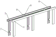
fig. 3 is a schematic view of the internal structure of the transverse keel and the longitudinal keel of the utility model;
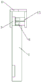
FIG. 4 is a schematic view showing the connection relationship between the single-layer aluminum plate and the cross keel according to the present invention;
FIG. 5 is a top sectional view of a single-layer aluminum sheet according to the present invention.
In the figure: 1-transverse keel; 2-single layer aluminum plate; 3-aluminum alloy corner connectors; 4-bolt holes; 5-assembling bolt columns; 6-a first pair of petal buckle plates; 7-a second pair of gusset plates; 8-locking the column; 9-installing a buckle slot; 10-longitudinal keel; 11-corner code holes; 12-mounting pins; 13-buckling a cap; 14-reinforcing ribs; 15-aluminum rivet.
Detailed Description
The technical solutions in the embodiments of the present invention will be clearly and completely described below with reference to the drawings in the embodiments of the present invention, and it is obvious that the described embodiments are only a part of the embodiments of the present invention, and not all of the embodiments. All other embodiments, which can be derived by a person skilled in the art from the embodiments given herein without making any creative effort, shall fall within the protection scope of the present invention.
Referring to fig. 1 to 5, in the embodiment of the present invention, the keel comprises a cross keel 1, a longitudinal keel 10 and a lock column 8, the bottom of the cross keel 1 is provided with the longitudinal keel 10, the cross keel 1 is composed of a first pair of lamella buckling plates 6, the longitudinal keel 10 is composed of a second pair of lamella buckling plates 7, and the first pair of lamella buckling plates 6 and the second pair of lamella buckling plates 7 are both internally provided with an installation buckling groove 9, a lock column 8 and a buckling cap 13.
The longitudinal keel 10 is fixedly welded with the cross keel 1 and is internally communicated, the first pair of petal buckling plates 6 and the second pair of petal buckling plates 7 are both made of aluminum alloy materials, the first pair of petal buckling plates 6 and the second pair of petal buckling plates 7 are welded, the installation buckling grooves 9 are formed in one side wall of the first pair of petal buckling plates 6 and the second pair of petal buckling plates 7, the first pair of petal buckling plates 6 and the second pair of petal buckling plates 7 are both of a two-petal clamping structure, in the specific construction process, an integral structure or a separated unit structure of the cross keel 1 and the main keel can be selected according to the size of a wall surface, and the units are fixed through temporary welding; the lock column 8, the first pair of petal buckle plates 6 and the second pair of petal buckle plates 7 are welded and formed, a buckle cap 13 is welded on one side wall, opposite to the lock column 8, in the first pair of petal buckle plates 6 and the second pair of petal buckle plates 7, the buckle cap 13 is matched and spliced with the lock column 8, and the buckle cap 13 is used for clamping the single-layer aluminum plate 2 on the lock column 8 to avoid shaking; a combined bolt column 5 is welded at one corner inside the first pair of petal buckle plates 6, bolt holes 4 are formed in the second pair of petal buckle plates 7 at the top ends of the combined bolt columns 5 in a penetrating mode, two groups of combined bolt columns 5 are located on the upper wall and the lower wall of the first pair of petal buckle plates 6 and the second pair of petal buckle plates 7 respectively and are connected and communicated through screws in a screwed mode; mounting pins 12 are welded on the back walls of the transverse keel 1 and the longitudinal keel 10, a single-layer aluminum plate 2 is clamped between the transverse keel 1 and the longitudinal keel 10, an aluminum alloy corner connector 3 is fixed on the outer wall of the single-layer aluminum plate 2 through a bolt, a corner connector 11 is formed in the aluminum alloy corner connector 3, the aluminum alloy corner connector 3 is used for mounting and fixing the single-layer aluminum plate 2, and the position of the aluminum alloy corner connector is adjustable; the aluminum alloy angle sign indicating number 3 aligns the installation with installation catching groove 9, and angle sign indicating number hole 11 is pegged graft with the cooperation of lock post 8, is fixed with strengthening rib 14 on the inside wall of individual layer aluminum plate 2, and it has aluminium matter rivet 15 to run through between strengthening rib 14 and the individual layer aluminum plate 2.
The working principle of the utility model is as follows: when the device is installed specifically, a first pair of petal buckling plates 6 on a cross keel 1 and a second pair of petal buckling plates 7 on a longitudinal keel 10 are separated, half of the first pair of petal buckling plates 6 and the second pair of petal buckling plates 7 are installed on a wall surface through installation pins 12, then a single-layer aluminum plate 2 is clamped into an installation buckling groove 9 through an aluminum alloy corner connector 3, a corner connector 11 on the aluminum alloy corner connector 3 is inserted into a locking column 8, so that the single-layer aluminum plate 2 can be stably fixed between the first pair of petal buckling plates 6 and the second pair of petal buckling plates 7, after the single-layer aluminum plate 2 of the whole wall surface is installed, the other half of the first pair of petal buckling plates 6 and the second pair of petal buckling plates 7 are installed in an aligned mode, a bolt hole 4 is aligned with a combined bolt column 5, a buckling cap 13 is aligned with the locking column 8, and after the first pair of petal buckling plates 6 and the second pair of petal buckling plates 7 are buckled, a screw can be screwed in the bolt hole 4, compress tightly fixedly with it, to the further compressing tightly of individual layer aluminum plate 2, avoid taking place to rock, compare in the huge aluminum plate unit of traditional quantity screw installation mode one by one, the appearance of this design can be so that the aluminum plate unit is unified to be detained into keel frame fast, get up keel frame lock again and connect the less screw of quantity soon, both ensure to the firm clamp of aluminum plate unit tightly, reduced the time of installation again greatly, improved work efficiency, practiced thrift manpower and materials cost.
The above description is only for the preferred embodiment of the present invention, but the scope of the present invention is not limited thereto, and any person skilled in the art should be considered to be within the technical scope of the present invention, and equivalent alternatives or modifications according to the technical solution of the present invention and the inventive concept thereof should be covered by the scope of the present invention.