Split charging equipment for disinfectant
Technical Field
The utility model belongs to the technical field of disinfectant, and particularly relates to split charging equipment for disinfectant.
Background
The disinfectant is commonly used for sterilizing articles in living environment or production environment, has become one of the types of commonly used cleaning agents at present due to convenient use, strong sterilization capability and high action speed, is more and more popular with users, and when the conventional disinfectant is subpackaged and produced, the solution is easy to spill when the liquid adding head is filled due to the overlarge distance between the liquid adding head and a container bottle, so that the problems of inconvenient use and low subpackaging efficiency exist.
SUMMERY OF THE UTILITY MODEL
To solve the problems set forth in the background art described above. The utility model provides split charging equipment for disinfectant, wherein the limiting frames arranged at the two sides of the conveying belt can improve the stability of container bottles moving on the conveying belt, the height of a liquid adding head can be adaptively adjusted according to the height and the size of the container bottles, the precision during filling is improved, and the split charging equipment has the characteristics of high filling efficiency and convenience in operation and use.
In order to achieve the purpose, the utility model provides the following technical scheme: a split charging device for disinfectant comprises a conveying frame, roller shafts are rotatably arranged at two ends of the conveying frame, the two roller shafts are in transmission connection through a conveying belt, and a first motor for driving the roll shaft to rotate is fixedly arranged at one end of the conveying frame, a plurality of supporting plates are arranged in a matching way with the conveying belt, sleeves for positioning the containers to be subpackaged are fixedly arranged at the upper parts of the supporting plates, limiting frames for supporting plates are arranged at the two side edges of the conveying belt, a liquid supply device is arranged above the conveying belt, the liquid supply device comprises a liquid storage tank which is fixedly arranged above the conveying frame, a liquid inlet is arranged at the upper part of the liquid storage tank, a liquid outlet is arranged at the lower part of the liquid storage tank, the liquid outlet is connected with a liquid adding head through a hose, and a driving mechanism for controlling the lifting of the liquid adding head is arranged on the liquid storage tank, the upper part of the conveying belt is also provided with a blocking mechanism for fixing the position of the supporting plate during the split charging of the disinfectant.
Preferably, the limiting frame is of an L-shaped structure, the bottom edge of the limiting frame is fixedly connected with the conveying frame, and a limiting groove for the side edge of the supporting plate to penetrate through is formed between the limiting frame and the conveying belt.
Preferably, actuating mechanism includes second motor, first gear, second gear, lead screw, thread bush and U type frame, U type frame fixed mounting is in the lower part of liquid storage pot, the thread bush passes through the bearing and rotates and install on U type frame, the lead screw is connected and the bottom and the first fixed connection of liquid feeding of lead screw with thread bush screw thread transmission, second motor fixed mounting is on the liquid storage pot, first gear fixed mounting is on the output shaft of second motor, second gear fixed mounting is on the thread bush, and first gear and second gear meshing transmission are connected.
Preferably, the blocking mechanism comprises an air cylinder and a stop block, the cylinder end of the air cylinder is fixedly installed above the conveying belt, and the stop block is fixedly installed at the telescopic end of the bottom of the air cylinder.
Compared with the prior art, the utility model has the beneficial effects that:
according to the sub-packaging device, the limiting frames arranged on the two sides of the conveying belt can improve the stability of the container bottles when the container bottles move on the conveying belt, the height of the liquid adding head can be adaptively adjusted according to the height and the size of the container bottles, the accuracy of filling is improved, and the sub-packaging device has the advantages of being high in filling efficiency and convenient to operate and use.
Drawings
The accompanying drawings, which are included to provide a further understanding of the utility model and are incorporated in and constitute a part of this specification, illustrate embodiments of the utility model and together with the description serve to explain the principles of the utility model and not to limit the utility model. In the drawings:
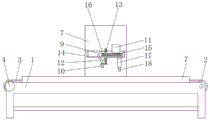
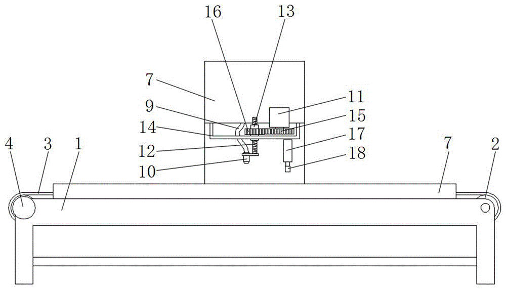
FIG. 1 is a schematic structural view of the present invention;
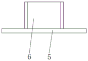
FIG. 2 is a schematic structural view of a support plate and a sleeve;
in the figure: the automatic feeding device comprises a conveying frame 1, a roller shaft 2, a conveying belt 3, a first motor 4, a supporting plate 5, a sleeve 6, a limiting frame 7, a liquid storage tank 8, a hose 9, a liquid adding head 10, a second motor 11, a screw rod 12, a thread bush 13, a U-shaped frame 14, a first gear 15, a second gear 16, an air cylinder 17 and a stop dog 18.
Detailed Description
The technical solutions in the embodiments of the present invention will be clearly and completely described below with reference to the drawings in the embodiments of the present invention, and it is obvious that the described embodiments are only a part of the embodiments of the present invention, and not all of the embodiments. All other embodiments, which can be derived by a person skilled in the art from the embodiments given herein without making any creative effort, shall fall within the protection scope of the present invention.
Examples
Referring to fig. 1-2, the present embodiment provides the following technical solutions: a split charging device for disinfectant comprises a conveying frame 1, wherein roll shafts 2 are rotatably arranged at two ends of the conveying frame 1, the two roll shafts 2 are in transmission connection through a conveying belt 3, a first motor 4 used for driving the roll shafts 2 to rotate is fixedly arranged at one end of the conveying frame 1, a plurality of supporting plates 5 are arranged in a matching manner with the conveying belt 3, sleeves 6 used for positioning containers to be split charged are fixedly arranged at the upper parts of the supporting plates 5, limiting frames 7 used for the supporting plates 5 are arranged at two side edges of the conveying belt 3, the limiting frames 7 are of an L-shaped structure, the bottom edges of the limiting frames 7 are fixedly connected with the conveying frame 1, a limiting groove for the side edges of the supporting plates 5 to pass through is formed between the limiting frames 7 and the conveying belt 3, due to the diversity of sizes of bottle containers, the size specifications of the sleeves 6 arranged at the upper parts of the supporting plates 5 comprise a plurality of sizes, and in the actual split charging production, the corresponding fitting sleeve 6 structure can be selected according to the size of the bottle container, and the sizes of the supporting plates 5 are kept consistent and are just positioned between the two limiting frames 7.
A liquid supply device is arranged above the conveying belt 3, the liquid supply device comprises a liquid storage tank 8, the liquid storage tank 8 is fixedly arranged above the conveying frame 1, a liquid inlet is arranged at the upper part of the liquid storage tank 8, the liquid inlet is externally connected with a liquid supply pipeline, a liquid outlet is arranged at the lower part of the liquid storage tank 8, a liquid adding head 10 is connected at the liquid outlet through a hose 9, a control valve is arranged at the liquid adding head 10, a driving mechanism for controlling the liquid adding head 10 to lift is arranged on the liquid storage tank 8, the driving mechanism comprises a second motor 11, a first gear 15, a second gear 16, a screw rod 12, a threaded sleeve 13 and a U-shaped frame 14, the U-shaped frame 14 is fixedly arranged at the lower part of the liquid storage tank 8, the threaded sleeve 13 is rotatably arranged on the U-shaped frame 14 through a bearing, the screw rod 12 is in threaded transmission connection with the threaded sleeve 13, the bottom end of the screw rod 12 is fixedly connected with the liquid adding head 10, the second motor 11 is fixedly arranged on the liquid storage tank 8, the first gear 15 is fixedly arranged on an output shaft of the second motor 11, the second gear 16 is fixedly arranged on the threaded sleeve 13, and the first gear 15 and the second gear 16 are in meshed transmission connection.
The upper portion of conveyer belt 3 still is provided with the fixed stop gear in backup pad 5 position when being used for antiseptic solution partial shipment, and stop gear includes cylinder 17 and dog 18, and the cylinder end fixed mounting of cylinder 17 is in the top of conveyer belt 3, and dog 18 fixed mounting is in the flexible end department of cylinder 17 bottom, and what set up with cylinder 17 cooperation is used for detecting the inductive probe who is about to reach the bottle container below liquid feeding head 10.
When carrying out the filling, first motor 4 operates and drives the motion of conveyer belt 3, and according to the height of bottle container, control second motor 11 operation, through first gear 15, the meshing transmission of second gear 16, and the screw thread transmission of thread bush 13 and lead screw 12, can adjust liquid feeding head 10 to suitable height, place the backup pad 5 of placing the bottle container on conveyer belt 3 in proper order, conveyer belt 3 drives the bottle container and removes to liquid feeding head 10 direction, when inductive probe detected there is the bottle container, cylinder 17 extends, drive dog 18 and remove downwards, can block reaching backup pad 5 under the liquid feeding head 10, and simultaneously, the control flap that is located liquid feeding head 10 department opens and can carry out the filling work of antiseptic solution in the bottle container.
Finally, it should be noted that: although the present invention has been described in detail with reference to the foregoing embodiments, those skilled in the art will understand that various changes, modifications and substitutions can be made without departing from the spirit and scope of the utility model as defined by the appended claims. Any modification, equivalent replacement, or improvement made within the spirit and principle of the present invention should be included in the protection scope of the present invention.