CN215790616U - Adjustable precast concrete slab pouring mold - Google Patents
Adjustable precast concrete slab pouring mold Download PDFInfo
- Publication number
- CN215790616U CN215790616U CN202122016976.6U CN202122016976U CN215790616U CN 215790616 U CN215790616 U CN 215790616U CN 202122016976 U CN202122016976 U CN 202122016976U CN 215790616 U CN215790616 U CN 215790616U
- Authority
- CN
- China
- Prior art keywords
- plate
- precast concrete
- formwork
- adjustable
- template
- Prior art date
- Legal status (The legal status is an assumption and is not a legal conclusion. Google has not performed a legal analysis and makes no representation as to the accuracy of the status listed.)
- Expired - Fee Related
Links
- 239000011178 precast concrete Substances 0.000 title claims abstract description 61
- 238000005266 casting Methods 0.000 claims abstract description 24
- 238000009415 formwork Methods 0.000 claims description 41
- 239000004567 concrete Substances 0.000 abstract description 8
- 229910000831 Steel Inorganic materials 0.000 abstract description 6
- 239000010959 steel Substances 0.000 abstract description 6
- 238000000034 method Methods 0.000 abstract description 5
- 239000011241 protective layer Substances 0.000 abstract description 3
- 238000009435 building construction Methods 0.000 abstract description 2
- 238000012423 maintenance Methods 0.000 description 4
- 230000002787 reinforcement Effects 0.000 description 4
- 238000010276 construction Methods 0.000 description 3
- 239000002002 slurry Substances 0.000 description 2
- 208000037656 Respiratory Sounds Diseases 0.000 description 1
- 230000006978 adaptation Effects 0.000 description 1
- 230000009286 beneficial effect Effects 0.000 description 1
- 238000004140 cleaning Methods 0.000 description 1
- 238000010586 diagram Methods 0.000 description 1
- 238000009434 installation Methods 0.000 description 1
- 238000004519 manufacturing process Methods 0.000 description 1
- 230000004048 modification Effects 0.000 description 1
- 238000012986 modification Methods 0.000 description 1
- 238000002360 preparation method Methods 0.000 description 1
- 238000007789 sealing Methods 0.000 description 1
- 238000007493 shaping process Methods 0.000 description 1
- 238000006467 substitution reaction Methods 0.000 description 1
Images




Landscapes
- Moulds, Cores, Or Mandrels (AREA)
Abstract
The utility model belongs to the technical field of building construction, and discloses an adjustable precast concrete slab casting mold which comprises a main mold and an adjustable mold, wherein the main mold comprises a bottom template and side templates respectively arranged on two opposite sides of the bottom template, the adjustable mold comprises a first template and a second template, the distance between the first template and the second template is adjustable, and the bottom template, the two side templates, the first template and the second template are surrounded to form a casting cavity. When the precast concrete plate is poured, firstly, the distance between the first template and the second template is adjusted and fixed according to the length of the needed precast concrete plate, then, a steel bar framework is arranged in a pouring cavity, the thickness of a steel bar protective layer is reserved, then, concrete is poured in the pouring cavity, after the precast concrete plate is formed, the precast concrete plate is taken out by using hoisting equipment, finally, the main mold and the adjustable mold are cleaned, the next precast concrete plate is poured, the precast concrete plates with the consistent width and the inconsistent length can be poured without repeatedly disassembling and assembling the templates, the process is simple, and the labor intensity is reduced.
Description
Technical Field
The utility model relates to the technical field of building construction, in particular to an adjustable precast concrete slab pouring mold.
Background
In the cast-in-place concrete structure, cracks are often generated due to factors such as improper concrete preparation, improper template construction, improper later maintenance, poor ambient temperature and humidity and the like, and the ambient factors cannot be controlled after pouring, so that the crack-free concrete structure is difficult to ensure. The wide application of precast concrete board has solved this problem to a certain extent, and after accomplishing required precast concrete board pouring in the place of rear, use hoisting equipment to hoist it to the maintenance place and carry out the maintenance, reach maintenance time after transporting to the job site again, reduce the production of crackle.
Among the prior art, when making precast concrete board, because precast concrete board's length differs, need dismouting template repeatedly usually to the precast concrete board of pouring shaping unidimensional, the process is complicated, and the amount of labour is big, is difficult to guarantee the installation accuracy when just assembling the template.
SUMMERY OF THE UTILITY MODEL
The utility model aims to provide an adjustable precast concrete plate pouring mold, which can pour precast concrete plates with different sizes without repeatedly installing and disassembling templates, simplifies pouring procedures and reduces labor intensity.
In order to achieve the purpose, the utility model adopts the following technical scheme:
an adjustable precast concrete panel casting mold comprising:
the main die comprises a bottom die plate and two side die plates, wherein the two side die plates are respectively arranged on two opposite sides of the bottom die plate along the width direction of the bottom die plate;
the adjustable die comprises a first die plate and a second die plate, wherein the distance between the first die plate and the second die plate is adjustable, and the first die plate and the second die plate are arranged between the two side die plates.
The adjustable precast concrete slab casting mold provided by the utility model further comprises a fastening assembly, the second template is connected to the sideform through the fastening assembly, and the first template is slidably connected to the sideform so as to adjust the distance between the second template and the first template.
As a preferable scheme of the adjustable precast concrete slab casting mold provided by the utility model, the first template comprises a first template body, stopping parts are arranged at both ends of the first template body, the stopping parts and the edge of the first template body form a sliding groove, and the edge of one side of the side template, which is far away from the bottom template, is clamped in the sliding groove and is in slidable fit with the sliding groove.
As a preferable scheme of the adjustable precast concrete slab casting mold provided by the utility model, the first slab body comprises a first vertical plate, a first transverse plate and a second vertical plate which are sequentially connected, the first transverse plate is arranged on one side of the first vertical plate far away from the second formwork, and the stopping part is arranged on the first vertical plate.
The adjustable precast concrete slab casting mould provided by the utility model preferably further comprises a first locking member, wherein the first locking member can penetrate through the stopping part and abut against the side formwork so as to limit the sliding of the first formwork relative to the side formwork.
As a preferable scheme of the adjustable precast concrete slab casting mold provided by the utility model, the fastening assembly comprises a second locking member, the second template comprises a second template body, connecting parts are arranged at both ends of the second template body, and the connecting parts are fixedly connected to the side template through the second locking member.
As a preferable scheme of the adjustable precast concrete slab casting mold provided by the utility model, the second slab body comprises a third vertical plate, a second transverse plate and a fourth vertical plate which are sequentially connected, the second transverse plate is arranged on one side of the third vertical plate facing the first formwork, and the connecting part is arranged on the third vertical plate.
As a preferable scheme of the adjustable precast concrete slab casting mold provided by the utility model, the fastening assembly further comprises a third locking member, the third locking member comprises a locking bolt, a stop nut, and a first clamping plate and a second clamping plate which are vertically connected, one side edge of the side template is clamped between the first clamping plate and the second clamping plate, and the locking bolt sequentially penetrates through the fourth vertical plate and the second clamping plate and is connected with the stop nut.
The adjustable precast concrete slab pouring mould provided by the utility model further comprises a bracket, wherein the bracket comprises a first supporting plate and a second supporting plate which are connected, the first supporting plate is supported between the second transverse plate and the bottom formwork, one end of the second supporting plate is connected with the bottom formwork, and the other end of the second supporting plate is attached to one side, back to the first formwork, of the third vertical plate.
As a preferable scheme of the adjustable precast concrete slab casting mold provided by the utility model, the main mold and the adjustable mold are coated with mold release oil.
The utility model has the beneficial effects that:
the utility model provides an adjustable precast concrete slab pouring mold which comprises a main mold and an adjustable mold, wherein the main mold comprises a bottom template and side templates respectively arranged on two opposite sides of the bottom template, the adjustable mold comprises a first template and a second template, the distance between the first template and the second template is adjustable, and two ends of the first template and two ends of the second template are respectively connected to the two side templates, so that the bottom template, the two side templates, the first template and the second template are surrounded to form a pouring cavity. When the precast concrete slab is poured, firstly, the distance between the first template and the second template is adjusted and fixed according to the length of the needed precast concrete slab, then, a steel reinforcement framework is arranged in a pouring cavity, the thickness of a steel reinforcement protective layer is reserved, then, concrete slurry is poured in the pouring cavity, after the concrete structure is formed, the formed precast concrete slab is taken out by using hoisting equipment, finally, the main mold and the adjustable mold are cleaned, the next precast concrete slab is poured, the precast concrete slabs with consistent width and different lengths can be poured without repeatedly assembling and disassembling the templates, the process is simple, the labor intensity is reduced, and the construction efficiency is improved.
Drawings
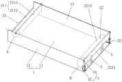
Fig. 1 is a schematic structural view of an adjustable precast concrete slab casting mold according to an embodiment of the present invention;
FIG. 2 is an enlarged view of a portion of FIG. 1 at A;
FIG. 3 is an enlarged view of a portion of FIG. 1 at B;
FIG. 4 is a cross-sectional view of an adjustable precast concrete panel casting mold provided in accordance with an embodiment of the present invention;
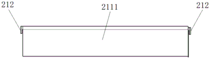
fig. 5 is a schematic view of the connection of the first riser and the stop provided by an embodiment of the present invention;
FIG. 6 is a schematic structural view of a third retaining member according to embodiments of the present invention;
FIG. 7 is a schematic structural diagram of a pallet provided in accordance with an embodiment of the present invention;
fig. 8 is a structural schematic view of a precast concrete panel after forming provided by the present invention.
In the figure:
1-main mould; 3-a fastening assembly; 4-a first locking member; 5-a bracket;
11-a bottom template; 12-sideform;
21-a first template; 22-a second template;
211-a first plate body; 212-a stop;
2111-a first riser; 2112-first transverse plate; 2113-second riser;
221-a second plate body; 222-a connecting portion;
2211-third riser; 2212-second transverse plate; 2213-fourth riser;
31-a second locking member; 32-a third locking member;
321-a locking bolt; 322-a stop nut; 323-a first card; 324-a second card;
51-a first pallet; 52-a second pallet;
100-precast concrete panel.
Detailed Description
The present invention will be described in further detail with reference to the accompanying drawings and examples. It is to be understood that the specific embodiments described herein are merely illustrative of the utility model and are not limiting of the utility model. It should be further noted that, for the convenience of description, only some of the structures related to the present invention are shown in the drawings, not all of the structures.
In the description of the present invention, unless expressly stated or limited otherwise, the terms "connected," "connected," and "fixed" are to be construed broadly, e.g., as meaning permanently connected, removably connected, or integral to one another; can be mechanically or electrically connected; either directly or indirectly through intervening media, either internally or in any other relationship. The specific meanings of the above terms in the present invention can be understood in specific cases to those skilled in the art.
In the present invention, unless otherwise expressly stated or limited, "above" or "below" a first feature means that the first and second features are in direct contact, or that the first and second features are not in direct contact but are in contact with each other via another feature therebetween. Also, the first feature being "on," "above" and "over" the second feature includes the first feature being directly on and obliquely above the second feature, or merely indicating that the first feature is at a higher level than the second feature. A first feature being "under," "below," and "beneath" a second feature includes the first feature being directly under and obliquely below the second feature, or simply meaning that the first feature is at a lesser elevation than the second feature.
In the description of the present embodiment, the terms "upper", "lower", "left", "right", and the like are used based on the orientations and positional relationships shown in the drawings only for convenience of description and simplification of operation, and do not indicate or imply that the referred device or element must have a specific orientation, be configured and operated in a specific orientation, and thus, should not be construed as limiting the present invention. Furthermore, the terms "first" and "second" are used only for descriptive purposes and are not intended to have a special meaning.
As shown in fig. 1, the present embodiment provides an adjustable precast concrete panel casting mold for casting precast concrete panels 100 having the same width and different lengths. The adjustable precast concrete plate pouring mold comprises a main mold 1 and an adjustable mold.
The main mold 1 includes a bottom mold plate 11 and side mold plates 12 respectively disposed at opposite sides of the bottom mold plate 11. The adjustable die comprises a first die plate 21 and a second die plate 22 with adjustable spacing. Both ends of the first formwork 21 and both ends of the second formwork 22 are respectively connected to the two side formworks 12, so that the bottom formwork 11, the two side formworks 12, the first formwork 21 and the second formwork 22 are surrounded to form a pouring cavity. When the precast concrete slab 100 is poured, firstly, the distance between the first template 21 and the second template 22 is adjusted and fixed according to the length of the precast concrete slab 100, then, a steel reinforcement framework is arranged in a pouring cavity, the thickness of a steel reinforcement protective layer is reserved, and then, concrete slurry is poured in the pouring cavity. After the concrete structure is formed, the formed precast concrete plate 100 is taken out by using hoisting equipment, and finally the main mold 1 and the adjustable mold are cleaned so as to pour the next precast concrete plate 100, so that the precast concrete plates 100 with consistent width and different lengths can be poured without repeatedly assembling and disassembling the templates, the process is simple, the labor intensity is reduced, and the construction efficiency is improved.
Referring to fig. 1, optionally, the second template 22 is connected to the sideform 12 by the fastening assembly 3, and the first template 21 is slidably connected to the sideform 12 to adjust the distance between the second template 22 and the first template 21, which is simple to operate and easy to implement.
Specifically, referring to fig. 1, 2 and 5, the first die plate 21 includes a first plate body 211, and both ends of the first plate body 211 are provided with stoppers 212. The stopping portion 212 is spaced apart from the edge of the first plate body 211 to form a sliding slot. The corresponding sliding grooves are clamped at the edges of one side of the two side templates 12 far away from the bottom template 11 and are in sliding fit with the sliding grooves. Through the cooperation of the sliding grooves and the edges of the side formworks 12, the first formworks 21 can slide along the length direction of the side formworks 12, so that the first formworks are suitable for pouring precast concrete plates 100 with different lengths.
Referring to fig. 2, after the sliding of the first mold plate 21 is stopped, it is fixed to the sideform 12 by the first locking member 4. Specifically, the two first locking members 4 respectively pass through the stopping portions 212 at the two ends of the first plate body 211 and tightly abut against the outer wall of the side mold plate 12 to limit the sliding of the first mold plate 21 relative to the side mold plate 12, so that the operation is convenient and fast, and the efficiency can be improved. The first locking member 4 is preferably a screw.
Referring to fig. 1 and 3, optionally, fastening assembly 3 includes a second retaining member 31. Second template 22 includes second plate body 221, and the both ends of second plate body 221 all are provided with connecting portion 222, and connecting portion 222 sets up with the border interval of second plate body 221 to form first draw-in groove, in the first draw-in groove was all located in the card in the one side border that bottom die plate 11 was kept away from to two side form boards 12, connecting portion 222 passed through second retaining member 31 fixed connection in side form board 12. The stability of the second plate body 221 after being connected with the two sideforms 12 can be increased through the matching of the first clamping groove and the edge of the sideform 12.
Optionally, referring to fig. 1 and 4, the first board body 211 includes a first vertical plate 2111, a first horizontal plate 2112 and a second vertical plate 2113 connected in sequence, the first horizontal plate 2112 is disposed on a side of the first vertical plate 2111 away from the second formwork 22, and the stopping portion 212 is disposed on the first vertical plate 2111. The second plate body 221 includes a third vertical plate 2211, a second horizontal plate 2212 and a fourth vertical plate 2213 which are connected in sequence, the second horizontal plate 2212 is disposed on one side of the third vertical plate 2211 facing the first template 21, and the connecting portion 222 is disposed on the third vertical plate 2211. That is, the first vertical plate 2111, the first transverse plate 2112 and the second vertical plate 2113 are connected to form the first plate body 211 having a step shape, the third vertical plate 2211, the second transverse plate 2212 and the fourth vertical plate 2213 are connected to form the second plate body 221 having a step shape, and as shown in fig. 8, the precast concrete plates 100 after casting are formed, step structures are formed on both sides of each precast concrete plate 100, and two adjacent precast concrete plates 100 can be embedded through the step structures, so that the sealing performance and the stability of the two precast concrete plates 100 after splicing are improved.
Referring to fig. 1 and 6, the fastening assembly 3 further includes a third locking member 32. The third locking member 32 includes a locking bolt 321, a stopper nut 322, and a first catching plate 323 and a second catching plate 324 which are vertically connected. The first clamping plate 323 and the second clamping plate 324 are arranged at one side edge of the sideform 12, the edge of the sideform 12 is clamped between the first clamping plate 323 and the second clamping plate 324, the first clamping plate 323 is attached to the outer wall of the sideform 12, and the second clamping plate 324 is parallel to the third riser 2211 and the fourth riser 2213. The locking bolt 321 sequentially penetrates through the fourth vertical plate 2213 and the second clamping plate 324 and is connected with the stop nut 322 to fix the fourth vertical plate 2213. The second retaining member 31 secures the third riser 2211 to the sideform 12, the third retaining member 32 secures the fourth riser 2213 to the sideform 12, and the second retaining member 31 and third retaining member 32 act together to achieve a secure connection between the second template 22 and the main mould 1.
Referring to fig. 1 and 7, a bracket 5 is further provided between the second template 22 and the bottom template 11. Specifically, the bracket 5 includes a first support plate 51 and a second support plate 52 connected, and the first support plate 51 is disposed in parallel with the second support plate 52. The first support plate 51 has one end connected to the bottom mold plate 11 and the other end supporting the second horizontal plate 2212. The length of the second supporting plate 52 is greater than that of the first supporting plate 51, and one end of the second supporting plate 52 is connected with the bottom form 11, and the other end is attached to one side of the third vertical plate 2211, which faces away from the first form 21. In this embodiment, the first supporting plate 51 and the second supporting plate 52 with different lengths form a second slot, and the connecting position (right angle) of the third vertical plate 2211 and the second horizontal plate 2212 is clamped in the second slot, so as to further improve the stability of the second formwork 22.
Preferably, in this embodiment, the main mold 1 and the adjustable mold are both coated with mold release oil, so that the molded precast concrete panel 100 can be taken out conveniently, and the amount of labor for cleaning in the later period is reduced.
It should be understood that the above-described embodiments of the present invention are merely examples for clearly illustrating the present invention, and are not intended to limit the embodiments of the present invention. Numerous obvious variations, adaptations and substitutions will occur to those skilled in the art without departing from the scope of the utility model. And are neither required nor exhaustive of all embodiments. Any modification, equivalent replacement, and improvement made within the spirit and principle of the present invention should be included in the protection scope of the claims of the present invention.
Claims (10)
1. The utility model provides a precast concrete board pouring mould with adjustable which characterized in that includes:
the main die (1) comprises a bottom die plate (11) and two side die plates (12), wherein the two side die plates (12) are respectively arranged on two opposite sides of the bottom die plate (11) along the width direction of the bottom die plate (11);
the adjustable die comprises a first die plate (21) and a second die plate (22) with adjustable intervals, wherein the first die plate (21) and the second die plate (22) are arranged between the two side die plates (12).
2. The adjustable precast concrete slab casting mold according to claim 1, further comprising a fastening assembly (3), the second formwork (22) being connected to the sideform (12) by the fastening assembly (3), the first formwork (21) being slidably connected to the sideform (12) to adjust a distance between the second formwork (22) and the first formwork (21).
3. The adjustable precast concrete board pouring mold according to claim 2, wherein the first formwork (21) comprises a first formwork body (211), both ends of the first formwork body (211) are provided with stopping parts (212), the stopping parts (212) and the edge of the first formwork body (211) form a sliding groove, and one side edge of the side formwork (12) far away from the bottom formwork (11) is clamped in the sliding groove and is in sliding fit with the sliding groove.
4. The adjustable precast concrete slab casting mold according to claim 3, wherein the first slab body (211) comprises a first vertical plate (2111), a first transverse plate (2112) and a second vertical plate (2113) which are connected in sequence, the first transverse plate (2112) is arranged on one side of the first vertical plate (2111) far away from the second formwork (22), and the stopping portion (212) is arranged on the first vertical plate (2111).
5. The adjustable precast concrete slab casting mold according to claim 3, further comprising a first locking member (4), the first locking member (4) being capable of passing through the stopping portion (212) and abutting against the sideform (12) to limit sliding of the first formwork (21) with respect to the sideform (12).
6. The adjustable precast concrete slab casting mold according to claim 2, wherein the fastening assembly (3) comprises a second locker (31), the second formwork (22) comprises a second formwork body (221), both ends of the second formwork body (221) are provided with connection parts (222), and the connection parts (222) are fixedly connected to the side formwork (12) through the second locker (31).
7. The adjustable precast concrete slab casting mold according to claim 6, wherein the second slab body (221) comprises a third vertical plate (2211), a second transverse plate (2212) and a fourth vertical plate (2213) which are connected in sequence, the second transverse plate (2212) is arranged at one side of the third vertical plate (2211) facing the first formwork (21), and the connecting part (222) is arranged at the third vertical plate (2211).
8. The adjustable precast concrete slab casting mold according to claim 7, wherein the fastening assembly (3) further comprises a third locking member (32), the third locking member (32) comprises a locking bolt (321), a stop nut (322), a first clamping plate (323) and a second clamping plate (324) which are vertically connected, one side edge of the side form (12) is clamped between the first clamping plate (323) and the second clamping plate (324), and the locking bolt (321) sequentially penetrates through the fourth vertical plate (2213) and the second clamping plate (324) and is connected with the stop nut (322).
9. The adjustable precast concrete slab casting mold according to claim 7, further comprising a bracket (5), wherein the bracket (5) comprises a first supporting plate (51) and a second supporting plate (52) which are connected, the first supporting plate (51) is supported between the second cross plate (2212) and the bottom formwork (11), one end of the second supporting plate (52) is connected with the bottom formwork (11), and the other end is abutted against one side of the third vertical plate (2211) which faces away from the first formwork (21).
10. The adjustable precast concrete panel casting mold according to any one of claims 1 to 9, wherein the main mold (1) and the adjustable mold are coated with a mold release oil.
Priority Applications (1)
| Application Number | Priority Date | Filing Date | Title |
|---|---|---|---|
| CN202122016976.6U CN215790616U (en) | 2021-08-25 | 2021-08-25 | Adjustable precast concrete slab pouring mold |
Applications Claiming Priority (1)
| Application Number | Priority Date | Filing Date | Title |
|---|---|---|---|
| CN202122016976.6U CN215790616U (en) | 2021-08-25 | 2021-08-25 | Adjustable precast concrete slab pouring mold |
Publications (1)
| Publication Number | Publication Date |
|---|---|
| CN215790616U true CN215790616U (en) | 2022-02-11 |
Family
ID=80151449
Family Applications (1)
| Application Number | Title | Priority Date | Filing Date |
|---|---|---|---|
| CN202122016976.6U Expired - Fee Related CN215790616U (en) | 2021-08-25 | 2021-08-25 | Adjustable precast concrete slab pouring mold |
Country Status (1)
| Country | Link |
|---|---|
| CN (1) | CN215790616U (en) |
Cited By (3)
| Publication number | Priority date | Publication date | Assignee | Title |
|---|---|---|---|---|
| CN114592682A (en) * | 2022-02-23 | 2022-06-07 | 中建八局第一建设有限公司 | Concrete pouring mould for building construction based on quick disassembly |
| CN114800789A (en) * | 2022-03-29 | 2022-07-29 | 浙江捷城建筑科技有限公司 | PC component mould fixer |
| CN119036607A (en) * | 2024-07-12 | 2024-11-29 | 宁波建工工程集团有限公司 | Size-adjustable building lightweight concrete precast slab preparation mold and application method thereof |
-
2021
- 2021-08-25 CN CN202122016976.6U patent/CN215790616U/en not_active Expired - Fee Related
Cited By (6)
| Publication number | Priority date | Publication date | Assignee | Title |
|---|---|---|---|---|
| CN114592682A (en) * | 2022-02-23 | 2022-06-07 | 中建八局第一建设有限公司 | Concrete pouring mould for building construction based on quick disassembly |
| CN114592682B (en) * | 2022-02-23 | 2023-07-07 | 中建八局第一建设有限公司 | Concreting molds for building construction based on quick disassembly |
| CN114800789A (en) * | 2022-03-29 | 2022-07-29 | 浙江捷城建筑科技有限公司 | PC component mould fixer |
| CN114800789B (en) * | 2022-03-29 | 2023-12-26 | 浙江捷城建筑科技有限公司 | A PC component mold holder |
| CN119036607A (en) * | 2024-07-12 | 2024-11-29 | 宁波建工工程集团有限公司 | Size-adjustable building lightweight concrete precast slab preparation mold and application method thereof |
| CN119036607B (en) * | 2024-07-12 | 2025-11-25 | 宁波建工工程集团有限公司 | Adjustable-size lightweight precast concrete slab preparation mold and its usage method |
Similar Documents
| Publication | Publication Date | Title |
|---|---|---|
| CN112726878A (en) | Formwork-erecting-free construction method for masonry filler wall constructional column, prefabricated module and mould | |
| CN111300606A (en) | Prefabricated high-precision high-speed magnetic suspension track beam slab mold and prefabricating method thereof | |
| WO2020134240A1 (en) | Vertical mold for producing prefabricated component | |
| CN111719849A (en) | A primary and secondary beam forming structure of PC laminated beam and its construction method | |
| CN211682694U (en) | A prefabricated formwork system for a laminated slab beam factory assembly line | |
| CN211114798U (en) | Kitchen and bathroom board descending and shaping die | |
| CN111576236A (en) | An installation method of an integral prefabricated bridge deck auxiliary structure | |
| CN204199687U (en) | A kind of bath is fallen plate-girder side shaping tool formula between defending and is hung die device | |
| WO2020134239A1 (en) | Side mold fixing method for production of prefabricated component | |
| CN107989224B (en) | Connecting mechanism for wall corner of assembled house and construction process of connecting mechanism | |
| CN209633293U (en) | A vertical mold for producing prefabricated components | |
| CN119466296A (en) | A type of assembled composite floor slab cast-in-place belt fixed formwork hanging device and construction method | |
| CN210597794U (en) | Connecting device of prefabricated plate | |
| CN204728698U (en) | The closed formwork structure of a kind of concrete suspension bridging piece | |
| CN116122565B (en) | A device for installing and positioning a secondary cast-in-place anti-slope formwork for a floor and a construction method thereof | |
| CN207643373U (en) | A kind of prefabricated anchor block adjustable composite steel form | |
| CN217759995U (en) | Post-cast strip support-free assembly | |
| CN215549667U (en) | Reinforcing bar rack of prefabricated wallboard | |
| CN116290349A (en) | Super-high cross-section clear-faced concrete double-beam stacked double-beam slab without open joint construction method | |
| CN117431787A (en) | Large-capacity ballastless track bed and its construction method | |
| CN112096072B (en) | Beam slab lagging wall column same-layer synchronous concrete pouring method for building machine | |
| CN116657791A (en) | Anti-buckling steel plate shear wall and its manufacturing method and installation method | |
| CN211306723U (en) | Fastening device for prefabricated formwork production | |
| CN210738080U (en) | Support connection system of superimposed sheet and cast-in-place board junction | |
| CN115288333A (en) | One-time pouring forming wall body with sandwich built-in heat preservation and disassembly-free template and construction method |
Legal Events
| Date | Code | Title | Description |
|---|---|---|---|
| GR01 | Patent grant | ||
| GR01 | Patent grant | ||
| CF01 | Termination of patent right due to non-payment of annual fee |
Granted publication date: 20220211 |
|
| CF01 | Termination of patent right due to non-payment of annual fee |