CN215789583U - Disassembling tool for brake of hydroelectric generating set - Google Patents
Disassembling tool for brake of hydroelectric generating set Download PDFInfo
- Publication number
- CN215789583U CN215789583U CN202121994024.5U CN202121994024U CN215789583U CN 215789583 U CN215789583 U CN 215789583U CN 202121994024 U CN202121994024 U CN 202121994024U CN 215789583 U CN215789583 U CN 215789583U
- Authority
- CN
- China
- Prior art keywords
- tray
- brake
- fixed
- adjusting
- side vertical
- Prior art date
- Legal status (The legal status is an assumption and is not a legal conclusion. Google has not performed a legal analysis and makes no representation as to the accuracy of the status listed.)
- Active
Links
- 239000004677 Nylon Substances 0.000 claims description 8
- 229920001778 nylon Polymers 0.000 claims description 8
- 238000000034 method Methods 0.000 abstract description 11
- XLYOFNOQVPJJNP-UHFFFAOYSA-N water Substances O XLYOFNOQVPJJNP-UHFFFAOYSA-N 0.000 description 7
- 238000009434 installation Methods 0.000 description 6
- 238000012423 maintenance Methods 0.000 description 4
- 238000005096 rolling process Methods 0.000 description 4
- 229910000831 Steel Inorganic materials 0.000 description 2
- 230000006378 damage Effects 0.000 description 2
- 230000005484 gravity Effects 0.000 description 2
- 238000011418 maintenance treatment Methods 0.000 description 2
- 239000010959 steel Substances 0.000 description 2
- 208000027418 Wounds and injury Diseases 0.000 description 1
- 238000010276 construction Methods 0.000 description 1
- 238000007796 conventional method Methods 0.000 description 1
- 238000010586 diagram Methods 0.000 description 1
- 208000014674 injury Diseases 0.000 description 1
- 230000002441 reversible effect Effects 0.000 description 1
- 239000003381 stabilizer Substances 0.000 description 1
- 238000003466 welding Methods 0.000 description 1
Images




Landscapes
- Hydraulic Turbines (AREA)
Abstract
The utility model provides an assembly and disassembly tools of hydroelectric set stopper, its main points lie in that it comprises bearing roller, tray, side riser, side stand, and two side risers and two side stands are fixed in four directions below the tray respectively, and the side riser is fixed with tray below connecting plate for connecting bolt connection, and the side stand is fixed in the tray through lock nut, adjusting screw, adjusting nut, and a plurality of outer bearing rollers are fixed in the top of tray. The disassembling tool designed by the utility model is designed into a detachable tool, has simple structure, good adaptability and easy assembly, and avoids the difficulty in moving, carrying and constructing caused by overlarge overall weight of the tool. And the level and the height of the tray can be adjusted through the adjusting bolts on the side vertical plates and the adjusting nuts on the side vertical columns, so that unsafe factors possibly existing in the process of using other articles for cushioning are avoided. During operation, a plurality of working surfaces do not need to be shut down and matched and crossed, the working efficiency is greatly improved, and various unsafe factors existing in the conventional operation method are effectively avoided.
Description
Technical Field
The utility model belongs to the field of installation and maintenance of a water-turbine generator set, and particularly relates to a special tool for disassembling and assembling a mechanical brake of the water-turbine generator set.
Background
The hydroelectric generating set is bulky, the diameter of a rotor of the hydroelectric generating set generally exceeds 4 meters, and the transportation and the installation of the volume and the weight of each part cannot be carried out manually. The brake is an important component of the water turbine generator set and is a quick-wear part, the seal of the piston cylinder is easy to damage and needs to be replaced, and whether the installation of the brake is correct and reliable directly influences whether the generator set can be safely and stably stopped. Therefore, the brake needs to be disassembled, inspected, adjusted and replaced during the assembly and maintenance of the unit, and the problem brake needs to be replaced. As shown in fig. 4, taking a reversible generator set with a single machine capacity of 300MW as an example, since the brakes are generally installed on the lower frame 12 at the lower part of the rotor of the generator set, and are installed at 8 equal circumferential angles, the volume of the brake 15 is about: the length is 500mm, the width is 460mm, the height is 380mm, the weight is up to 525kg, the lower frame 12 of the rotor of the unit with the depth of 6.5 meters from the surface is installed, the length of the space for the inlet and outlet of the lower frame is only 1100mm, the operation space is narrow, the brake is heavy (generally more than 0.5 ton), and therefore, how to safely, reliably and quickly disassemble and assemble in the installation and maintenance process is a technical problem.
Conventionally, in each hydraulic power plant, the brake is attached and detached by binding the brake to the lower portion of the rotor and then rotating the rotor. The specific disassembly method comprises the following steps: firstly, the air pressure in the brake is relieved to ensure that the brake is not pressurized, and the brake plate of the brake is separated from the brake ring plate at the lower part of the rotor. And secondly, removing the connection between the brake and the lower frame. And thirdly, hanging a chain block 14 by taking a vent hole at the lower end of the rotor as a hanging point (in fig. 5, the dotted line is the position of the chain block in the prior art), hanging the brake at the lower part of the rotor by using the chain block and the hanging strip, and separating the brake from the lower rack, wherein the hanging strip moves horizontally and bears the gravity of the brake, the pulling force borne by the hanging strip is an oblique force, and the gap between the brake and a brake ring plate at the lower part of the rotor is small and generally between 15mm and 20mm, so that the brake is easy to clamp during the step, the pulled brake swings due to the flexibility of the hanging strip, the position, the length and the hanging point of the chain block bound by the hanging strip are highly required, and great difficulty exists during specific operation. And fourthly, after the brake is lifted to be separated from the lower rack, starting the high-top oil pump to enable the thrust head to be separated from the thrust tile, so that the rotating part of the whole unit is suspended, and the rotor can rotate. And fifthly, arranging a plurality of persons to jointly push the rotor, and driving a brake hung at the lower part of the rotor to rotate along with the rotor by the rotation of the rotor so that the brake is rotated out of the lower frame supporting leg. And sixthly, closing the high-top oil pump after the brake is completely rotated out of the lower rack supporting legs to enable the rotating part to fall down, and then using the chain block to slowly fall down the brake, wherein the brake is located below the rotor, and the brake is most convenient to place between the two lower rack supporting legs, but the upper part of the operation space is limited by the rotor, the left part and the right part of the operation space are limited by the two lower rack supporting legs, and the operation space is extremely narrow and small and is suppressed, so that the brake is generally and directly lowered to a waterwheel room with a wide lower part by the chain block for maintenance.
When the brake is reinstalled, the brake is reinstalled by a method of rotor rotation, and the brake needs to be pushed in by manual assistance, so that the labor intensity is high. The hoisting points of the hanging belt and the chain block need to be accurately calculated to prevent the brake from falling onto the supporting leg of the lower frame to cause rework.
In summary, when the conventional method is used for disassembling and assembling the brake, the operation space is narrow, the operation of constructors is inconvenient, and the phenomenon of rework is easy to occur during the installation, so that the progress of the construction period is influenced. Meanwhile, the risk of cross operation exists in the process of starting and stopping the high-lift oil pump and rotating the rotor, and the risk of brake swing, collision and even falling exists when the brake is lifted and the rotor is rotated, so that serious personal injury can be caused.
SUMMERY OF THE UTILITY MODEL
The utility model aims to solve the problems in the existing process of disassembling and assembling a brake of a water-turbine generator set, and provides a safe, efficient and quick disassembling and assembling tool for the brake of the water-turbine generator set.
The technical scheme adopted by the utility model is that the disassembling tool for the brake of the hydroelectric generating set is characterized by comprising carrier rollers, a tray, two side vertical plates and side vertical columns, wherein the two side vertical plates and the two side vertical columns are respectively fixed in four directions below the tray, the side vertical plates and a connecting plate below the tray are fixedly connected through connecting bolts, the side vertical columns are fixed on the tray through locking nuts, adjusting screws and adjusting nuts, and a plurality of outer carrier rollers are fixed above the tray.
The utility model forms a stable platform by arranging the tray, the two side vertical plates and the two side vertical columns, and fixes the platform with the lower frame and the oil groove, so that the stable connection is formed between the platform and the hydraulic generator, and when the brake is disassembled and assembled, the friction force of the brake moving on the tray is reduced by the rotation of the carrier roller in the tray, so that the brake can be easily moved in and out of the tray, and the working efficiency is greatly improved. After the brake is moved to the utility model, the hand chain block (the hand chain block in the solid line in fig. 5 is the hand chain block of the utility model) is conveniently used for hoisting the brake out, the brake is horizontally lowered to a waterwheel room with wide lower part for maintenance treatment, and the hanging belt of the hand chain block only bears the downward gravity at the moment, so that the swinging does not exist, and the hoisting process is stable and safe.
The connecting holes between the upper ends of the side vertical plates and the tray connecting plate are long holes, the connecting holes of the side vertical plates are threaded holes, and adjusting bolts are arranged on the side surfaces of the side vertical plates below the connecting plate. The height of the tray connecting plate can be conveniently adjusted, and the lower end face of the carrier roller and the lower end face of the brake are guaranteed to be horizontal, so that the brake can smoothly enter and exit.
The lower end of the side vertical plate is provided with a clamping groove for clamping the lower rack supporting leg and is tightly propped by a propping bolt 6. The fixing bayonet is creatively manufactured according to the actual situation, and the position of a frame foot can not be stably placed due to the complex internal structure of the water turbine generator set, so that the lower frame supporting leg close to the brake in position in the water turbine generator set is used as a fixing part, the stability and the sufficient width of the fixing frame are ensured, meanwhile, the other end of the frame is fixed on the upper edge of the oil groove, the stable fixation of the assembling and disassembling tool of the brake of the water turbine generator set is ensured, meanwhile, the carrier roller on the upper surface of the assembling and disassembling tool of the brake of the water turbine generator set is enabled to have the sufficient length and width, and the stable movement of the brake is ensured.
The lower end of the side upright post is provided with an anti-skid nylon cushion block. Because the side stand is stood on the upper edge of the oil groove, oil stain is difficult to avoid, and the bottom of the side stand is specially designed with an anti-slip nylon cushion block for skid resistance.
This application is used for fixed stabilizer blade to be side riser, side stand, their highly all is according to the high design between fixed position and the stopper fixed platform in the stopper will be demolishd, with the upper surface and the stopper lower surface minimum level of guaranteeing the bearing roller, because hydroelectric set probably has the error in the installation, but this application has all designed the structure of fine setting height on the fixed position of side riser and side stand direction of height very much, the purpose is the upper surface and the stopper lower surface minimum level of guaranteeing the bearing roller.
The transverse two sides of the tray are provided with the baffle plates and the grooves for placing the rolling bearings of the carrier roller, so that the carrier roller is convenient to disassemble and place, and the carrier roller is prevented from being displaced when in use.
The tray is furnished with the screw hole with the side column junction, during the connection with the threaded hole that the adjusting screw upper end screw in tray corresponds, reuse lock nut locking is fixed. The side upright posts are upright posts with holes, and the lower ends of the adjusting screws are directly inserted into the upright posts. Adjusting nuts are arranged in the middle of the adjusting screw rods, the level and the height of the tray can be adjusted by rotating the adjusting nuts, and the tray is prevented from being unevenly stressed due to inclination. The bottom of the side upright post is provided with a nylon cushion block, so that the side upright post can be prevented from sliding when being supported at the edge of the oil groove, and danger is caused.
The disassembling tool designed by the utility model is designed into a detachable tool, is easy to assemble, and avoids the difficulty in moving, carrying and constructing caused by overlarge overall weight of the tool. And the level and the height of the tray can be adjusted through the adjusting bolts on the side vertical plates and the adjusting nuts on the side vertical columns, so that unsafe factors possibly existing in the process of using other articles for cushioning are avoided.
The utility model has the advantages that: simple structure, good adaptability, convenient operation, safety and reliability. During the use, through adjusting bolt and adjusting nut adjustment tray's height and level, rely on the rotation flexibility of bearing roller again, can be light pull out the stopper or push. During operation, a plurality of working surfaces do not need to be shut down and matched and crossed, the working efficiency is greatly improved, and various unsafe factors existing in the conventional operation method are effectively avoided.
Description of the drawings:
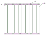
FIG. 1 is a front view of the present invention
FIG. 2 is a left side view of FIG. 1
FIG. 3 is a top view of FIG. 1
FIG. 4 is a state diagram of the present invention
FIG. 5 is a partial enlarged view of FIG. 4
Wherein: the device comprises a carrier roller 1, a pallet 2, a connecting plate 21, a baffle 22, a limit baffle 23, an adjusting bolt 3, a connecting screw rod 4, a side vertical plate 5, a clamping groove 51, a fixing block 52, a puller bolt 6, a locking nut 7, an adjusting screw rod 8, an adjusting nut 9, a nylon cushion block 10, a side upright post 11, a lower frame supporting leg 12, an oil groove 13, a chain block 14 and a brake 15.
Detailed Description
The utility model is further described below with reference to the accompanying drawings.
As shown in fig. 1, 2 and 3, the disassembling tool for the brake of the hydroelectric generating set comprises a carrier roller 1, a tray 2, an adjusting bolt 3, a connecting screw rod 4, a side vertical plate 5, a jacking bolt 6, a locking nut 7, an adjusting screw rod 8, an adjusting nut 9, a nylon cushion block 10 and a side upright post 11. The carrier roller 1 is a seamless steel pipe, and two ends of the carrier roller are provided with rolling bearings, so that the carrier roller 1 can roll easily. The tray 2 is a rectangular frame, the transverse two sides of the frame are provided with baffle plates 22, the baffle plates are provided with grooves and are used for placing rolling bearings of the carrier roller 1, the carrier roller is convenient to disassemble and place, and the carrier roller 1 can be prevented from shifting or sliding under the rotating condition.
As shown in fig. 4 and 5, because the volume of the utility model is greatly different compared with that of a water turbine generator set, fig. 4 and 5 are only partial views, the side upright posts 11 are arranged at two sides of the lower part of the tray 2 close to the edge of the oil groove 13 of the generator set, the tray 2 is provided with threaded holes matched with the adjusting screw 8 at the joint part of the side upright posts 11, and the adjusting screw 8 is a fine-tooth full-tooth screw. During connection, the upper end of the adjusting screw 8 is screwed into the corresponding threaded hole of the tray 2 and then locked and fixed by the locking nut 7. The side upright post 11 is an upright post with a hole, and the lower end of the adjusting screw 8 is inserted into the hole of the side upright post 11. The adjusting nut 9 is arranged in the middle of the adjusting screw 8, and the level and height of the tray 2 can be adjusted by rotating the adjusting nut 9, so that the tray is prevented from being inclined and stressed unevenly. The bottom of the side upright post 11 is provided with a nylon cushion block 10, which can prevent the side upright post 11 from sliding when being supported at the edge of the oil groove, thereby causing danger.
In the operation process, the level and the height of the tray 2 are adjusted by adjusting the adjusting bolts 3 on the side vertical plates 5 and the adjusting nuts 9 on the side vertical columns 11, generally, the lowest level of the upper surface of the carrier roller and the lower surface of the brake is ensured, so that the brake can pass in and out without adjusting equipment, and the brake can be quickly and effectively moved out or installed in place by the rotation of the carrier roller 1.
The step of removing or reinstalling the brake by using the special tool comprises the following steps:
a) releasing the air pressure in the brake to ensure that the brake is not pressurized, and separating a brake plate of the brake from a brake ring plate at the lower part of the rotor;
b) removing a connecting screw rod of the brake and the lower frame;
c) a special disassembling tool of the brake of the water turbine generator set is fixed between the lower frame 12 and the oil groove 13 and is positioned below the brake 15;
d) erecting a 1t small jack on the rear side of the brake by using the lower wind shield upright post as a stress point, and ejecting the brake;
e) the brake is safely, easily and quickly pulled out or pushed in by the rotation of the carrier roller 1. Then, a chain block (the chain block in a solid line in the figure is the chain block of the utility model) is used for hoisting out the brake, the brake is horizontally lowered to a waterwheel room with a wide lower part for maintenance treatment,
step c) fixing the special disassembling tool of the hydroelectric generating set brake between the lower frame and the oil groove, and is positioned below the brake means that the upper end of the side vertical plate 5 is connected with a connecting plate 21 below the tray 2 by a connecting screw rod 4, and the connecting screw rod 4 is pre-tightened; clamping a clamping groove 51 at the lower end of the side vertical plate 5 into a lower rack supporting leg, and jacking by a jacking bolt 6 to prevent slipping; screwing the adjusting screw 8 into the matched threaded hole of the tray 2, locking the threaded hole by using the locking nut 7, and then inserting the adjusting screw 8 into the side upright post 11 with the hole; placing and supporting the side upright posts 11 on an oil groove through nylon cushion blocks 10; sequentially placing the carrier rollers 1 in the grooves of the tray 2 to enable the carrier rollers 1 to normally rotate; adjusting the height of the tray 2 to a proper position and keeping the tray horizontal by using the adjusting bolts 3 and the adjusting nuts 9; the connecting screw rod 4 is locked, and the side vertical plate 5 and the side upright post 11 are checked and confirmed to be installed correctly and firmly.
Claims (4)
1. The utility model provides an assembly and disassembly tools of hydroelectric set stopper, it comprises bearing roller (1) its characterized in that, tray (2), side riser (5), side stand (11), two side risers and two side stands are fixed in four directions in tray below respectively, side riser (5) are connected fixedly with connecting bolt (4) below the tray connecting plate (21), side stand (11) are fixed in the tray through lock nut (7), adjusting screw (8), adjusting nut (9), a plurality of outer bearing rollers are fixed in the top of tray.
2. The disassembling tool for the hydroelectric generating set brake according to claim 1, wherein the upper end of the side vertical plate (5) is provided with a fixed connection threaded hole connected with the tray connecting plate (21), the hole on the connecting plate (21) is a long hole, and the side surface of the side vertical plate below the connecting plate is provided with an adjusting bolt (3).
3. The disassembling tool for the brake of the hydroelectric generating set according to claim 1, wherein the lower end of the side vertical plate (5) is provided with a clamping groove (51) for clamping a lower frame supporting leg and is tightly jacked by a jacking bolt (6).
4. The disassembling tool of the hydroelectric generating set brake according to claim 1, characterized in that the lower end of the side upright post (11) is equipped with an anti-skid nylon cushion block (10).
Priority Applications (1)
| Application Number | Priority Date | Filing Date | Title |
|---|---|---|---|
| CN202121994024.5U CN215789583U (en) | 2021-08-24 | 2021-08-24 | Disassembling tool for brake of hydroelectric generating set |
Applications Claiming Priority (1)
| Application Number | Priority Date | Filing Date | Title |
|---|---|---|---|
| CN202121994024.5U CN215789583U (en) | 2021-08-24 | 2021-08-24 | Disassembling tool for brake of hydroelectric generating set |
Publications (1)
| Publication Number | Publication Date |
|---|---|
| CN215789583U true CN215789583U (en) | 2022-02-11 |
Family
ID=80150467
Family Applications (1)
| Application Number | Title | Priority Date | Filing Date |
|---|---|---|---|
| CN202121994024.5U Active CN215789583U (en) | 2021-08-24 | 2021-08-24 | Disassembling tool for brake of hydroelectric generating set |
Country Status (1)
| Country | Link |
|---|---|
| CN (1) | CN215789583U (en) |
Cited By (1)
| Publication number | Priority date | Publication date | Assignee | Title |
|---|---|---|---|---|
| CN113601454A (en) * | 2021-08-24 | 2021-11-05 | 中国水利水电第十六工程局有限公司 | Disassembling tool and disassembling method for brake of hydroelectric generating set |
-
2021
- 2021-08-24 CN CN202121994024.5U patent/CN215789583U/en active Active
Cited By (1)
| Publication number | Priority date | Publication date | Assignee | Title |
|---|---|---|---|---|
| CN113601454A (en) * | 2021-08-24 | 2021-11-05 | 中国水利水电第十六工程局有限公司 | Disassembling tool and disassembling method for brake of hydroelectric generating set |
Similar Documents
| Publication | Publication Date | Title |
|---|---|---|
| CN111151581B (en) | Manual roll changing device and roll changing method for two-roller rolling mill | |
| CN214573987U (en) | Conveniently adjusted lattice column positioning frame | |
| CN105971307A (en) | Temporary support device for frame-type steel-structure combined oblique stand column and construction method | |
| CN113601454A (en) | Disassembling tool and disassembling method for brake of hydroelectric generating set | |
| CN112431393A (en) | Portable foldable lifting platform | |
| CN112796921B (en) | Vertical water turbine guide vane overhauling rapid assembling and disassembling platform and assembling method thereof | |
| CN109986524A (en) | A kind of hanging ladder tooling peculiar to vessel and its application method | |
| CN210888010U (en) | construction operation rack | |
| CN217046336U (en) | Platform is overhauld in hydraulic generator air brake dismouting | |
| CN218226536U (en) | Leveling device for multistage pump rotor | |
| KR100823859B1 (en) | How to inspect and repair the lower surface of the elevated road and its inspection and repair device | |
| CN221854020U (en) | A kind of installation equipment of prestressed jack | |
| CN113716483B (en) | Beam maintenance combined tool and maintenance method of pumping unit | |
| CN218406353U (en) | Lifting scaffold for constructional engineering | |
| CN114961292B (en) | Device for heavy steel beam construction, heavy steel beam and assembly method | |
| CN209948898U (en) | Rotor brake ring plate assembly and disassembly tools | |
| CN215803470U (en) | Reinforced concrete supporting structure for building construction technology | |
| CN112844263B (en) | Method for disassembling and assembling components in large chemical tower | |
| CN211967409U (en) | Thrust bearing bush assembling and disassembling tool | |
| CN209989136U (en) | Cantilever type guide rod device and submersible water impeller applying same | |
| CN223838663U (en) | Prefabricated component repair supporting device | |
| CN220928639U (en) | A scaffold | |
| CN220395125U (en) | Scaffold for building construction | |
| CN217758771U (en) | Rapid assembly moving platform for piling at breach | |
| CN222509189U (en) | Photovoltaic bracket capable of quickly installing photovoltaic panels |
Legal Events
| Date | Code | Title | Description |
|---|---|---|---|
| GR01 | Patent grant | ||
| GR01 | Patent grant |