CN215787719U - Robot arm welding platform with welding slag clearance structure - Google Patents
Robot arm welding platform with welding slag clearance structure Download PDFInfo
- Publication number
- CN215787719U CN215787719U CN202122277327.1U CN202122277327U CN215787719U CN 215787719 U CN215787719 U CN 215787719U CN 202122277327 U CN202122277327 U CN 202122277327U CN 215787719 U CN215787719 U CN 215787719U
- Authority
- CN
- China
- Prior art keywords
- fixedly connected
- assembly
- pressure
- collecting box
- plate
- Prior art date
- Legal status (The legal status is an assumption and is not a legal conclusion. Google has not performed a legal analysis and makes no representation as to the accuracy of the status listed.)
- Active
Links
- 238000003466 welding Methods 0.000 title claims abstract description 71
- 239000002893 slag Substances 0.000 title claims abstract description 55
- 238000004140 cleaning Methods 0.000 claims abstract description 62
- 230000005540 biological transmission Effects 0.000 claims abstract description 51
- 230000008093 supporting effect Effects 0.000 claims abstract description 14
- 239000002184 metal Substances 0.000 claims description 3
- 230000000694 effects Effects 0.000 abstract description 10
- 230000005012 migration Effects 0.000 abstract description 2
- 238000013508 migration Methods 0.000 abstract description 2
- 238000009423 ventilation Methods 0.000 description 8
- 238000000034 method Methods 0.000 description 7
- 230000008569 process Effects 0.000 description 5
- 230000009471 action Effects 0.000 description 3
- 239000000428 dust Substances 0.000 description 2
- 238000003825 pressing Methods 0.000 description 2
- 239000000779 smoke Substances 0.000 description 2
- 230000009286 beneficial effect Effects 0.000 description 1
- 230000003139 buffering effect Effects 0.000 description 1
- 230000002708 enhancing effect Effects 0.000 description 1
- 238000001914 filtration Methods 0.000 description 1
- 230000006872 improvement Effects 0.000 description 1
- 230000004048 modification Effects 0.000 description 1
- 238000012986 modification Methods 0.000 description 1
- 230000002035 prolonged effect Effects 0.000 description 1
- 230000001105 regulatory effect Effects 0.000 description 1
Images


Landscapes
- Arc Welding In General (AREA)
Abstract
The utility model discloses a robot arm welding platform with a welding slag cleaning structure, which relates to the technical field of welding platforms and comprises a collecting box, wherein a supporting platform is arranged at the top of the collecting box, a baffle is fixedly connected to the top of the collecting box, a transmission assembly is arranged on the back of the collecting box, a pneumatic rod is fixedly connected to the top of the transmission assembly, a lifting plate is fixedly connected to the top end of the pneumatic rod, and a cleaning assembly is arranged at the bottom of the lifting plate through a pressure assembly. This practicality has played the effect of convenient clearance welding slag through setting up collecting box, supporting platform, baffle, drive assembly, air pressure bar, lifter plate and clearance subassembly, adopts the high-speed rotation of clearance subassembly to brush the welding slag that falls, improves the efficiency of clearance welding slag, utilizes drive assembly to drive clearance subassembly horizontal migration, and the welding slag clearance is more thorough, utilizes the collecting box conveniently to collect the welding slag, utilizes the baffle to block the welding slag, avoids splashing, improves the security.
Description
Technical Field
The utility model relates to the technical field of welding platforms, in particular to a robot arm welding platform with a welding slag cleaning structure.
Background
When the robot arm is welded, the welding platform is needed to bear welding parts of the robot arm, and welding work is facilitated.
The patent of current chinese patent document publication number CN212634815U discloses a robot welding platform, including the mount and install the rigid board of placing on the mount, place and be provided with the welded plate mount on the board, install the support on the welded plate mount, be provided with the ventilation pipe subassembly on the support and adjust the regulating part of ventilation pipe subassembly swing angle, the ventilation pipe subassembly is equipped with the air intake, the last intercommunication of ventilation pipe subassembly has updraft ventilator, is provided with filter in the ventilation pipe subassembly. The ventilation pipe assembly is characterized in that the air draft device is started, harmful smoke and dust generated during welding of the welded plate are sucked into the ventilation pipe assembly and discharged after being filtered by the filtering piece arranged in the ventilation pipe assembly, and therefore the harmful smoke and dust generated during welding of the welded plate are not prone to affecting air in a workshop.
However, the above documents lack a structure for cleaning and collecting the welding slag, which is inconvenient for cleaning the welding slag and affects the welding operation of the robot arm.
SUMMERY OF THE UTILITY MODEL
The utility model aims to provide a robot arm welding platform with a welding slag cleaning structure, which aims to solve the problems in the background technology.
In order to solve the technical problems, the utility model provides the following technical scheme: the utility model provides a robot arm welded platform with welding slag clearance structure, includes the collecting box, the top of collecting box is provided with supporting platform, the top fixedly connected with baffle of collecting box, the back of collecting box is provided with drive assembly, drive assembly's top fixedly connected with atmospheric pressure pole, the top fixedly connected with lifter plate of atmospheric pressure pole, the bottom of lifter plate is provided with the clearance subassembly through pressure assembly, the equal fixedly connected with cushion in four corners of collecting box bottom.
Furthermore, the top of the supporting platform is provided with a triangular supporting sharp corner, and the supporting platform is made of a hollow high-temperature-resistant metal plate.
Further, the transmission assembly comprises a transmission case, a transmission motor is fixedly connected to the left side inside the transmission case, a first bevel gear is fixedly connected to an output shaft of the transmission motor, a second bevel gear is meshed to the right side of the first bevel gear, a lead screw is fixedly connected to the axis of the second bevel gear, a moving block is connected to the surface of the lead screw through lead screw nut transmission, a fixed plate is fixedly connected to the top of the moving block, and the top of the fixed plate is fixedly connected to the bottom end of the air pressure rod.
Furthermore, the surface of the transmission box is fixedly connected with the back of the collection box, two ends of the lead screw are rotatably connected with two sides of the inner wall of the transmission box, and the top of the transmission box is provided with a moving groove matched with the moving block.
Further, the middle part fixedly connected with slider of fixed plate bottom, the bottom of slider runs through the transmission case and extends to the inside of transmission case, the slider is located the inside one end of transmission case and runs through there is the slide bar, the both ends of slide bar respectively with the both sides fixed connection of transmission case inner wall.
Further, the cleaning assembly comprises a power box, the top of the power box is rotatably connected with the bottom of the pressure assembly, a power motor is fixedly connected to the right side of the bottom of the inner wall of the power box, a third bevel gear is fixedly connected with an output shaft of the power motor, a fourth bevel gear is meshed with the bottom of the third bevel gear, a rotating shaft is fixedly connected to the axis of the fourth bevel gear, the top end of the rotating shaft is rotatably connected with the top of the inner wall of the power box, a cleaning plate is fixedly connected to the bottom end of the rotating shaft, and a plurality of cleaning bristles are arranged at the bottom of the cleaning plate.
Further, the pressure assembly comprises a sleeve, a pressure rod penetrates through the left end of the sleeve, one end of the pressure rod, which is located inside the sleeve, is fixedly connected with a pressure plate, a pressure spring is fixedly connected between the right side of the pressure plate and the right side of the inner wall of the sleeve, one ends, which are far away from the pressure rod and the sleeve, are fixedly connected with connecting plates, two connecting plates are rotatably connected with a first connecting rod and a second connecting rod, the top ends of the two second connecting rods are rotatably connected with the bottom of the lifting plate, and the bottom ends of the two first connecting rods are rotatably connected with the two sides of the top of the cleaning assembly.
Compared with the prior art, the utility model has the following beneficial effects:
1. this robot arm welded platform with welding slag clearance structure, through setting up the collecting box, supporting platform, the baffle, drive assembly, the air pressure bar, lifter plate and clearance subassembly have played the effect of convenient clearance welding slag, adopt the high-speed welding slag that falls of brush of clearance subassembly, improve the efficiency of clearance welding slag, utilize drive assembly to drive clearance subassembly horizontal migration, the welding slag clearance is more thorough, utilize the collecting box conveniently to collect the welding slag, utilize the baffle to block the welding slag, avoid splashing, the security is improved.
2. This robot arm welded platform with welding slag clearance structure has played the effect that strengthens welding slag clearance effect through setting up pressure assembly, and pressure spring's elastic pressure can play the effect that the brush hair was cleaned in the buffer protection simultaneously, and the extension cleans the life of brush hair.
Drawings
The accompanying drawings, which are included to provide a further understanding of the utility model and are incorporated in and constitute a part of this specification, illustrate embodiments of the utility model and together with the description serve to explain the principles of the utility model and not to limit the utility model. In the drawings:
FIG. 1 is a front sectional view of the present invention;
FIG. 2 is a right side view of the present invention;
FIG. 3 is a rear view of the present invention;
FIG. 4 is an enlarged schematic view at A of FIG. 2 of the present invention;
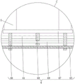
FIG. 5 is an enlarged schematic view of the utility model at B in FIG. 3;
FIG. 6 is an enlarged schematic view of the utility model at C of FIG. 3;
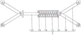
FIG. 7 is a schematic structural view of the pressure assembly of the present invention;
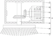
FIG. 8 is a schematic structural view of the cleaning assembly of the present invention.
In the figure: 1. a collection box; 2. a support platform; 3. a baffle plate; 4. a transmission assembly; 41. a transmission case; 42. a drive motor; 43. a first bevel gear; 44. a second bevel gear; 45. a screw rod; 46. a moving block; 47. a fixing plate; 48. a slider; 49. a slide bar; 5. a pneumatic rod; 6. a lifting plate; 7. a pressure assembly; 71. a sleeve; 72. a pressure lever; 73. pressing a plate; 74. a pressure spring; 75. a connecting plate; 76. a first link; 77. a second link; 8. cleaning the assembly; 81. a power box; 82. a power motor; 83. a third bevel gear; 84. a fourth bevel gear; 85. a rotating shaft; 86. cleaning the board; 87. cleaning the bristles; 9. and a cushion block.
Detailed Description
The technical solutions in the embodiments of the present invention will be clearly and completely described below with reference to the drawings in the embodiments of the present invention, and it is obvious that the described embodiments are only a part of the embodiments of the present invention, and not all of the embodiments. All other embodiments, which can be derived by a person skilled in the art from the embodiments given herein without making any creative effort, shall fall within the protection scope of the present invention.
The robot arm welding platform with the welding slag cleaning structure as shown in fig. 1-6 and 8 comprises a collection box 1, a support platform 2 is arranged at the top of the collection box 1, a baffle 3 is fixedly connected to the top of the collection box 1, a transmission component 4 is arranged on the back of the collection box 1, a pneumatic rod 5 is fixedly connected to the top of the transmission component 4, a lifting plate 6 is fixedly connected to the top end of the pneumatic rod 5, a cleaning component 8 is arranged at the bottom of the lifting plate 6 through a pressure component 7, cushion blocks 9 are fixedly connected to four corners of the bottom of the collection box 1, triangular support sharp corners are arranged at the top of the support platform 2, the support platform 2 is made of a hollow high-temperature-resistant metal plate, the transmission component 4 comprises a transmission box 41, a transmission motor 42 is fixedly connected to the left side inside the transmission box 41, and a first bevel gear 43 is fixedly connected to an output shaft of the transmission motor 42, a second bevel gear 44 is engaged on the right side of the first bevel gear 43, a lead screw 45 is fixedly connected to the axis of the second bevel gear 44, a moving block 46 is connected to the surface of the lead screw 45 through lead screw nut transmission, a fixed plate 47 is fixedly connected to the top of the moving block 46, the top of the fixed plate 47 is fixedly connected to the bottom of the pneumatic rod 5, the cleaning assembly 8 comprises a power box 81, the top of the power box 81 is rotatably connected to the bottom of the pressure assembly 7, a power motor 82 is fixedly connected to the right side of the bottom of the inner wall of the power box 81, a third bevel gear 83 is fixedly connected to an output shaft of the power motor 82, a fourth bevel gear 84 is engaged to the bottom of the third bevel gear 83, a rotating shaft 85 is fixedly connected to the axis of the fourth bevel gear 84, the top of the rotating shaft 85 is rotatably connected to the top of the inner wall of the power box 81, and a cleaning plate 86 is fixedly connected to the bottom of the rotating shaft 85, the bottom of the cleaning plate 86 is provided with a plurality of cleaning bristles 87.
The surface of the transmission box 41 is fixedly connected with the back of the collecting box 1, two ends of the screw rod 45 are rotatably connected with two sides of the inner wall of the transmission box 41, and the top of the transmission box 41 is provided with a moving groove matched with the moving block 46.
The middle of the bottom of the fixed plate 47 is fixedly connected with a sliding block 48, the bottom end of the sliding block 48 penetrates through the transmission box 41 and extends to the inside of the transmission box 41, a sliding rod 49 penetrates through one end, located inside the transmission box 41, of the sliding block 48, and two ends of the sliding rod 49 are fixedly connected with two sides of the inner wall of the transmission box 41 respectively.
The implementation mode is specifically as follows: when the device is used, in the process of cleaning welding slag, the air pressure rod 5 is shortened, the air pressure rod 5 drives the lifting plate 6 to move downwards, the lifting plate 6 pushes the cleaning component 8 at the bottom of the pressure component 7 to move downwards, the power motor 82 in the power box 81 is started, the power motor 82 drives the third bevel gear 83 to rotate, the third bevel gear 83 drives the fourth bevel gear 84 to rotate, the fourth bevel gear 84 drives the rotating shaft 85 to rotate, the rotating shaft 85 drives the cleaning plate 86 to rotate, the rotating cleaning plate 86 drives the cleaning bristles 87 to clean the welding slag, the welding slag falls into the collection box 1 from the supporting platform, the welding slag is convenient to collect, meanwhile, the transmission component 4 is started, the transmission motor 42 in the transmission box 41 drives the first bevel gear 43 to rotate, the first bevel gear 43 drives the second bevel gear 44 to rotate, the second bevel gear 44 drives the screw rod 45 to rotate, the screw rod 45 pushes the screw nut on the surface thereof to drive the moving block 46 to move, the movable block 46 drives the fixed plate 47 at the top of the movable block to move, the fixed plate 47 drives the air pressure rod 5 to move, thereby driving the horizontal movement of the cleaning assembly 8, the cleaning of the welding slag is more thorough, the efficiency is high, the welding slag is convenient to clean, in the cleaning process, the welding slag is blocked by the baffle 3, the splashing is avoided, the safety is improved, the height of the collecting box 1 is increased by the cushion block 9, the supporting effect is achieved, the effect of conveniently cleaning the welding slag is achieved by the structure arranged above, the welding slag is brushed down by adopting the high-speed rotation of the cleaning assembly 8, the efficiency of cleaning the welding slag is improved, the horizontal movement of the cleaning assembly 8 is driven by the transmission assembly 4, the welding slag is cleaned more thoroughly, the welding slag is conveniently collected by the collecting box 1, the welding slag is blocked by the baffle 3, the splashing is avoided, and the safety is improved.
As shown in fig. 2 and 7, the robot arm welding platform with the welding slag cleaning structure, wherein the pressure assembly 7 includes a sleeve 71, a pressure rod 72 penetrates through the left end of the sleeve 71, a pressure plate 73 is fixedly connected to one end of the pressure rod 72 located inside the sleeve 71, a pressure spring 74 is fixedly connected between the right side of the pressure plate 73 and the right side of the inner wall of the sleeve 71, connecting plates 75 are fixedly connected to both ends of the pressure rod 72 and the sleeve 71 away from each other, a first connecting rod 76 and a second connecting rod 77 are rotatably connected to the two connecting plates 75, the top ends of the two second connecting rods 77 are rotatably connected to the bottom of the lifting plate 6, and the bottom ends of the two first connecting rods 76 are rotatably connected to both sides of the top of the cleaning assembly 8.
The implementation mode is specifically as follows: when the device is used, in the moving process of the lifting plate 6, the pressure of the lifting plate 6 pushes the second connecting rod 77 to rotate, the first connecting rod 76 synchronously rotates the second connecting rod 77, the two first connecting rods 76 and the second connecting rod 77 push the two connecting plates 75 to move relatively, the two connecting plates 75 push the sleeves 71 and the pressure rods 72 to move relatively, the elastic force of the pressure spring 74 reversely acts on the sleeves 71 and the pressure plates 73, the elastic force acts on the two connecting plates 75 through the pressure rods 72 and the sleeves 71 on the left side of the pressure plates 73, the two connecting plates 75 push the two first connecting rods 76 and the second connecting rods 77 to rotate, the elastic force acts on the lifting plate 6 and the cleaning assembly 8, the elastic force acts on the cleaning bristles 87 at the bottom of the cleaning plate 86 of the cleaning assembly 8 through elastic force pressing to clean the welding slag, the effect of cleaning the welding slag is enhanced, the effect of enhancing the cleaning effect of the welding slag is achieved through the arrangement of the structure, and the elastic force of the pressure spring 74 can play a role of buffering and protecting the cleaning bristles 87, the service life of the cleaning bristles 87 is prolonged.
The working principle of the utility model is as follows:
referring to the attached drawings 1-6 and 8 of the specification, the collecting box 1, the supporting platform 2, the baffle 3, the transmission assembly 4, the air pressure rod 5, the lifting plate 6 and the cleaning assembly 8 are arranged to play a role of conveniently cleaning welding slag, the cleaning assembly 8 is rotated at a high speed to brush the welding slag, the efficiency of cleaning the welding slag is improved, the transmission assembly 4 is utilized to drive the cleaning assembly 8 to move horizontally, the welding slag is cleaned more thoroughly, the collecting box 1 is utilized to conveniently collect the welding slag, the baffle 3 is utilized to block the welding slag, splashing is avoided, and the safety is improved.
Further, referring to fig. 2 and 7 of the specification, the pressure assembly 7 is arranged to enhance the slag cleaning effect, and the elastic pressure of the pressure spring 74 can buffer and protect the cleaning bristles 87, so as to prolong the service life of the cleaning bristles 87.
It is noted that, herein, relational terms such as first and second, and the like may be used solely to distinguish one entity or action from another entity or action without necessarily requiring or implying any actual such relationship or order between such entities or actions. Also, the terms "comprises," "comprising," or any other variation thereof, are intended to cover a non-exclusive inclusion, such that a process, method, article, or apparatus that comprises a list of elements does not include only those elements but may include other elements not expressly listed or inherent to such process, method, article, or apparatus.
Finally, it should be noted that: although the present invention has been described in detail with reference to the foregoing embodiments, it will be apparent to those skilled in the art that changes may be made in the embodiments and/or equivalents thereof without departing from the spirit and scope of the utility model. Any modification, equivalent replacement, or improvement made within the spirit and principle of the present invention should be included in the protection scope of the present invention.
Claims (7)
1. The utility model provides a robot arm welding collecting box with welding slag clearance structure, includes collecting box (1), its characterized in that: the top of collecting box (1) is provided with supporting platform (2), top fixedly connected with baffle (3) of collecting box (1), the back of collecting box (1) is provided with drive assembly (4), the top fixedly connected with atmospheric pressure pole (5) of drive assembly (4), the top fixedly connected with lifter plate (6) of atmospheric pressure pole (5), the bottom of lifter plate (6) is provided with clearance subassembly (8) through pressure subassembly (7), the equal fixedly connected with cushion (9) in four corners of collecting box (1) bottom.
2. A robot arm welding platform with a slag cleaning structure according to claim 1, characterized in that: the top of the supporting platform (2) is provided with a triangular supporting sharp corner, and the supporting platform (2) is a hollow high-temperature-resistant metal plate.
3. A robot arm welding platform with a slag cleaning structure according to claim 1, characterized in that: the transmission assembly (4) comprises a transmission case (41), a transmission motor (42) is fixedly connected to the left side inside the transmission case (41), a first bevel gear (43) is fixedly connected to an output shaft of the transmission motor (42), a second bevel gear (44) is meshed to the right side of the first bevel gear (43), a lead screw (45) is fixedly connected to the axis of the second bevel gear (44), a moving block (46) is connected to the surface of the lead screw (45) through lead screw nut transmission, a fixed plate (47) is fixedly connected to the top of the moving block (46), and the top of the fixed plate (47) is fixedly connected with the bottom end of the air pressure rod (5).
4. A robot arm welding platform with a slag cleaning structure according to claim 3, characterized in that: the surface of the transmission box (41) is fixedly connected with the back of the collection box (1), two ends of the screw rod (45) are rotatably connected with two sides of the inner wall of the transmission box (41), and the top of the transmission box (41) is provided with a moving groove matched with the moving block (46).
5. A robot arm welding platform with a slag cleaning structure according to claim 3, characterized in that: the middle part fixedly connected with slider (48) of fixed plate (47) bottom, the bottom of slider (48) runs through transmission case (41) and extends to the inside of transmission case (41), slider (48) are located the inside one end of transmission case (41) and run through slide bar (49), the both ends of slide bar (49) respectively with the both sides fixed connection of transmission case (41) inner wall.
6. A robot arm welding platform with a slag cleaning structure according to claim 1, characterized in that: the cleaning assembly (8) comprises a power box (81), the top of the power box (81) is rotatably connected with the bottom of the pressure assembly (7), a power motor (82) is fixedly connected to the right side of the bottom of the inner wall of the power box (81), a third bevel gear (83) is fixedly connected to an output shaft of the power motor (82), a fourth bevel gear (84) is meshed with the bottom of the third bevel gear (83), a rotating shaft (85) is fixedly connected to the axis of the fourth bevel gear (84), the top end of the rotating shaft (85) is rotatably connected with the top of the inner wall of the power box (81), a cleaning plate (86) is fixedly connected to the bottom end of the rotating shaft (85), and a plurality of cleaning bristles (87) are arranged at the bottom of the cleaning plate (86).
7. A robot arm welding platform with a slag cleaning structure according to claim 1, characterized in that: the pressure assembly (7) comprises a sleeve (71), a pressure rod (72) penetrates through the left end of the sleeve (71), the pressure rod (72) is located at one end, inside the sleeve (71), of a pressure plate (73), a pressure spring (74) is fixedly connected between the right side of the pressure plate (73) and the right side of the inner wall of the sleeve (71), a connecting plate (75) is fixedly connected to one end, far away from the pressure rod (73) and the sleeve (71), a first connecting rod (76) and a second connecting rod (77) are connected to the two connecting plates (75) in a rotating mode, the top end of the second connecting rod (77) is connected with the bottom of the lifting plate (6) in a rotating mode, and the bottom ends of the two first connecting rods (76) are connected with the two sides of the top of the cleaning assembly (8) in a rotating mode.
Priority Applications (1)
| Application Number | Priority Date | Filing Date | Title |
|---|---|---|---|
| CN202122277327.1U CN215787719U (en) | 2021-09-22 | 2021-09-22 | Robot arm welding platform with welding slag clearance structure |
Applications Claiming Priority (1)
| Application Number | Priority Date | Filing Date | Title |
|---|---|---|---|
| CN202122277327.1U CN215787719U (en) | 2021-09-22 | 2021-09-22 | Robot arm welding platform with welding slag clearance structure |
Publications (1)
| Publication Number | Publication Date |
|---|---|
| CN215787719U true CN215787719U (en) | 2022-02-11 |
Family
ID=80164997
Family Applications (1)
| Application Number | Title | Priority Date | Filing Date |
|---|---|---|---|
| CN202122277327.1U Active CN215787719U (en) | 2021-09-22 | 2021-09-22 | Robot arm welding platform with welding slag clearance structure |
Country Status (1)
| Country | Link |
|---|---|
| CN (1) | CN215787719U (en) |
-
2021
- 2021-09-22 CN CN202122277327.1U patent/CN215787719U/en active Active
Similar Documents
| Publication | Publication Date | Title |
|---|---|---|
| CN119327192B (en) | Construction dust treatment device | |
| CN114011815A (en) | Cleaning robot for rectangular ventilation pipeline | |
| CN213152512U (en) | Circuit board surface cleaning device | |
| CN114951083A (en) | Postwelding dust removal device of battery module | |
| CN108971044A (en) | A kind of mobile phone dust-extraction unit | |
| CN118763984A (en) | A fully automated photovoltaic cleaning robot and its use method | |
| CN218049430U (en) | Communication is dust collector for computer lab with raising and lowering ability | |
| CN215278689U (en) | A solar photovoltaic power generation dust removal device | |
| CN214656691U (en) | Novel sanitation inspection vehicle | |
| CN115282701A (en) | Full-automatic continuous cleaning device of sack cleaner | |
| CN115608063A (en) | Gas filtering mechanism with self-cleaning function | |
| CN211762157U (en) | A cutting device for wood system toy production | |
| CN209869514U (en) | A cutting device for carton processing with noise reduction function | |
| CN112387657A (en) | Building materials dust collecting equipment is used in indoor construction | |
| CN220942011U (en) | Efficient equipment dust collector | |
| CN209550037U (en) | A kind of gear drive equipment convenient for cleaning | |
| CN220444543U (en) | Reciprocating automatic dust remover | |
| CN114326942A (en) | Mobile terminal device based on big data | |
| CN220656834U (en) | Filter cylinder for dust remover | |
| CN221694658U (en) | Dust collector is used in communication computer lab maintenance | |
| CN114290194B (en) | Dustproof and dust-removing gypsum coping device for denture production | |
| CN220981490U (en) | Building ventilation device | |
| CN220524183U (en) | Height-adjustable fume exhaust hood | |
| CN218130715U (en) | Anti-blocking dust remover for collecting dust of electric furnace | |
| CN223264470U (en) | Timing gear box all-round cleaning device |
Legal Events
| Date | Code | Title | Description |
|---|---|---|---|
| GR01 | Patent grant | ||
| GR01 | Patent grant |