CN215787579U - High-power laser cutting workbench - Google Patents
High-power laser cutting workbench Download PDFInfo
- Publication number
- CN215787579U CN215787579U CN202122296594.3U CN202122296594U CN215787579U CN 215787579 U CN215787579 U CN 215787579U CN 202122296594 U CN202122296594 U CN 202122296594U CN 215787579 U CN215787579 U CN 215787579U
- Authority
- CN
- China
- Prior art keywords
- laser cutting
- shaped
- workbench
- seats
- collecting box
- Prior art date
- Legal status (The legal status is an assumption and is not a legal conclusion. Google has not performed a legal analysis and makes no representation as to the accuracy of the status listed.)
- Active
Links
- 238000003698 laser cutting Methods 0.000 title claims abstract description 30
- OKTJSMMVPCPJKN-UHFFFAOYSA-N Carbon Chemical compound [C] OKTJSMMVPCPJKN-UHFFFAOYSA-N 0.000 claims description 5
- 238000007789 sealing Methods 0.000 claims description 4
- 229910052799 carbon Inorganic materials 0.000 claims description 3
- 238000009423 ventilation Methods 0.000 claims description 2
- 238000003754 machining Methods 0.000 abstract description 2
- 239000002912 waste gas Substances 0.000 description 4
- 238000010586 diagram Methods 0.000 description 3
- 238000009835 boiling Methods 0.000 description 1
- 239000000567 combustion gas Substances 0.000 description 1
- 239000007789 gas Substances 0.000 description 1
- 239000012535 impurity Substances 0.000 description 1
- 239000000463 material Substances 0.000 description 1
- 230000008018 melting Effects 0.000 description 1
- 238000002844 melting Methods 0.000 description 1
- 238000012986 modification Methods 0.000 description 1
- 230000004048 modification Effects 0.000 description 1
- 230000003287 optical effect Effects 0.000 description 1
- 239000000126 substance Substances 0.000 description 1
Images


Landscapes
- Laser Beam Processing (AREA)
Abstract
The utility model belongs to the technical field of laser cutting, and particularly relates to a high-power laser cutting workbench which comprises a workbench, wherein the workbench is provided with a clamping mechanism, the workbench is provided with a hollow groove, and the hollow groove is provided with a collecting mechanism; the clamping mechanism comprises two groups of fixed seats, a sliding rod, a first rotating shaft and two U-shaped seats, wherein first thread sections are arranged on the left side and the right side of the first rotating shaft, the thread turning directions of the two first thread sections are opposite, two end pins of each U-shaped seat are respectively in sliding connection with the sliding rod and in threaded connection with one of the first thread sections, the upper sides of the two U-shaped seats are fixedly provided with a baffle plate, each U-shaped seat is provided with a fixing assembly, and the left end and the right end of the first rotating shaft penetrate through the fixed seats and are connected with a first handle; can carry out the omnidirectional centre gripping fixed to not unidimensional panel through fixture, use the limitation low, avoid panel position when carrying out laser cutting to take place the skew, and influence finished product quality, improve the machining precision.
Description
Technical Field
The utility model belongs to the technical field of laser cutting, and particularly relates to a high-power laser cutting workbench.
Background
At present, a laser cutting machine focuses laser emitted from a laser into a laser beam with high power density through an optical path system, and the laser beam irradiates the surface of a workpiece to enable the workpiece to reach a melting point or a boiling point, and finally a slit is formed on a material, so that the purpose of cutting is achieved.
When carrying out laser cutting, often can use the laser cutting workstation to cut the plate, and current workstation just with simple placing of panel then cut at the workstation surface, when cutting, the plate if takes place to remove because of external factors, just makes the cutting position take place the skew to influence finished product quality.
SUMMERY OF THE UTILITY MODEL
The purpose of the utility model is: the high-power laser cutting workbench is capable of clamping and fixing plates of different sizes in an all-round mode through the clamping mechanism, is low in use limitation, avoids the situation that the positions of the plates deviate when the plates are subjected to laser cutting, influences the quality of finished products, and improves the machining precision.
A high-power laser cutting workbench comprises a workbench, wherein the workbench is provided with a clamping mechanism, the middle part of the workbench is provided with a hollow groove, and the lower side of the hollow groove is provided with a collecting mechanism;
the clamping mechanism comprises two groups of fixed seats, a sliding rod, a first rotating shaft and two U-shaped seats, the two groups of fixed seats are respectively arranged at the front side and the rear side of the workbench, the number of the fixed seats in each group is two, and the two fixed seats are respectively arranged at the left end and the right end of the workbench, the sliding rod is fixedly arranged between the two fixed seats positioned at the rear side, the first rotating shaft is rotatably assembled between the two fixed seats positioned at the front side, the left side and the right side of the first rotating shaft are both provided with first thread sections, the thread turning directions of the two first thread sections are opposite, one ends of the two U-shaped seats are both connected with the sliding rod in a sliding manner, the other ends of the two U-shaped seats are respectively connected with the two first thread sections in a threaded manner, the upper sides of the two U-shaped seats are both fixedly provided with a baffle plate, the U-shaped seat is provided with a fixing component, and the left end and the right end of the first rotating shaft penetrate through the fixing seat and are connected with a first handle.
Fixed subassembly includes second pivot, two sliders and two splint, the U-shaped seat is equipped with the spout, the second pivot rotates the assembly and is in the spout, both sides all are equipped with the second screw thread section around the second pivot, two the screw thread of second screw thread section revolves to opposite, two the equal sliding fit of slider is in the spout, and two the slider respectively with two second screw thread section threaded connection, two splint respectively with two the slider upper end is connected, the spout be equipped with splint assorted fluting, second pivot both ends all run through the U-shaped seat is connected with the second handle.
The collecting mechanism comprises a collecting box, two fixing plates, two filter screens and a fan set, wherein the collecting box is arranged on the lower side of the hollow groove, the two fixing plates are respectively arranged on the left side and the right side of the bottom of the collecting box, the two filter screens are respectively fixedly arranged on the two fixing plates, the two filter screens are inclined towards the middle part and are connected with each other, the fan set is arranged between the two fixing plates, the two filter screens are detachably connected between the two fixing plates and are positioned on the filter plates on the lower side of the fan set, and the lower side of the collecting box is provided with a ventilation opening.
The collecting box is characterized in that collecting boxes are arranged on the left side and the right side of the collecting box and located between the fixed plate and the side wall of the collecting box, and a sealing box door is rotatably connected to the front side of the collecting box.
The filter plate is internally provided with active carbon, the left side and the right side of the filter plate are both fixed with T-shaped sliding blocks, and the two fixing plates are provided with T-shaped sliding chutes matched with the T-shaped sliding blocks.
The middle part of the sliding rod is provided with a limiting seat.
The fluting is equipped with flexible curtain, flexible curtain tip with splint are connected.
The utility model can clamp and fix plates with different sizes in all directions through the clamping mechanism, has low use limitation, avoids the deviation of the position of the plate during laser cutting to influence the quality of a finished product and improves the processing precision; and harmful gas generated by cutting can be absorbed and filtered, so that the health of workers is effectively ensured.
Drawings
The utility model is further illustrated by the non-limiting examples given in the accompanying drawings;
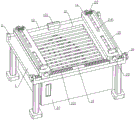
FIG. 1 is a first schematic structural diagram of an embodiment of a high-power laser cutting table according to the present invention;
FIG. 2 is a schematic structural view of a U-shaped seat according to the present invention;
FIG. 3 is a schematic cross-sectional view of the U-shaped seat of the present invention;
FIG. 4 is a schematic structural diagram of a second embodiment of a high-power laser cutting table according to the present invention;
FIG. 5 is a third schematic structural diagram of an embodiment of a high-power laser cutting table according to the present invention;
fig. 6 is a schematic structural view of the filter plate of the present invention.
The device comprises a workbench 1, a hollow groove 10, a fixed seat 11, a slide rod 12, a limiting seat 121, a first rotating shaft 13, a first thread section 131, a U-shaped seat 14, a baffle 15, a first handle 16, a second rotating shaft 2, a second thread section 20, a sliding block 21, a clamping plate 22, a sliding groove 23, a slotted groove 24, a telescopic curtain 241, a second handle 25, a collecting box 3, a fixed plate 31, a filter screen 32, a fan group 33, a filter plate 34, a T-shaped sliding block 341, a vent 35, a collecting box 36 and a sealing box door 37.
Detailed Description
In order that those skilled in the art can better understand the present invention, the following technical solutions are further described with reference to the accompanying drawings and examples.
As shown in fig. 1-6, the high-power laser cutting workbench of the utility model comprises a workbench 1, wherein the workbench 1 is provided with a clamping mechanism, the middle part of the workbench 1 is provided with a hollow groove 10, and the lower side of the hollow groove 10 is provided with a collecting mechanism;
fixture includes two sets of fixing bases 11, slide bar 12, first pivot 13 and two U-shaped seats 14, both sides around workstation 1 are located respectively to two sets of fixing bases 11, the quantity of every group fixing base 11 is two and locates workstation 1's both ends about respectively, slide bar 12 is fixed to be located between two fixing bases 11 that are located the rear side, first pivot 13 rotates the assembly between two fixing bases 11 that are located the front side, the first pivot 13 left and right sides all is equipped with first screw section 131, and the screw of two first screw section 131 revolves to opposite, the one end of two U-shaped seats 14 all with slide bar 12 sliding connection, the other end of two U-shaped seats 14 respectively with two first screw section 131 threaded connection, two U-shaped seat 14 upsides all are fixed and are equipped with baffle 15, U-shaped seat 14 is equipped with fixed subassembly, both ends all run through fixing base 11 and are connected with the first in command 16 about first pivot 13.
The worker can rotate the first handle 16 to drive the first rotating shaft 13 to rotate, because the left side and the right side of the first rotating shaft 13 are provided with the two first threaded sections 131 with opposite thread turning directions, the front side end feet of the two U-shaped seats 14 are respectively in threaded connection with the two first threaded sections 131, and the rear side end feet of the two U-shaped seats 14 are both in sliding connection with the sliding rod 12, when the first rotating shaft 13 rotates, the two U-shaped seats 14 can be driven to move relatively or move oppositely, the sliding rod 12 can limit the U-shaped seats 14 to only move along the direction of the first rotating shaft 13, and the U-shaped seats 14 are more stable when moving, so that when the two U-shaped seats 14 move relatively, some plates with shorter length can be placed, when the two U-shaped seats 14 move oppositely, some plates with longer length can be placed, and the plates are fixed by the fixing components on the U-shaped seats 14, the plates with different sizes can be effectively fixed, the situation that the position of the plate is shifted when the plate is subjected to laser cutting, the quality of a finished product is influenced, and the processing precision is improved;
when the cutting device is used, a worker can rotate the handle 16 in the forward direction to drive the first rotating shaft 13 to rotate in the forward direction, so that the two U-shaped seats 14 move oppositely to a proper distance, then a plate to be cut is placed on the two U-shaped seats 14, then the worker drives the first rotating shaft 13 to rotate in the reverse direction through rotating the handle 16 in the reverse direction, so that the two U-shaped seats 14 move relatively, the left and right directions of the plate are clamped and fixed through the baffle 15 fixed on the upper side of the U-shaped seats 14, finally the front and back directions of the baffle 15 are clamped and fixed through the fixing components on the two U-shaped seats 14, so that the plate is fixed on the workbench 1, the left and right ends of the plate are placed on the two U-shaped seats 14, the bottom of the plate is away from the workbench 1 by a certain distance, the cutting part in the middle of the plate is in a suspended state, and therefore, when laser cutting is carried out, the laser cannot cause damage to the workbench, meanwhile, debris generated during laser cutting falls into the collecting mechanism through the hollow groove 10, and the debris is uniformly collected through the collecting mechanism;
the utility model can carry out omnibearing clamping and fixing on the plates with different sizes through the clamping mechanism, has low use limit, avoids the deviation of the position of the plate when carrying out laser cutting to influence the quality of a finished product and improves the processing precision.
The fixing assembly comprises a second rotating shaft 2, two sliding blocks 21 and two clamping plates 22, the U-shaped seat 14 is provided with a sliding groove 23, the second rotating shaft 2 is rotatably assembled in the sliding groove 23, the front side and the rear side of the second rotating shaft 2 are respectively provided with a second thread section 20, the thread turning directions of the two second thread sections 20 are opposite, the two sliding blocks 21 are respectively assembled in the sliding groove 23 in a sliding manner, the two sliding blocks 21 are respectively in threaded connection with the two second thread sections 20, the two clamping plates 22 are respectively connected with the upper ends of the two sliding blocks 21, the sliding groove 23 is provided with a slot 24 matched with the clamping plates 22, and the two ends of the second rotating shaft 2 are respectively connected with a second handle 25 through the U-shaped seat 14; thus, after the left and right ends of the plate are clamped by the baffles 15 on the two U-shaped seats 14, a worker can rotate the second handle 25 on the U-shaped seat 14, the second handle 25 drives the second rotating shaft 2 to rotate, because the front and back sides of the second rotating shaft 2 are provided with the two second thread sections 20 with opposite thread turning directions, and the two sliding blocks 21 which are assembled in the sliding grooves 23 in a sliding mode are respectively in threaded connection with the two second thread sections 20, the second rotating shaft 2 rotates to drive the two sliding blocks 21 to move relatively or move oppositely, the worker rotates the handle 25 forward to drive the second rotating shaft 2 to rotate forward to drive the two sliding blocks 21 to move relatively, so that the two clamping plates 22 which are respectively connected with the upper ends of the two sliding blocks 21 move relatively, the plate is clamped and fixed in the front and back directions, the plate is stably fixed on the two U-shaped seats 14, and the open grooves 24 can meet the movement stroke of the clamping plates 22, when the fixing of the plate is cancelled, it is only necessary to rotate the second handle 25 in the opposite direction to drive the second rotating shaft 2 to rotate in the opposite direction, so that the two clamping plates 22 move in the opposite direction.
The collecting mechanism comprises a collecting box 3, two fixing plates 31, two filter screens 32 and a fan set 33, the collecting box 3 is arranged at the lower side of the hollow groove 10, the two fixing plates 31 are respectively arranged at the left side and the right side of the bottom of the collecting box 3, the two filter screens 32 are respectively fixed on the two fixing plates 31, the upper ends of the two filter screens 32 are inclined towards the middle and are mutually connected, the fan set 33 is arranged between the two fixing plates 31, the filter plates 34 positioned at the lower side of the fan set 33 are detachably connected between the two fixing plates 31, and the lower side of the collecting box 3 is provided with a vent 35; like this panel is when carrying out laser cutting, the piece that its produced will drop to in the collecting box 3 through fretwork groove 10, the piece will drop to on two filter screens 32, because two filter screen 32 upper ends are connected, the lower extreme is connected with the fixed plate 31 that is located the collecting box 3 left and right sides respectively, so two filter screens 32 are for by the middle part to the slope of both sides from high to low, then the piece can roll to collecting box 3 both sides because of the dead weight, and produce suction through start-up fan group 33, waste gas that produces when cutting the laser inhales in the collecting box 3, then discharge through vent 35, waste gas will pass through filter plate 34 before the discharge, filter waste gas through filter plate 34, make the combustion gas not polluting the air, the effectual staff's of having guaranteed health.
The left side and the right side of the collecting box 3 are both provided with collecting boxes 36, the collecting boxes 36 are positioned between the fixed plate 31 and the side wall of the collecting box 3, and the front side of the collecting box 3 is rotatably connected with a sealing box door 37; the debris can thus fall into the collecting boxes 36 on both sides, and by providing the seal box door 37, uniform processing of the debris in the collecting box 3 can be facilitated.
The filter plate 34 is internally provided with activated carbon, the left side and the right side of the filter plate 34 are both fixed with T-shaped sliding blocks 341, and the two fixing plates 31 are provided with T-shaped sliding chutes matched with the T-shaped sliding blocks 341; like this adsorb through the harmful substance in the active carbon to the waste gas, can make exhaust air cleaner to the filter plate 34 passes through T shape slider 341 and the T shape spout cooperation on the fixed plate 31, can the slidable assembly between two fixed plates 31, when needs clear up filter plate 34, only need open sealed chamber door 37, then outwards take out filter plate 34 can.
The middle part of the sliding rod 12 is provided with a limiting seat 121; therefore, the two U-shaped seats 14 are limited by the limiting seats 121, and the two U-shaped seats 14 are prevented from leaving the first threaded section 131.
The slot 24 is provided with a telescopic curtain 241, and the end part of the telescopic curtain 241 is connected with the clamping plate 22; block slot 24 through flexible curtain 241 like this, avoid impurity to drop to the spout 23 in for spout 23 blocks up, and when splint 22 moved, flexible curtain 241 also can follow splint 22 and move, stretch out and draw back and expand, block the slot all the time.
The foregoing embodiments are merely illustrative of the principles of the present invention and its efficacy, and are not to be construed as limiting the utility model. Any person skilled in the art can modify or change the above-mentioned embodiments without departing from the spirit and scope of the present invention. Accordingly, it is intended that all equivalent modifications or changes which can be made by those skilled in the art without departing from the spirit and technical spirit of the present invention be covered by the claims of the present invention.
Claims (7)
1. A high-power laser cutting workstation which characterized in that: the device comprises a workbench, wherein the workbench is provided with a clamping mechanism, the middle part of the workbench is provided with a hollow groove, and the lower side of the hollow groove is provided with a collecting mechanism;
the clamping mechanism comprises two groups of fixed seats, a sliding rod, a first rotating shaft and two U-shaped seats, the two groups of fixed seats are respectively arranged at the front side and the rear side of the workbench, the number of the fixed seats in each group is two, and the two fixed seats are respectively arranged at the left end and the right end of the workbench, the sliding rod is fixedly arranged between the two fixed seats positioned at the rear side, the first rotating shaft is rotatably assembled between the two fixed seats positioned at the front side, the left side and the right side of the first rotating shaft are both provided with first thread sections, the thread turning directions of the two first thread sections are opposite, one ends of the two U-shaped seats are both connected with the sliding rod in a sliding manner, the other ends of the two U-shaped seats are respectively connected with the two first thread sections in a threaded manner, the upper sides of the two U-shaped seats are both fixedly provided with a baffle plate, the U-shaped seat is provided with a fixing component, and the left end and the right end of the first rotating shaft penetrate through the fixing seat and are connected with a first handle.
2. A high power laser cutting table as claimed in claim 1, wherein: fixed subassembly includes second pivot, two sliders and two splint, the U-shaped seat is equipped with the spout, the second pivot rotates the assembly and is in the spout, both sides all are equipped with the second screw thread section around the second pivot, two the screw thread of second screw thread section revolves to opposite, two the equal sliding fit of slider is in the spout, and two the slider respectively with two second screw thread section threaded connection, two splint respectively with two the slider upper end is connected, the spout be equipped with splint assorted fluting, second pivot both ends all run through the U-shaped seat is connected with the second handle.
3. A high power laser cutting table as claimed in claim 2, wherein: the collecting mechanism comprises a collecting box, two fixing plates, two filter screens and a fan set, wherein the collecting box is arranged on the lower side of the hollow groove, the two fixing plates are respectively arranged on the left side and the right side of the bottom of the collecting box, the two filter screens are respectively fixedly arranged on the two fixing plates, the two filter screens are inclined towards the middle part and are connected with each other, the fan set is arranged between the two fixing plates, the two filter screens are detachably connected between the two fixing plates and are positioned on the filter plates on the lower side of the fan set, and the lower side of the collecting box is provided with a ventilation opening.
4. A high power laser cutting table as claimed in claim 3, wherein: the collecting box is characterized in that collecting boxes are arranged on the left side and the right side of the collecting box and located between the fixed plate and the side wall of the collecting box, and a sealing box door is rotatably connected to the front side of the collecting box.
5. A high power laser cutting table as claimed in claim 3, wherein: the filter plate is internally provided with active carbon, the left side and the right side of the filter plate are both fixed with T-shaped sliding blocks, and the two fixing plates are provided with T-shaped sliding chutes matched with the T-shaped sliding blocks.
6. A high power laser cutting table as claimed in claim 1, wherein: the middle part of the sliding rod is provided with a limiting seat.
7. A high power laser cutting table as claimed in claim 2, wherein: the fluting is equipped with flexible curtain, flexible curtain tip with splint are connected.
Priority Applications (1)
| Application Number | Priority Date | Filing Date | Title |
|---|---|---|---|
| CN202122296594.3U CN215787579U (en) | 2021-09-22 | 2021-09-22 | High-power laser cutting workbench |
Applications Claiming Priority (1)
| Application Number | Priority Date | Filing Date | Title |
|---|---|---|---|
| CN202122296594.3U CN215787579U (en) | 2021-09-22 | 2021-09-22 | High-power laser cutting workbench |
Publications (1)
| Publication Number | Publication Date |
|---|---|
| CN215787579U true CN215787579U (en) | 2022-02-11 |
Family
ID=80165215
Family Applications (1)
| Application Number | Title | Priority Date | Filing Date |
|---|---|---|---|
| CN202122296594.3U Active CN215787579U (en) | 2021-09-22 | 2021-09-22 | High-power laser cutting workbench |
Country Status (1)
| Country | Link |
|---|---|
| CN (1) | CN215787579U (en) |
Cited By (2)
| Publication number | Priority date | Publication date | Assignee | Title |
|---|---|---|---|---|
| CN114850705A (en) * | 2022-05-25 | 2022-08-05 | 深圳市奇彩液晶显示技术有限公司 | Cell-phone screen cutting and collecting device |
| CN116532820A (en) * | 2023-06-30 | 2023-08-04 | 江苏乐萌精密科技有限公司 | Clamp for metal super-thin sheet laser opening |
-
2021
- 2021-09-22 CN CN202122296594.3U patent/CN215787579U/en active Active
Cited By (4)
| Publication number | Priority date | Publication date | Assignee | Title |
|---|---|---|---|---|
| CN114850705A (en) * | 2022-05-25 | 2022-08-05 | 深圳市奇彩液晶显示技术有限公司 | Cell-phone screen cutting and collecting device |
| CN114850705B (en) * | 2022-05-25 | 2024-01-30 | 深圳市奇彩液晶显示技术有限公司 | Mobile phone screen cutting and collecting device |
| CN116532820A (en) * | 2023-06-30 | 2023-08-04 | 江苏乐萌精密科技有限公司 | Clamp for metal super-thin sheet laser opening |
| CN116532820B (en) * | 2023-06-30 | 2023-10-10 | 江苏乐萌精密科技有限公司 | Clamp for metal super-thin sheet laser opening |
Similar Documents
| Publication | Publication Date | Title |
|---|---|---|
| CN210703165U (en) | Laser cutting machine capable of self-cleaning | |
| CN220591915U (en) | A laser cutting machine for processing elevator accessories | |
| CN116262357A (en) | An automatic loading and unloading mechanism and working method for mechanical processing | |
| WO2022262709A1 (en) | Abrasive belt clamp holder used with table-type curve saw and use method therefor | |
| CN212884056U (en) | Dust extraction that welding shop used | |
| CN207914813U (en) | A laser cutting machine with a rotary chuck | |
| CN212682831U (en) | Laser cutting machine with high machining precision | |
| CN218926592U (en) | Laser cutting machine | |
| CN213672440U (en) | Novel laser circular tube cutting machine | |
| CN211072274U (en) | Laser cutting machine | |
| CN205741692U (en) | A kind of novel flash removed cloth inspecting machine | |
| CN214077859U (en) | Metal scrap treatment device for gantry type machining center | |
| CN212918101U (en) | Laser cutting machine that multi-angle was adjusted | |
| CN221910334U (en) | A rotatable laser welding cutting head | |
| CN220278657U (en) | A dust cleaning device for cutting machines | |
| CN211840553U (en) | Novel blade shaping cutting is used in fan processing device | |
| CN211162456U (en) | Energy-saving dust-removing metal cutting machine | |
| CN119159266A (en) | A fiber laser cutting machine | |
| CN214024793U (en) | Novel lathe baffle | |
| CN209831821U (en) | Cutting device with dust absorption function | |
| CN222307709U (en) | Laser cutting machine capable of cleaning debris | |
| CN221676434U (en) | Door handle cutting device | |
| CN222078323U (en) | A bed dust removal device based on large-format laser cutting machine | |
| CN221064863U (en) | Laser cutting device for machining | |
| CN211840763U (en) | Frock clamp for welding |
Legal Events
| Date | Code | Title | Description |
|---|---|---|---|
| GR01 | Patent grant | ||
| GR01 | Patent grant |