CN215782241U - Detachable shell for purifier - Google Patents
Detachable shell for purifier Download PDFInfo
- Publication number
- CN215782241U CN215782241U CN202122143057.5U CN202122143057U CN215782241U CN 215782241 U CN215782241 U CN 215782241U CN 202122143057 U CN202122143057 U CN 202122143057U CN 215782241 U CN215782241 U CN 215782241U
- Authority
- CN
- China
- Prior art keywords
- casing
- fixed connection
- bevel gear
- slide bar
- threaded rod
- Prior art date
- Legal status (The legal status is an assumption and is not a legal conclusion. Google has not performed a legal analysis and makes no representation as to the accuracy of the status listed.)
- Active
Links
- 230000007246 mechanism Effects 0.000 claims abstract description 13
- 238000001914 filtration Methods 0.000 claims description 10
- 230000006978 adaptation Effects 0.000 claims description 5
- 238000009826 distribution Methods 0.000 claims description 2
- 230000008878 coupling Effects 0.000 abstract description 10
- 238000010168 coupling process Methods 0.000 abstract description 10
- 238000005859 coupling reaction Methods 0.000 abstract description 10
- 239000000428 dust Substances 0.000 description 39
- 238000000034 method Methods 0.000 description 5
- 230000008859 change Effects 0.000 description 3
- 238000009434 installation Methods 0.000 description 3
- 230000008569 process Effects 0.000 description 3
- 238000013459 approach Methods 0.000 description 2
- 230000000694 effects Effects 0.000 description 2
- 238000001125 extrusion Methods 0.000 description 2
- 230000006872 improvement Effects 0.000 description 2
- 230000004048 modification Effects 0.000 description 2
- 238000012986 modification Methods 0.000 description 2
- 238000003860 storage Methods 0.000 description 2
- TVEXGJYMHHTVKP-UHFFFAOYSA-N 6-oxabicyclo[3.2.1]oct-3-en-7-one Chemical compound C1C2C(=O)OC1C=CC2 TVEXGJYMHHTVKP-UHFFFAOYSA-N 0.000 description 1
- 241000894006 Bacteria Species 0.000 description 1
- 238000010521 absorption reaction Methods 0.000 description 1
- 238000004891 communication Methods 0.000 description 1
- 238000010276 construction Methods 0.000 description 1
- 238000011161 development Methods 0.000 description 1
- 238000010586 diagram Methods 0.000 description 1
- 230000005611 electricity Effects 0.000 description 1
- 238000003912 environmental pollution Methods 0.000 description 1
- 239000012535 impurity Substances 0.000 description 1
- 238000012423 maintenance Methods 0.000 description 1
- 238000004519 manufacturing process Methods 0.000 description 1
- 230000002035 prolonged effect Effects 0.000 description 1
- 238000000926 separation method Methods 0.000 description 1
Images


Landscapes
- Filtration Of Liquid (AREA)
Abstract
The application discloses clarifier is with dismantling casing, including casing and filter mechanism, PMKD, motor, dwang, threaded rod and the kelly of setting in casing one side, PMKD top fixed connection clarifier, the fixed frame of casing left and right sides fixed connection, filter mechanism includes the filter screen. In order to realize the function of the dismouting of being convenient for, slide the casing on the slide bar, catch the clarifier cover, the output of motor drives the first bevel gear rather than the rigid coupling and rotates after that, first bevel gear drives the second bevel gear rotation of one side meshing, second bevel gear drives the dwang rather than the rigid coupling and rotates, the dwang drives the threaded rod of both sides threaded connection and is close to each other, the stopper that the threaded rod drove the top rigid coupling simultaneously slides on the limiting plate, when the threaded rod drives the kelly joint rather than the rigid coupling and when the jack-up was seted up on the slide bar, accomplish the fixed to the casing, the function of the dismouting of being convenient for has been realized simultaneously.
Description
Technical Field
The application relates to the field of purifiers, in particular to a detachable shell for a purifier.
Background
Along with the development of society, environmental pollution is more and more serious, the harmful gas of production seriously influences our normal life, it is our main activity place in addition indoor, although indoor can the main component PM2.5 of the most haze of separation, but also a small amount of entering is indoor, and indoor be airtight space, long-time activity breeds various bacterium easily, so can use the clarifier to purify the air often, when the clarifier is used for a long time, can lead to being covered with the dust on the clarifier, so generally can cover the clarifier with the casing.
The existing shell for the purifier has simpler structure and function, and most shells cannot be stably arranged on the purifier; in addition, the filter screen on part of the shell is inconvenient to disassemble. Therefore, a detachable housing for a purifier is proposed to solve the above problems.
Disclosure of Invention
The detachable shell for the purifier is provided in the embodiment and used for solving the problem that the filter screen on the shell for the purifier in the prior art is not convenient to replace.
According to one aspect of the application, a detachable shell for a purifier is provided, which comprises a shell, a filtering mechanism, a fixed bottom plate, a motor, a rotating rod, a threaded rod and a clamping rod, wherein the filtering mechanism, the fixed bottom plate, the motor, the rotating rod, the threaded rod and the clamping rod are arranged on one side of the shell, the purifier is fixedly connected to the top of the fixed bottom plate, the fixed frame is fixedly connected to the left side and the right side of the shell, the filtering mechanism comprises a filtering net, the filtering net is slidably connected to the inside of the fixed frame, mounting grooves are formed in the left side and the right side of the shell, sliding blocks are slidably connected to the inside of the mounting grooves, a clamping block is fixedly connected to one side of the sliding block, the clamping block is clamped to one side of the filtering net, the fixed blocks are symmetrically and fixedly connected to the inside of the shell, the rotating rod is connected between the two fixing blocks, the threaded rod is connected to the left side and the threaded rod, the clamping rod is fixedly connected to the other side of the clamping rod, and the slide bar is provided with a clamping hole matched with the clamping rod.
Further, casing bottom fixed connection PMKD, PMKD bottom fixed connection travelling wheel, the quantity of travelling wheel is four, just the even distribution of travelling wheel is four ends at PMKD bottom.
Further, the inside both sides sliding connection slide bar of casing, the slide bar left and right sides fixed connection clarifier, just the inside spout of seting up with the slide bar adaptation of casing, the air exit has been seted up to slide bar one side.
Further, the slider runs through and the sliding connection dead lever, both sides fixed connection mounting groove about the dead lever, the dead lever surface cover is equipped with the spring, spring one side fixed connection slider, spring opposite side fixed connection mounting groove.
Furthermore, the surface of the rotating rod is fixedly connected with a second bevel gear, one side of the second bevel gear is meshed with a first bevel gear, the top of the first bevel gear is fixedly connected with a motor, and the bottom of the motor is fixedly connected with a shell.
Further, one side of the top of the threaded rod is fixedly connected with a limiting block, the other side of the limiting block is slidably connected with a limiting plate, and a limiting groove matched with the limiting block is formed in the limiting plate.
Through the above-mentioned embodiment of this application, adopted filter mechanism, solved the filter screen on the casing for the clarifier problem of being not convenient for change, guaranteed the regulation nature of being convenient for of device simultaneously.
Drawings
In order to more clearly illustrate the embodiments of the present application or the technical solutions in the prior art, the drawings needed to be used in the description of the embodiments or the prior art will be briefly introduced below, and it is obvious that the drawings in the following description are only some embodiments of the present application, and it is obvious for those skilled in the art that other drawings can be obtained according to the drawings without inventive exercise.
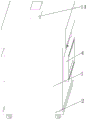
FIG. 1 is a schematic overall perspective view of an embodiment of the present application;
FIG. 2 is a schematic diagram of the overall internal structure of an embodiment of the present application;
fig. 3 is an enlarged schematic view of a structure shown in fig. 2 according to an embodiment of the present disclosure.
In the figure: 1. a housing; 2. fixing the bottom plate; 3. a travel wheel; 4. a fixing frame; 5. a purifier; 6. an air outlet; 7. a filter screen; 8. a slide bar; 9. mounting grooves; 10. fixing the rod; 11. a spring; 12. a slider; 13. a clamping block; 14. an electric motor; 15. a first bevel gear; 16. a second bevel gear; 17. rotating the rod; 18. a fixed block; 19. a clamping rod; 20. a clamping hole; 21. a threaded rod; 22. a limiting plate; 23. and a limiting block.
Detailed Description
In order to make the technical solutions better understood by those skilled in the art, the technical solutions in the embodiments of the present application will be clearly and completely described below with reference to the drawings in the embodiments of the present application, and it is obvious that the described embodiments are only partial embodiments of the present application, but not all embodiments. All other embodiments, which can be derived by a person skilled in the art from the embodiments given herein without making any creative effort, shall fall within the protection scope of the present application.
It should be noted that the terms "first," "second," and the like in the description and claims of this application and in the drawings described above are used for distinguishing between similar elements and not necessarily for describing a particular sequential or chronological order. It should be understood that the data so used may be interchanged under appropriate circumstances such that embodiments of the application described herein may be used. Furthermore, the terms "comprises," "comprising," and "having," and any variations thereof, are intended to cover a non-exclusive inclusion, such that a process, method, system, article, or apparatus that comprises a list of steps or elements is not necessarily limited to those steps or elements expressly listed, but may include other steps or elements not expressly listed or inherent to such process, method, article, or apparatus.
In this application, the terms "upper", "lower", "left", "right", "front", "rear", "top", "bottom", "inner", "outer", "middle", "vertical", "horizontal", "lateral", "longitudinal", and the like indicate orientations or positional relationships based on the orientations or positional relationships shown in the drawings. These terms are used primarily to better describe the present application and its embodiments, and are not used to limit the indicated devices, elements or components to a particular orientation or to be constructed and operated in a particular orientation.
Moreover, some of the above terms may be used to indicate other meanings besides the orientation or positional relationship, for example, the term "on" may also be used to indicate some kind of attachment or connection relationship in some cases. The specific meaning of these terms in this application will be understood by those of ordinary skill in the art as appropriate.
Furthermore, the terms "mounted," "disposed," "provided," "connected," and "sleeved" are to be construed broadly. For example, it may be a fixed connection, a removable connection, or a unitary construction; can be a mechanical connection, or an electrical connection; may be directly connected, or indirectly connected through intervening media, or may be in internal communication between two devices, elements or components. The specific meaning of the above terms in the present application can be understood by those of ordinary skill in the art as appropriate.
It should be noted that the embodiments and features of the embodiments in the present application may be combined with each other without conflict. The present application will be described in detail below with reference to the embodiments with reference to the attached drawings.
The filter mechanism in this embodiment may be applied to a computer case, for example, in this embodiment, a dust removing device for a computer case is provided, and the filter mechanism in this embodiment may be used to filter dust of the computer case.
A dust removal device for a computer case comprises a dust remover main body, a dust collection bin, a sucker and a dust removal disc, wherein an operation button is arranged on the upper surface of the dust remover main body, the dust collection bin is arranged at the middle position inside the dust remover main body, a cover plate is arranged on one side of the dust collection bin through a hinge, a pull block is arranged on the cover plate and is convenient to replace and install a filter screen, the filter screen is vertically arranged on one side, close to a dust collection pump, inside the dust collection bin and used for preventing overlarge impurities from entering the dust collection pump and causing damage to the dust collection pump, sliding blocks are arranged at two ends of the filter screen, sliding rails matched with the sliding blocks are arranged on two sides of the inner wall of the dust collection bin and used for pulling and pulling the filter screen, the filter screen is convenient to install, a first cavity is arranged inside the dust remover main body on the left side of the dust collection bin, a dust collection pump is arranged at the bottom of the first cavity, a first dust collection pipe is arranged at the output end of the dust collection pump, and is connected with the dust collection bin, a second dust suction pipe is installed on the right side of the dust collection bin, one end, far away from the dust collection bin, of the second dust suction pipe extends to the outer surface of the dust collector main body, a sucker is installed at one end, far away from the dust collector main body, of the second dust suction pipe, a second cavity is installed inside the dust collector main body on the left side of the first cavity, a storage battery is installed inside the second cavity, the output end of an operation button is electrically connected with the input end of the storage battery through a wire, a shell is installed on the inner wall of the dust collector main body above the second dust suction pipe, a motor is installed inside the shell, a driving shaft is vertically installed at the output end of the motor and penetrates through the dust collector main body, a driving wheel is installed on the driving shaft, a mounting frame is installed on the surface of the dust collector main body right above the motor, a driven shaft is vertically installed at the bottom of the mounting frame on one side of the driving wheel, a driven wheel is installed on the driven wheel, and the driven wheel is connected with the driving wheel through a belt, the dust removal dish is all installed to the top of driving shaft and driven shaft, the fixture block is all installed on the top of driving shaft and driven shaft, the fixed block is all installed to the bottom of dust removal dish, the draw-in groove is all installed to the fixed block bottom, the inner wall of draw-in groove is provided with the internal thread, the surface of fixture block is provided with the external screw thread of mutually supporting with the internal thread, make dust removal dish demountable installation, convenient to use person dismantles the dust removal dish, the work of replacement and maintenance, the life of the device is prolonged, the output of battery passes through the wire respectively with the dust absorption pump, the motor electricity is connected.
Of course, the filter mechanism of the present embodiment may be applied to a case for a purifier. The details of the purifier housing according to the embodiment of the present application will not be described below.
Referring to fig. 1-3, a detachable shell for a purifier comprises a shell 1, and a filtering mechanism, a fixing bottom plate 2, a motor 14, a rotating rod 17, a threaded rod 21 and a clamping rod 19 which are arranged on one side of the shell 1, wherein the top of the fixing bottom plate 2 is fixedly connected with the purifier 5, the left side and the right side of the shell 1 are fixedly connected with a fixing frame 4, the filtering mechanism comprises a filter screen 7, the filter screen 7 is slidably connected with the inside of the fixing frame 4, the left side and the right side of the shell 1 are provided with mounting grooves 9, the inside of the mounting grooves 9 is slidably connected with a sliding block 12, one side of the sliding block 12 is fixedly connected with a clamping block 13, the clamping block 13 is clamped with one side of the filter screen 7, the inside of the shell 1 is symmetrically and fixedly connected with fixing blocks 18, the rotating rod 17 is rotatably connected between the two fixing blocks 18, the left side and the right side of the rotating rod 17 are in threaded connection with the threaded rod 21, the other side of the threaded rod 21 is fixedly connected with the clamping rod 19, one side of the clamping rod 19 is clamped with the sliding rod 8, and a clamping hole 20 matched with the clamping rod 19 is formed in the sliding rod 8.
The bottom of the shell 1 is fixedly connected with a fixed bottom plate 2, the bottom of the fixed bottom plate 2 is fixedly connected with four traveling wheels 3, and the four traveling wheels 3 are uniformly distributed at four ends of the bottom of the fixed bottom plate 2; two sides inside the shell 1 are connected with sliding rods 8 in a sliding manner, the left side and the right side of each sliding rod 8 are fixedly connected with purifiers 5, a sliding groove matched with each sliding rod 8 is formed inside the shell 1, and an air outlet 6 is formed in one side of each sliding rod 8; the sliding block 12 penetrates through and is connected with a fixed rod 10 in a sliding mode, the upper side and the lower side of the fixed rod 10 are fixedly connected with installation grooves 9, a spring 11 is sleeved on the surface of the fixed rod 10, one side of the spring 11 is fixedly connected with the sliding block 12, and the other side of the spring 11 is fixedly connected with the installation grooves 9; the surface of the rotating rod 17 is fixedly connected with a second bevel gear 16, one side of the second bevel gear 16 is meshed and connected with a first bevel gear 15, the top of the first bevel gear 15 is fixedly connected with a motor 14, and the bottom of the motor 14 is fixedly connected with the shell 1; the threaded rod 21 top one side fixed connection stopper 23, stopper 23 opposite side sliding connection limiting plate 22, limiting plate 22 is inside to be seted up with the spacing groove of stopper 23 adaptation.
When the purifier is used, electrical components in the application are externally connected with a power supply and a control switch, firstly, the shell 1 slides on the sliding rod 8, the purifier 5 is sleeved, then the motor 14 is started, the output end of the motor 14 drives the first bevel gear 15 fixedly connected with the motor to rotate, the first bevel gear 15 drives the second bevel gear 16 meshed with one side to rotate, the second bevel gear 16 drives the rotating rod 17 fixedly connected with the rotating rod to rotate, the rotating rod 17 drives the threaded rods 21 in threaded connection at two sides to approach each other, meanwhile, the threaded rods 21 drive the limiting blocks 23 fixedly connected with the top to slide on the limiting plates 22, when the threaded rods 21 drive the clamping rods 19 fixedly connected with the threaded rods to be clamped in the clamping holes 20 formed in the sliding rod 8, the shell 1 is fixed, and meanwhile, the function of facilitating disassembly and assembly is realized; when filter screen 7 needs to be changed, to both sides pulling handle, the handle drives the slider 12 rather than the rigid coupling and removes to both sides, slider 12 drives the fixture block 13 of one side rigid coupling and slides on dead lever 10 simultaneously, 12 extrusion of slider and the spring 11 of its rigid coupling simultaneously, spring 11 atress shrink, when fixture block 13 breaks away from the joint relation with filter screen 7, outside pulling filter screen 7, be convenient for give filter screen 7 and take out, when installing filter screen 7, loosen the handle, spring 11 resets and drives fixture block 13 joint in filter screen 7 one side through slider 12, the completion is to filter screen 7's change, the rationality of structure has been embodied.
The application has the advantages that:
1. in order to realize the function of convenient disassembly and assembly, the shell slides on the slide bar, the purifier is sleeved and connected, then the output end of the motor drives the first bevel gear fixedly connected with the motor to rotate, the first bevel gear drives the second bevel gear meshed with one side to rotate, the second bevel gear drives the rotating rod fixedly connected with the second bevel gear to rotate, the rotating rod drives the threaded rods in threaded connection at two sides to mutually approach, meanwhile, the threaded rods drive the limiting blocks fixedly connected with the top to slide on the limiting plates, when the threaded rods drive the clamping rods fixedly connected with the threaded rods to be clamped in the clamping holes formed in the slide bar, the fixation of the shell is finished, and the function of convenient disassembly and assembly is realized;
2. this application is rational in infrastructure, when the filter screen needs to be changed, to both sides pulling handle, the handle drives the slider rather than the rigid coupling and removes to both sides, the slider drives the fixture block of one side rigid coupling and slides on the dead lever simultaneously, the slider extrusion simultaneously and the spring of its rigid coupling, the spring atress shrink, when the fixture block breaks away from the joint relation with the filter screen, to the outside pulling filter screen, be convenient for give the filter screen and take out, when installing the filter screen, loosen the handle, the spring resets and drives the fixture block joint in filter screen one side through the slider, the completion is to the change of filter screen, the rationality of structure has been embodied.
It is well within the skill of those in the art to implement, without undue experimentation, the present application is not directed to software and process improvements, as they relate to circuits and electronic components and modules.
The above description is only a preferred embodiment of the present application and is not intended to limit the present application, and various modifications and changes may be made by those skilled in the art. Any modification, equivalent replacement, improvement and the like made within the spirit and principle of the present application shall be included in the protection scope of the present application.
Claims (6)
1. The utility model provides a clarifier is with dismantling casing which characterized in that: including casing (1) and set up filtering mechanism, PMKD (2), motor (14), dwang (17), threaded rod (21) and kelly (19) in casing (1) one side, PMKD (2) top fixed connection clarifier (5), the fixed frame (4) of casing (1) left and right sides fixed connection, filtering mechanism includes filter screen (7), inside sliding connection filter screen (7) of fixed frame (4), mounting groove (9) have been seted up to the casing (1) left and right sides, inside sliding connection slider (12) of mounting groove (9), slider (12) one side fixed connection fixture block (13), fixture block (13) and filter screen (7) one side looks joint, casing (1) inside symmetry fixed connection fixed block (18), two dwang (17) are connected in the rotation between fixed block (18), dwang (17) left and right sides threaded connection threaded rod (21), threaded rod (21) opposite side fixed connection kelly (19), kelly (19) one side and slide bar (8) joint mutually, just offer card hole (20) with kelly (19) adaptation on slide bar (8).
2. A removable housing for a purifier according to claim 1, wherein: casing (1) bottom fixed connection PMKD (2), PMKD (2) bottom fixed connection travelling wheel (3), the quantity of travelling wheel (3) is four, just the even distribution of travelling wheel (3) is four ends in PMKD (2) bottom.
3. A removable housing for a purifier according to claim 1, wherein: casing (1) inside both sides sliding connection slide bar (8), slide bar (8) left and right sides fixed connection clarifier (5), just casing (1) inside offer with the spout of slide bar (8) adaptation, air exit (6) have been seted up to slide bar (8) one side.
4. A removable housing for a purifier according to claim 1, wherein: slider (12) run through and sliding connection dead lever (10), both sides fixed connection mounting groove (9) about dead lever (10), dead lever (10) surface cover is equipped with spring (11), spring (11) one side fixed connection slider (12), spring (11) opposite side fixed connection mounting groove (9).
5. A removable housing for a purifier according to claim 1, wherein: dwang (17) fixed surface connects second bevel gear (16), first bevel gear (15) is connected in second bevel gear (16) one side meshing, first bevel gear (15) top fixed connection motor (14), motor (14) bottom fixed connection casing (1).
6. A removable housing for a purifier according to claim 1, wherein: threaded rod (21) top one side fixed connection stopper (23), stopper (23) opposite side sliding connection limiting plate (22), limiting plate (22) inside offer with the spacing groove of stopper (23) adaptation.
Priority Applications (1)
| Application Number | Priority Date | Filing Date | Title |
|---|---|---|---|
| CN202122143057.5U CN215782241U (en) | 2021-09-06 | 2021-09-06 | Detachable shell for purifier |
Applications Claiming Priority (1)
| Application Number | Priority Date | Filing Date | Title |
|---|---|---|---|
| CN202122143057.5U CN215782241U (en) | 2021-09-06 | 2021-09-06 | Detachable shell for purifier |
Publications (1)
| Publication Number | Publication Date |
|---|---|
| CN215782241U true CN215782241U (en) | 2022-02-11 |
Family
ID=80156650
Family Applications (1)
| Application Number | Title | Priority Date | Filing Date |
|---|---|---|---|
| CN202122143057.5U Active CN215782241U (en) | 2021-09-06 | 2021-09-06 | Detachable shell for purifier |
Country Status (1)
| Country | Link |
|---|---|
| CN (1) | CN215782241U (en) |
-
2021
- 2021-09-06 CN CN202122143057.5U patent/CN215782241U/en active Active
Similar Documents
| Publication | Publication Date | Title |
|---|---|---|
| CN211663217U (en) | Automobile chassis cleaning device | |
| CN112165814B (en) | Automatic dust removal network rack of dust-protection type | |
| CN219912504U (en) | Automatic remote monitoring device for power grid | |
| CN217855209U (en) | Energy-saving environment-friendly air exhaust purification device convenient for replacing filter plate in factory | |
| CN216204112U (en) | DOP liquid groove type efficient air supply outlet | |
| CN219349479U (en) | Air-cooled external heat dissipation structure | |
| CN212700958U (en) | High-efficient dust collector is used to coal dust | |
| CN218558837U (en) | Fresh air precooling device convenient to dismantle filter screen | |
| CN212998980U (en) | Stainless steel baffle air cleaner | |
| CN220600100U (en) | Filter core is taken out and is inserted formula fan filter | |
| CN220609578U (en) | A waterless dust treatment device | |
| CN215185259U (en) | Anti-harmonic intelligent low-voltage reactive compensation integrated device | |
| CN215962647U (en) | Purification and dust removal device for environmental engineering | |
| CN215841975U (en) | Industrial sewage treatment tank convenient to move | |
| CN216232387U (en) | Material transportation device for building engineering | |
| CN218068753U (en) | Electrical equipment for cooling host | |
| CN220507124U (en) | Air circulation purifying device with filter screen easy to detach | |
| CN223967518U (en) | Protective structure of direct current screen | |
| CN216500023U (en) | Sheet metal machine case with double-layer dustproof function | |
| CN220532563U (en) | Automatic dust removing device for cement production | |
| CN216062408U (en) | Cloth bag type pulse dust removal device | |
| CN221536056U (en) | Communication computer lab ventilation unit convenient to clearance filtration | |
| CN221178093U (en) | Cleaning device of integrated communication collector | |
| CN215094256U (en) | Dust collector is used in timber moulding production | |
| CN213460522U (en) | Switch board dust collector |
Legal Events
| Date | Code | Title | Description |
|---|---|---|---|
| GR01 | Patent grant | ||
| GR01 | Patent grant |