CN215757293U - Microbial fermentation jar agitating unit - Google Patents
Microbial fermentation jar agitating unit Download PDFInfo
- Publication number
- CN215757293U CN215757293U CN202122084366.XU CN202122084366U CN215757293U CN 215757293 U CN215757293 U CN 215757293U CN 202122084366 U CN202122084366 U CN 202122084366U CN 215757293 U CN215757293 U CN 215757293U
- Authority
- CN
- China
- Prior art keywords
- fermentation tank
- stirring shaft
- aeration
- stirring
- aeration disc
- Prior art date
- Legal status (The legal status is an assumption and is not a legal conclusion. Google has not performed a legal analysis and makes no representation as to the accuracy of the status listed.)
- Expired - Fee Related
Links
- 238000000855 fermentation Methods 0.000 title claims abstract description 77
- 230000004151 fermentation Effects 0.000 title claims abstract description 77
- 230000000813 microbial effect Effects 0.000 title claims abstract description 19
- 238000003756 stirring Methods 0.000 claims abstract description 95
- 238000005273 aeration Methods 0.000 claims abstract description 81
- 239000000126 substance Substances 0.000 claims abstract description 13
- 238000007790 scraping Methods 0.000 claims abstract description 10
- 230000005540 biological transmission Effects 0.000 claims description 14
- 230000000712 assembly Effects 0.000 claims description 7
- 238000000429 assembly Methods 0.000 claims description 7
- 230000000149 penetrating effect Effects 0.000 claims description 6
- 238000013019 agitation Methods 0.000 claims description 2
- 235000015097 nutrients Nutrition 0.000 abstract description 3
- 239000007789 gas Substances 0.000 description 34
- CURLTUGMZLYLDI-UHFFFAOYSA-N Carbon dioxide Chemical compound O=C=O CURLTUGMZLYLDI-UHFFFAOYSA-N 0.000 description 6
- QVGXLLKOCUKJST-UHFFFAOYSA-N atomic oxygen Chemical compound [O] QVGXLLKOCUKJST-UHFFFAOYSA-N 0.000 description 5
- 244000005700 microbiome Species 0.000 description 5
- 229910052760 oxygen Inorganic materials 0.000 description 5
- 239000001301 oxygen Substances 0.000 description 5
- 238000009434 installation Methods 0.000 description 4
- 229910002092 carbon dioxide Inorganic materials 0.000 description 3
- 239000001569 carbon dioxide Substances 0.000 description 3
- 241000894006 Bacteria Species 0.000 description 2
- 102000004190 Enzymes Human genes 0.000 description 1
- 108090000790 Enzymes Proteins 0.000 description 1
- 240000004808 Saccharomyces cerevisiae Species 0.000 description 1
- 239000000853 adhesive Substances 0.000 description 1
- 230000001070 adhesive effect Effects 0.000 description 1
- 238000005276 aerator Methods 0.000 description 1
- 238000010564 aerobic fermentation Methods 0.000 description 1
- 230000009286 beneficial effect Effects 0.000 description 1
- 238000006243 chemical reaction Methods 0.000 description 1
- 238000004140 cleaning Methods 0.000 description 1
- 238000007599 discharging Methods 0.000 description 1
- 238000005516 engineering process Methods 0.000 description 1
- 235000013305 food Nutrition 0.000 description 1
- 238000004519 manufacturing process Methods 0.000 description 1
- 239000000463 material Substances 0.000 description 1
- 238000000034 method Methods 0.000 description 1
- 238000012986 modification Methods 0.000 description 1
- 230000004048 modification Effects 0.000 description 1
- 238000006213 oxygenation reaction Methods 0.000 description 1
- 230000001737 promoting effect Effects 0.000 description 1
- 102000004169 proteins and genes Human genes 0.000 description 1
- 108090000623 proteins and genes Proteins 0.000 description 1
- 238000006467 substitution reaction Methods 0.000 description 1
Images




Landscapes
- Apparatus Associated With Microorganisms And Enzymes (AREA)
Abstract
The utility model relates to a stirring device of a microbial fermentation tank, which comprises: the stirring shaft is rotationally arranged in the fermentation tank body, the aeration disc component is arranged on the fermentation tank bottom plate, two groups of tank wall scraper components are symmetrically arranged on the stirring shaft, and a plurality of stirring paddles are uniformly arranged on each tank wall scraper component; the lower end of the stirring shaft is provided with a stirring shaft positioning groove, and the aeration disc component comprises a stirring shaft positioning boss corresponding to the stirring shaft positioning groove and used for supporting and positioning the stirring shaft; the outline of each tank wall scraper component is matched with the outline of the cross section of the cavity between the tank body of the fermentation tank and the stirring shaft, and the tank wall scraper components are used for scraping substances bonded on the inner wall of the fermentation tank. Provides a stirring device of a microbial fermentation tank, which can add gas nutrients into the fermentation tank and can scrape off bonding substances attached to the tank wall in the fermentation process.
Description
Technical Field
The utility model relates to the technical field of microbial fermentation tank devices, in particular to a stirring device of a microbial fermentation tank.
Background
A microbial fermentation tank is a process test instrument used in the field of agriculture, and the fermentation tank is a device for carrying out microbial fermentation and can improve the fermentation efficiency by optimizing the fermentation conditions of microorganisms. The fermentation tank can be classified into an aerobic type and an anaerobic type according to aerobic and anaerobic properties of the cultured microorganism. For an aerobic fermentation tank, microorganisms can generate a large amount of carbon dioxide during fermentation, and the carbon dioxide is precipitated below oxygen due to the fact that the density of the carbon dioxide is greater than that of the oxygen, so that the microorganisms cannot contact with the oxygen and die a large amount of microorganisms, and therefore an oxygenation device needs to be additionally arranged at the bottom of the fermentation tank, and the oxygen is dissolved in the culture solution through stirring of a stirring paddle.
The fermentation tank is a device system which provides a suitable reaction environment for living cells or enzymes to proliferate or produce the cells, and also provides a suitable growth environment for the growth and the reproduction of bacteria to promote the bacteria to produce products required by people. However, in actual production, various foods and the like produce a large amount of protein, yeast and the like, and when the fermentation tank is cleaned, the substances are attached to the wall of the fermentation tank, so that the product quality is seriously affected.
SUMMERY OF THE UTILITY MODEL
The technical problem to be solved by the utility model is to provide a stirring device of a microbial fermentation tank, which can add gas nutrients into the fermentation tank and can scrape off bonding substances attached to the tank wall in the fermentation process, so as to solve the problems in the background technology.
In order to solve the problems, the technical scheme adopted by the utility model is as follows:
a microbial fermentation tank agitation apparatus, comprising: the stirring shaft is rotationally arranged in the fermentation tank body, the aeration disc component is arranged on the fermentation tank bottom plate, two groups of tank wall scraper components are symmetrically arranged on the stirring shaft, and a plurality of stirring paddles are uniformly arranged on each tank wall scraper component;
the lower end of the stirring shaft is provided with a stirring shaft positioning groove, and the aeration disc component comprises a stirring shaft positioning boss corresponding to the stirring shaft positioning groove and used for supporting and positioning the stirring shaft;
the outline of each tank wall scraper component is matched with the outline of the cross section of the cavity between the tank body of the fermentation tank and the stirring shaft, and the tank wall scraper components are used for scraping substances bonded on the inner wall of the fermentation tank.
As a further improvement of the utility model, each tank wall scraper component comprises a scraper framework, two groups of stirring paddle mounting rods and a brush component;
the scraper plate frame comprises a frame top rod connected with the upper part of the stirring shaft and a frame bottom rod connected with the lower part of the stirring shaft, and a frame vertical rod is arranged between the frame top rod and the frame bottom rod;
two groups of stirring paddle mounting rods are arranged between the frame upright rod and the stirring shaft at intervals and used for mounting the stirring paddles;
the brush assembly is uniformly paved on one surface of the frame vertical rod, which faces to the inner wall of the fermentation tank, and is used for scraping off substances adhered to the inner wall of the fermentation tank.
As a further improvement of the utility model, the shape of the frame bottom rod is matched with the outline shape of the aeration disc assembly, and the lower surface of the frame bottom rod is uniformly paved with the brush assembly for scraping substances bonded on the aeration disc assembly.
As a further improvement of the present invention, the aeration tray assembly comprises:
the aeration disc fixing seat is used for penetrating through a bolt assembly to be fixed on the bottom plate of the fermentation tank;
the aeration disc body is fixedly arranged on the aeration disc fixing seat, and a plurality of circles of aeration rings are concentrically arranged on the aeration disc body and used for conveying gas into the fermentation tank;
the gas transmission connector is fixedly arranged below the aeration disc fixing seat, is connected with the aeration disc body and is used for connecting an external gas path so as to transmit gas into the aeration disc body;
and the air supply channels are embedded in the air supply connector and the aeration disc body and are connected with the aeration rings.
As a further improvement of the utility model, the gas transmission connector comprises a gas transmission connecting pipe connected with the aeration disc body and a connecting flange plate sleeved at the lower end of the gas transmission connecting pipe, and the connecting flange plate is used for connecting with the external gas circuit by passing through a bolt.
As a further improvement of the utility model, the gas conveying connector is arranged below the circle center of a plurality of aeration rings, four gas supply channels are arranged in the gas conveying connector, the four gas supply channels are uniformly arranged in the aeration disc body in a radial shape, and each gas supply channel is communicated with each aeration ring.
As a further improvement of the utility model, the upper part of each aeration ring is provided with a plurality of aeration through holes along the circumferential direction of each aeration ring.
As a further improvement of the utility model, the stirring shaft driving device is arranged on the top cover of the fermentation tank, and the stirring shaft upwards penetrates through the top cover of the fermentation tank and is connected with the stirring shaft driving device.
Adopt the produced beneficial effect of above-mentioned technical scheme to lie in:
1. the utility model provides a be provided with the appearance profile on the (mixing) shaft with the profile assorted jar wall scraper blade subassembly of the cavity cross-section between the fermentation cylinder jar body and the (mixing) shaft, jar wall scraper blade subassembly scrapes the bonding material of fermentation cylinder inner wall and bottom through the brush subassembly when rotatory along with the (mixing) shaft, and the effectual residue that adheres the thing that has reduced on the fermentation cylinder inner wall for the clearance efficiency to the fermentation cylinder later stage improves.
2. This application is provided with aeration dish subassembly on fermentation tank bottom plate, can add gas (like oxygen) to the jar in fermentation process, and the cooperation sets up the stirring rake between frame pole setting and (mixing) shaft, is gaseous dissolved in jar interior culture solution, has realized the interpolation to jar interior gas nutrient.
3. This application is for making the stable drive of (mixing) shaft ability jar wall scraper blade subassembly is rotatory, has seted up the (mixing) shaft constant head tank bottom the (mixing) shaft, and aeration dish subassembly is including the (mixing) shaft location boss that corresponds the (mixing) shaft constant head tank setting, and both cooperate and make the (mixing) shaft rotation type can be fixed a position steadily on the aeration dish subassembly.
Drawings
In order to more clearly illustrate the embodiments of the present invention or the technical solutions in the prior art, the drawings used in the description of the embodiments or the prior art will be briefly described below, and it is obvious that the drawings in the following description are some embodiments of the present invention, and other drawings can be obtained by those skilled in the art without creative efforts.
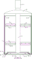
FIG. 1 is a schematic perspective view of an embodiment in a half-concealed fermenter vessel.
Fig. 2 is a perspective view of fig. 1 from another angle.
Fig. 3 is a front view of fig. 1.
Figure 4 is a schematic view of an aeration disc assembly of an embodiment.
Figure 5 is an exploded schematic view of an aerator disk assembly and agitator shaft of an embodiment.
Fig. 6 is an enlarged schematic view at a in fig. 4.
Fig. 7 is an enlarged schematic view at B in fig. 3.
Wherein: 1, fermenting tank body; 1-1 fermenting tank bottom plate;
2, covering the top cover of the fermentation tank;
3, stirring the shaft; 3-1, a stirring shaft driving device; 3-2, positioning a groove on the stirring shaft;
4 a tank wall scraper assembly; 4-0 scraper frame; 4-01 frame ejector rod; 4-02 frame upright stanchions; 4-03 framework bottom bar; 4-1, a stirring paddle mounting rod; 4-2 brush assembly;
5, a stirring paddle;
6 aeration disc assembly; 6-1 a gas transmission connector; 6-2 air supply channels; 6-3, positioning a boss of the stirring shaft; 6-4 aeration ring; 6-5 aeration disc fixing seats; 6-6 of an aeration disc body; 6-41 aeration through holes.
Detailed Description
For the purposes of promoting a clear and complete description of the utility model, and for purposes of making apparent and enabling the utility model to be embodied and broadly described, reference will now be made to the following description of certain embodiments, wherein the terms "center", "vertical", "lateral", "up", "down", "front", "back", "left", "right", "vertical", "horizontal", "top", "bottom", "inner", "outer", and the like are used in the orientation and positional relationship indicated in the drawings, which are for convenience in describing the utility model and simplifying the description, and are not intended to indicate or imply that the device or element so referred to must have a particular orientation, be constructed and operated in a particular orientation, and thus should not be construed as limiting the utility model.
The specific embodiment is as follows:
a microbial fermentation tank stirring device as shown in fig. 1 to 7, comprising: the stirring shaft 3 is rotationally arranged in the fermentation tank body 1, the aeration disc assemblies 6 are arranged on the fermentation tank bottom plate 1-1, the two groups of tank wall scraper assemblies 4 are symmetrically arranged on the stirring shaft 3, and the two groups of stirring paddles 5 are uniformly arranged on each tank wall scraper assembly 4.
As shown in fig. 1 to fig. 3, the stirring apparatus of this embodiment further includes a stirring shaft driving device 3-1 disposed on the fermentation tank top cover 2, the stirring shaft 3 upwardly penetrates through the fermentation tank top cover 2 to be connected with the stirring shaft driving device 3-1, and the fermentation tank top cover 2 is fastened and fixed on the fermentation tank body 1 through a box buckle assembly.
As shown in fig. 5, a stirring shaft positioning groove 3-2 is provided at the lower end of the stirring shaft 3, the aeration disc assembly 6 includes a stirring shaft positioning boss 6-3 corresponding to the stirring shaft positioning groove 3-2 for the stirring shaft 3 to rotate to support and position, and preferably, a plurality of balls are uniformly provided on the surface of the stirring shaft positioning boss 6-3 or the surface of the stirring shaft positioning groove 3-2 in the circumferential direction for reducing the friction between the stirring shaft positioning groove 3-2 and the stirring shaft positioning boss 6-3 (the balls are provided on the stirring shaft positioning boss 6-3 in fig. 4).
As shown in figure 3, the outline of each tank wall scraper component 4 is matched with the outline of the cavity section between the fermentation tank body 1 and the stirring shaft 3, and is used for scraping off substances adhered to the inner wall of the fermentation tank. Each tank wall scraper component 4 comprises a scraper framework 4-0, two groups of stirring paddle mounting rods 4-1 and a brush component 4-2. The scraper frame 4-0 comprises a frame top rod 4-01 connected with the upper part of the stirring shaft 3 and a frame bottom rod 4-03 connected with the lower part of the stirring shaft 3, and a frame vertical rod 4-02 is arranged between the frame top rod 4-01 and the frame bottom rod 4-03;
as shown in fig. 5, two groups of stirring paddle installation rods 4-1 are arranged between the frame upright rod 4-02 and the stirring shaft 3 at intervals, rectangular strip through holes are obliquely arranged on the stirring paddle installation rods 4-1, the shapes and the sizes of the strip through holes are matched with the shapes and the sizes of the sections of the stirring paddles 5 in rectangular plate shapes, bolt through holes are oppositely formed in the stirring paddles 5 and the stirring paddle installation rods 4-1, and when the stirring paddles 5 are installed in place, bolt assemblies are arranged in a penetrating mode to enable the stirring paddles 5 to be fixedly connected with the stirring paddle installation rods 4-1.
As shown in figures 3 and 7, the brush assembly 4-2 is uniformly paved on one side of the frame upright stanchion 4-02 facing the inner wall of the fermentation tank and is used for scraping off substances adhered on the inner wall of the fermentation tank. The shape of the frame bottom rod 4-03 is matched with the profile shape of the section of the fermentation tank bottom plate 1-1 on which the aeration disc assembly 6 is placed, and the brush assemblies 4-2 are uniformly paved on the lower surface of the frame bottom rod 4-03 and used for scraping substances bonded on the aeration disc assembly 6. Because no large adhesive is attached to the inner wall of the fermentation tank, the cleaning is easier and more effective.
As shown in fig. 3 to 5, the aeration tray assembly 6 includes: a disc-shaped aeration disc fixing seat 6-5 which is fixed on the circle center of the fermentation tank bottom plate 1-1 after penetrating through the bolt assembly;
a disc-shaped aeration disc body 6-6 which is concentrically and fixedly arranged on the aeration disc fixing seat 6-5, and is concentrically provided with a plurality of circles of aeration rings 6-4, as shown in figure 6, the upper part of each aeration ring 6-4 is provided with a plurality of aeration through holes 6-41 along the circumferential direction of each aeration ring 6-4 and used for conveying gas into the fermentation tank;
a gas transmission connector 6-1 which is fixedly arranged below the aeration disc fixing seat 6-5 and is connected with the aeration disc body 6-6, used for connecting an external gas circuit to convey gas into the aeration disc body 6-6, the gas conveying connector 6-1 comprises a gas conveying connecting pipe connected with the aeration disc body 6-6 and a connecting flange plate sleeved at the lower end of the gas conveying connecting pipe, the connecting flange plate is used for connecting with the external gas circuit by penetrating bolts, the gas transmission connecting pipe and the fermentation tank bottom plate 1-1 are sealed, when the aeration disc assembly 6 needs to be cleaned and replaced, the connecting flange plate is firstly detached from the gas transmission connecting pipe (6-1 shown in figure 2), then the bolt assembly on the aeration disc fixing seat 6-5 is unscrewed, and the aeration disc assembly is taken out from the upper part;
four air supply channels 6-2 are embedded in the air supply connector 6-1 and the aeration disc body 6-6 and are connected with a plurality of aeration rings 6-4. In this embodiment, the gas delivery connector 6-1 is disposed below the center of the plurality of aeration rings 6-4, and four gas supply channels 6-2 are disposed therein, the four gas supply channels 6-2 are uniformly disposed in the aeration disc body 6-6 in a radial manner, and each gas supply channel 6-2 is communicated with each aeration ring 6-4, and is used for introducing gas delivered from an external gas path into each aeration ring 6-4 and discharging the gas through the plurality of aeration through holes 6-41.
Finally, it should be noted that: the above examples are only intended to illustrate the technical solution of the present invention, but not to limit it; although the present invention has been described in detail with reference to the foregoing embodiments, it will be understood by those of ordinary skill in the art that: the technical solutions described in the foregoing embodiments may still be modified, or some technical features may be equivalently replaced; and such modifications or substitutions do not depart from the spirit and scope of the corresponding technical solutions of the embodiments of the present invention.
Claims (8)
1. The utility model provides a microbial fermentation jar agitating unit which characterized in that, it includes: the fermentation tank comprises a stirring shaft (3) rotatably arranged in a fermentation tank body (1), an aeration disc assembly (6) arranged on a fermentation tank bottom plate (1-1), two groups of tank wall scraper assemblies (4) symmetrically arranged on the stirring shaft (3) and a plurality of stirring paddles (5) uniformly arranged on each tank wall scraper assembly (4);
the lower end of the stirring shaft (3) is provided with a stirring shaft positioning groove (3-2), and the aeration disc assembly (6) comprises a stirring shaft positioning boss (6-3) corresponding to the stirring shaft positioning groove (3-2) and used for supporting and positioning the stirring shaft (3);
the outline of each tank wall scraper component (4) is matched with the outline of the cross section of the cavity between the fermentation tank body (1) and the stirring shaft (3) and is used for scraping substances bonded on the inner wall of the fermentation tank.
2. The microbial fermentation tank stirring device of claim 1, wherein: each tank wall scraper component (4) comprises a scraper framework (4-0), two groups of stirring paddle mounting rods (4-1) and a brush component (4-2);
the scraper framework (4-0) comprises a framework ejector rod (4-01) connected with the upper part of the stirring shaft (3) and a framework bottom rod (4-03) connected with the lower part of the stirring shaft (3), and a framework upright rod (4-02) is arranged between the framework ejector rod (4-01) and the framework bottom rod (4-03);
two groups of stirring paddle mounting rods (4-1) are arranged between the frame upright stanchions (4-02) and the stirring shaft (3) at intervals and used for mounting the stirring paddles (5);
the brush assemblies (4-2) are uniformly paved on one surfaces, facing the inner wall of the fermentation tank, of the frame vertical rods (4-02) and used for scraping off substances bonded on the inner wall of the fermentation tank.
3. The microbial fermentation tank stirring device of claim 2, wherein: the shape of the frame bottom rod (4-03) is matched with the outline shape of the aeration disc assembly (6), and the brush assemblies (4-2) are uniformly paved on the lower surface of the frame bottom rod (4-03) and used for scraping substances bonded on the aeration disc assembly (6).
4. Microbial fermenter agitation apparatus according to claim 1, wherein the aeration disc assembly (6) comprises:
the aeration disc fixing seat (6-5) is used for penetrating through a bolt assembly to be fixed on the fermentation tank bottom plate (1-1);
the aeration disc body (6-6) is fixedly arranged on the aeration disc fixing seat (6-5), and a plurality of circles of aeration rings (6-4) are concentrically arranged on the aeration disc body and used for conveying gas into the fermentation tank;
the gas transmission connector (6-1) is fixedly arranged below the aeration disc fixing seat (6-5), is connected with the aeration disc body (6-6), and is used for connecting an external gas path to transmit gas into the aeration disc body (6-6);
a plurality of air supply channels (6-2) which are embedded in the air supply connector (6-1) and the aeration disc body (6-6) and are connected with a plurality of aeration rings (6-4).
5. The microbial fermentation tank stirring device of claim 4, wherein: the gas transmission connector (6-1) comprises a gas transmission connecting pipe connected with the aeration disc body (6-6) and a connecting flange plate sleeved at the lower end of the gas transmission connecting pipe, and the connecting flange plate is used for penetrating a bolt to be connected with an external gas circuit.
6. The microbial fermentation tank stirring device of claim 4, wherein: the gas transmission connector (6-1) is arranged below the circle center of the plurality of aeration rings (6-4), four gas supply channels (6-2) are arranged in the gas transmission connector, the four gas supply channels (6-2) are uniformly arranged in the aeration disc body (6-6) in a radial shape, and each gas supply channel (6-2) is communicated with each aeration ring (6-4).
7. The microbial fermentation tank stirring device of claim 4, wherein: a plurality of aeration through holes (6-41) are arranged on the upper part of each aeration ring (6-4) along the circumferential direction of each aeration ring (6-4).
8. The microbial fermenter stirring apparatus of claim 1, further comprising: the stirring shaft driving device (3-1) is arranged on the fermentation tank top cover (2), and the stirring shaft (3) upwards penetrates through the fermentation tank top cover (2) and is connected with the stirring shaft driving device (3-1).
Priority Applications (1)
| Application Number | Priority Date | Filing Date | Title |
|---|---|---|---|
| CN202122084366.XU CN215757293U (en) | 2021-09-01 | 2021-09-01 | Microbial fermentation jar agitating unit |
Applications Claiming Priority (1)
| Application Number | Priority Date | Filing Date | Title |
|---|---|---|---|
| CN202122084366.XU CN215757293U (en) | 2021-09-01 | 2021-09-01 | Microbial fermentation jar agitating unit |
Publications (1)
| Publication Number | Publication Date |
|---|---|
| CN215757293U true CN215757293U (en) | 2022-02-08 |
Family
ID=80082566
Family Applications (1)
| Application Number | Title | Priority Date | Filing Date |
|---|---|---|---|
| CN202122084366.XU Expired - Fee Related CN215757293U (en) | 2021-09-01 | 2021-09-01 | Microbial fermentation jar agitating unit |
Country Status (1)
| Country | Link |
|---|---|
| CN (1) | CN215757293U (en) |
-
2021
- 2021-09-01 CN CN202122084366.XU patent/CN215757293U/en not_active Expired - Fee Related
Similar Documents
| Publication | Publication Date | Title |
|---|---|---|
| de Mello et al. | Strategies and engineering aspects on the scale-up of bioreactors for different bioprocesses | |
| Spier et al. | Application of different types of bioreactors in bioprocesses | |
| Zhong | Recent advances in bioreactor engineering | |
| US20050186669A1 (en) | Apparatus and method for preparing and culturing cells | |
| JP4845737B2 (en) | Cell culture system | |
| US5246855A (en) | Reactor for carrying out biological reactions by means of biocatalysts | |
| AU780625B2 (en) | Bioreactor for fermenting solids | |
| Kaur et al. | Bioreactor: design, functions and fermentation innovations | |
| CN114502711A (en) | Bioreactors or fermenters for culturing suspension cells or microorganisms on an industrial scale | |
| CN202415527U (en) | Conveniently-cleaned fermentation tank | |
| Malik et al. | Large-scale culture of mammalian cells for various industrial purposes | |
| EP2126036B1 (en) | Biotechnical and microbiological production method and equipment | |
| US20120295248A1 (en) | Systems and methods for dynamic gas control in a disposable vessel | |
| CN101153294B (en) | Immobilized cell single-tank high-strength continuous fermentation process for succinic acid | |
| JP7174588B2 (en) | Algae culture device | |
| CN219807902U (en) | Strain culture tank | |
| Ali et al. | Different type of industrial fermentors and their associated operations for the mass production of metabolite | |
| Kaur et al. | Industrial Bioreactors for Submerged Fermentations | |
| CN211227173U (en) | Fixed bed type external circulation bioreactor | |
| CN215480628U (en) | Preparation organic chemical fertilizer microorganism fermenting installation | |
| WO2007008688A2 (en) | Biocatalyst chamber encapsulation system for bioremediation and fermentation with improved rotor | |
| CN210945593U (en) | A fermenting installation for preparing fruit vegetables ferment | |
| Sharma et al. | Application of fermentation techniques in the production of genetically engineered microorganisms (GMOs) | |
| CN208414406U (en) | A kind of bioreactor | |
| De la Fuente Salcido et al. | Challenges of fermentation engineering |
Legal Events
| Date | Code | Title | Description |
|---|---|---|---|
| GR01 | Patent grant | ||
| GR01 | Patent grant | ||
| CF01 | Termination of patent right due to non-payment of annual fee | ||
| CF01 | Termination of patent right due to non-payment of annual fee |
Granted publication date: 20220208 |