CN215728505U - Intelligence bracelet rhythm of heart functional module test equipment - Google Patents
Intelligence bracelet rhythm of heart functional module test equipment Download PDFInfo
- Publication number
- CN215728505U CN215728505U CN202121839202.7U CN202121839202U CN215728505U CN 215728505 U CN215728505 U CN 215728505U CN 202121839202 U CN202121839202 U CN 202121839202U CN 215728505 U CN215728505 U CN 215728505U
- Authority
- CN
- China
- Prior art keywords
- test
- plate
- intelligent bracelet
- heart rate
- functional module
- Prior art date
- Legal status (The legal status is an assumption and is not a legal conclusion. Google has not performed a legal analysis and makes no representation as to the accuracy of the status listed.)
- Active
Links
Images



Landscapes
- Measuring Pulse, Heart Rate, Blood Pressure Or Blood Flow (AREA)
Abstract
The application relates to intelligent bracelet heart rate function module testing equipment which comprises a testing table and an installation frame fixed on the testing table; the test board is provided with a test support plate, a test connector and a mainboard module, the test support plate is provided with a plurality of positioning grooves, the number of the test connector is the same as that of the positioning grooves, and the test connector is electrically connected with the mainboard module; the mounting frame is provided with a guide piece and a pressing plate, the pressing plate is connected with the guide piece in a sliding mode towards or away from the test carrier plate, and one side, close to the test carrier plate, of the pressing plate is provided with a plurality of light shields; the opening end face of the light shield is flush with the surface of the test carrier plate, and the light shield can cover the positioning groove after sliding towards the test carrier plate. This application can get rid of external light source interference in intelligence bracelet rhythm of the heart module test process to improve and detect the precision.
Description
Technical Field
The application relates to the field of intelligent bracelet testing technology, in particular to intelligent bracelet heart rate functional module testing equipment.
Background
At present, a photoelectric volume method is the most widely used method for testing the heart rate function of the smart bracelet, light with a certain wavelength is emitted through a sensor, and then the intensity of the reflected or transmitted light is measured by a photodiode. Since the reflection or transmission of light by the skin, bones, muscles, fat, etc. of the human body is fixed, and the volumes of the capillary vessels and veins do not change much with the pulse, the reflection intensity of light measured by the photodiode is a relatively fixed value. However, the volume of a part of blood in the artery will change continuously with the pulse, the reflection or transmission value of the part of blood to light is different, the intensity of the reflected or transmitted light measured by the photodiode has certain fluctuation, and the frequency of the fluctuation is the pulse and is generally consistent with the heart rate.
When the heart rate function module of the smart bracelet is tested, the simulated skin is measured by a photoelectric volume method, and the heart rate is measured by simulating the change of the skin; and then comparing the test data with the data directly detected by the calibrated heart rate meter or sending the test data to the test software of the upper computer for comparison. In the test process, the sensor can receive the interference of external light source, and the light data of gathering includes partial external light signal for there is great deviation in the test result, is unfavorable for confirming the product quality.
SUMMERY OF THE UTILITY MODEL
In order to solve the data that above-mentioned test in-process sensor was gathered and have great deviation, this application provides an intelligence bracelet rhythm of heart functional module test equipment.
The application provides a pair of intelligence bracelet rhythm of heart functional module test equipment adopts following technical scheme: the device comprises a test board and a mounting rack fixed on the test board; the test board is provided with a test device and a test support plate for placing the intelligent bracelet heart rate function module, and the test device comprises a test connector for connecting with the intelligent bracelet heart rate function module; be provided with the lens hood of lift on the mounting bracket, the opening terminal surface of lens hood with test support plate surface parallel and level and the projection on the test support plate cover intelligent bracelet rhythm of the heart functional module.
By adopting the technical scheme, in the test process, the intelligent bracelet heart rate module is placed on the test carrier plate and is connected with the test device through the test connector; the intelligent bracelet heart rate function module is covered by a light shield which is lifted on the mounting frame, so that external light is isolated, the interference of the external light is reduced, the sensor only receives test light emitted by the sensor, and the accuracy of a test result is improved; and the opening end face of the light shield is flush with the surface of the test carrier plate, so that the light shield can be tightly attached to the test carrier plate after sliding and descending, and the covering effect of the light shield is improved.
Optionally, a moving assembly is arranged on the mounting frame, the moving assembly is connected with the mounting frame in a sliding mode, the moving assembly comprises a pressing plate and an elastic piece, the shading cover is arranged on one side, close to the testing support plate, of the pressing plate, and two ends of the elastic piece are fixed to the pressing plate and the shading cover respectively.
Through adopting above-mentioned technical scheme, the clamp plate has certain inertia when sliding, when the lens hood just started the butt test support plate, the lens hood has great pressure to the test support plate, can oppress intelligent bracelet rhythm of the heart functional module on the test support plate and then cause the damage, through set up the elastic component between clamp plate and lens hood, can reduce the direct effort of lens hood to the test support plate effectively, plays the guard action to intelligent bracelet rhythm of the heart functional module.
Optionally, a thin waist bolt penetrates through the pressure plate, and the thin waist bolt can slide relative to the pressure plate; the light shield is fixed to one end, far away from the bolt cap, of the slender bolt in a threaded mode, the elastic piece is a spring, and the spring is sleeved on the slender bolt.
By adopting the technical scheme, when the pressing plate slides and abuts against the test carrier plate, the position of the light shield can be possibly deviated by the supporting force of the test carrier plate on the light shield, so that the light shield can not completely cover the intelligent bracelet heart rate function module, and the test result is influenced; through the slip of thin waist bolt on the clamp plate, can make the relative position between lens hood and the clamp plate keep unanimous, avoid the position of lens hood to take place the skew and lead to the shading effect to worsen.
Optionally, the light shield is made of an elastic material.
By adopting the technical scheme, the light shield has certain elasticity, when the light shield is abutted against the test carrier plate, the pressure of the light shield on the test carrier plate is further reduced, and the intelligent bracelet heart rate function module is prevented from being damaged in the test process; meanwhile, the lens hood can partially deform under the action of pressure, so that the end face of the lens hood is in closer contact with the surface of the test carrier plate, and the light shielding effect is better.
Optionally, a driving piece is further arranged on the mounting frame, and the driving piece drives the moving assembly to ascend and descend.
By adopting the technical scheme, in the test process, because the lifting of the light shield needs repeated actions all the time, if manual operation is used, a person can feel very strong tiredness after multiple operations, and the test efficiency can be slowly lowered; the manual operation is replaced by the driving piece, so that the manual operation process is reduced, and the testing efficiency is improved.
Optionally, a support column is detachably arranged on one side of the pressing plate close to the test carrier plate.
By adopting the technical scheme, after the pressing plate slides and abuts against the test carrier plate, the supporting columns have a supporting function on the pressing plate, so that the situation that the light shield is subjected to too large deformation caused by too large pressure of the pressing plate and too large supporting force of the test carrier plate, the light shield is not tightly attached to the test carrier plate, the light shield and the intelligent bracelet heart rate function module are protected, and meanwhile, the light shielding effect is also ensured; the supporting columns are detachably connected with the pressing plate, so that corresponding supporting columns can be replaced synchronously when products of different specifications are tested, and the universality of the equipment is improved.
Optionally, the testing device further comprises a main board module, the main board module comprises a circuit main board, a mounting seat and a metal probe, the mounting seat comprises a cover plate and a bottom plate, the cover plate is connected with the bottom plate through bolts, the circuit main board is arranged between the cover plate and the bottom plate, and the metal probe penetrates through the bottom plate and the end part of the bottom plate to be abutted to the circuit main board.
By adopting the technical scheme, the intelligent bracelet heart rate function module needs to be connected to the circuit main board for testing, and the circuit main board needs to be replaced periodically after undergoing a long-time testing process, so that the subsequent testing error is reduced; the mode of apron and bottom plate bolted connection is convenient for the mount pad and is wholly dismantled to the circuit board realizes the signal of telecommunication switching through the mode of metal probe butt, conveniently changes circuit board.
Optionally, an induction device is arranged on the test board, and the induction device triggers a signal when the light shield abuts against the test carrier plate; the induction device comprises a trigger switch and a connecting rod, the connecting rod is detachably arranged on one side of the pressing plate close to the test carrier plate, and the trigger switch is arranged on a sliding path of the connecting rod
By adopting the technical scheme, after the intelligent bracelet heart rate function module is completely covered by the light shield, whether the current position is completely covered is determined by using the sensing device, the manual judgment on the position of the light shield is reduced, and the integral automation degree of the equipment is increased; and when testing the product of different specifications, can choose for use the connecting rod of different sizes to install to the different products of adaptation.
In summary, the present application includes at least one of the following beneficial technical effects:
1. in the testing process, the intelligent bracelet heart rate function module is covered by the light shield which is lifted on the mounting frame so as to isolate external light and reduce the interference of the external light, so that the sensor only receives the testing light emitted by the sensor, and the accuracy of the testing result is improved;
2. when the light shield completely covers the positioning groove, the elastic piece is arranged between the pressing plate and the light shield, so that the direct acting force of the light shield on the test carrier plate can be effectively reduced, and the intelligent bracelet heart rate function module is protected;
3. when the circuit main board is subjected to a long-time test process, the circuit main board needs to be replaced regularly, so that the subsequent test error is reduced; the mode of apron and bottom plate bolted connection is convenient for the mount pad and is wholly dismantled to the circuit board realizes the signal of telecommunication switching through the mode of metal probe butt, conveniently changes circuit board.
Drawings
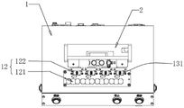
FIG. 1 is an overall schematic diagram of an intelligent bracelet heart rate function module test equipment according to an embodiment of the application.
FIG. 2 is the whole schematic diagram of a half-section of intelligent bracelet heart rate functional module test equipment test bench of the embodiment of the application.
FIG. 3 is an inside structure diagram of intelligent bracelet rhythm of heart functional module test equipment of this application embodiment.
FIG. 4 is a top view of the test carrier plate and the test connector installed in the test equipment for the heart rate function module of the smart band according to the embodiment of the present application.
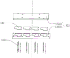
FIG. 5 is an explosion schematic diagram of a motherboard module along a motherboard module center in intelligent bracelet heart rate functional module test equipment according to an embodiment of the application.
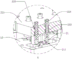
Fig. 6 is a schematic partial section view of a test carrier plate abutted by a light shield in an intelligent bracelet heart rate function module test device according to an embodiment of the application.
Fig. 7 is a partially enlarged view of a portion a in fig. 5.
Description of reference numerals: 1. a test bench; 11. a cavity; 12. testing the carrier plate; 121. positioning a groove; 122. a notch; 13. a testing device; 131. testing the joint; 132. a motherboard module; 1321. a circuit main board; 1322. a mounting seat; 13221. a cover plate; 13222. a base plate; 1323. a metal probe; 14. an induction device; 141. a trigger switch; 142. a connecting rod; 2. a mounting frame; 21. a light shield; 211. a housing chamber; 22. a moving assembly; 221. pressing a plate; 222. an elastic member; 223. a thin waist bolt; 224. a support pillar; 225. an annular projection; 23. a guide member; 231. a guide post; 232. a linear bearing; 24. a drive member.
Detailed Description
The present application is described in further detail below with reference to figures 1-6.
The embodiment of the application discloses intelligence bracelet rhythm of heart functional module test equipment. Referring to fig. 1, intelligence bracelet rhythm of heart functional module test equipment includes testboard 1 and mounting bracket 2, and mounting bracket 2 is fixed on testboard 1. Referring to fig. 2 and 3, the test stand 1 has a rectangular parallelepiped shape as a whole and is hollow inside, and a cavity 11 is formed inside. The test bench 1 comprises a test carrier plate 12, a test device 13 and a sensing device 14; the test carrier plate 12 is used for placing the smart bracelet heart rate function module, and the sensing device 14 is used for triggering the control test device 13 in the test process.
Referring to fig. 2 and 4, the test carrier 12 is a cuboid and is fixed on the upper surface of the test platform 1, a plurality of positioning grooves 121 for positioning the smart bracelet heart rate function module are formed in the test carrier 12, and in this embodiment, four positioning grooves 121 are uniformly formed in the test carrier 12. Testing arrangement 13 includes test connector 131 and mainboard module 132, and mainboard module 132 sets up in cavity 11, and test connector 131 is used for linking to each other with intelligent bracelet rhythm of the heart functional module, and mainboard module 132 is the required hardware core when testing, and intelligent bracelet rhythm of the heart functional module needs the electric connection to mainboard module 132 to test. Test connector 131 and mainboard module 132 electric connection, in the testing process, mainboard module 132 is as the article of accompanying and testing of intelligent bracelet rhythm of the heart functional module, chooses for use that mainboard module 132 that the test result is good can reduce the uncertain factor in the testing process. In the embodiment, the test socket 131 is in a rectangular parallelepiped shape, one side of the test carrier 12 is opened with four notches 122, the notches 122 are in a square shape, the four notches 122 are respectively communicated with the four positioning grooves 121 and can accommodate the test socket 131, and the test sockets 131 are respectively disposed in the four notches 122 and fixed on the upper surface of the test board 1.
Referring to fig. 5, the motherboard module 132 includes a circuit board 1321, a mounting seat 1322, and a metal probe 1323. Circuit mainboard 1321 is the core circuit board of intelligent bracelet, also is the carrier of intelligent bracelet rhythm of the heart functional module simultaneously, and mount pad 1322 is used for installing fixed circuit mainboard 1321, and metal probe 1323 is used for realizing the switching of circuit mainboard 1321 signal of telecommunication fast. The mounting seat 1322 includes a cover plate 13221 and a bottom plate 13222, the circuit board 1321 is placed between the cover plate 13221 and the bottom plate 13222, the cover plate 13221 and the bottom plate 13222 are fixedly connected, the metal probe 1323 is inserted on the bottom plate 13222, and an end of the metal probe 1323 abuts against a metal contact of the circuit board 1321. In the present embodiment, the cover 13221 and the bottom 13222 are each in a rectangular parallelepiped shape, the cover 13221 and the bottom 13222 are connected by bolts (not shown), and four circuit boards 1321 are disposed between the cover 13221 and the bottom 13222. When circuit board 1321 needs to be changed in the long-time test of experience, through the whole dismantlement of bolt fastening make things convenient for mount pad 1322 to circuit board 1321 realizes the signal of telecommunication switching through the mode of metal probe 1323 butt, conveniently changes circuit board 1321.
Referring to fig. 2 and 6, the mounting frame 2 includes a light shield 21, a moving assembly 22, a guide 23, and a driving member 24. Lens hood 21 is used for covering intelligent bracelet rhythm of heart functional module, reduces external light source in the test process, and removal subassembly 22 is used for driving lens hood 21 and slides and cover intelligent bracelet rhythm of heart functional module, and guide 23 is used for providing a glide path for removal subassembly 22, and driving piece 24 is used for the drive to remove subassembly 22 lift and slides. The light shield 21 is fixed on the moving assembly 22, the moving assembly 22 is connected with the mounting frame 2 in a sliding mode through the guide piece 23, and the driving piece 24 is fixed on the mounting frame 2.
Referring to fig. 6 and 7, the light shield 21 is made of a material having elasticity, and a black rubber material, which has high elasticity and has reversible deformation, is generally used. The light shield 21 is a cuboid, and has an accommodating chamber 211 along the bottom surface, and a simulated skin (not shown) is fixed in the accommodating chamber 211, and the simulated skin has a fixed frequency. When the light shield 21 covers the intelligent bracelet heart rate function module and starts a test, the intelligent bracelet heart rate function module emits test light, and the test light is absorbed by the simulated skin part and then reflected back to the intelligent bracelet heart rate function module; because the frequency of simulation skin change is fixed, whether the rhythm of the heart variation value received through analysis intelligence bracelet rhythm of the heart functional module is in the certain limit of simulation skin change default, judges whether intelligence bracelet rhythm of the heart functional module is good.
The moving assembly 22 includes a pressing plate 221, an elastic member 222, a thin waist bolt 223, and a supporting column 224. The pressing plate 221 is a cuboid, the light-shielding cover 21 is arranged on the bottom surface of the pressing plate 221, one side of the pressing plate 221, which is close to the test carrier plate 12, is provided with a plurality of light-shielding covers 21, the projection of the light-shielding covers 21 on the test carrier plate 12 is larger than the area of the notches of the positioning grooves 121, and the opening end surfaces of the light-shielding covers 21 are flush with the upper surface of the test carrier plate 12, when the light-shielding covers 21 slide and abut against the test carrier plate 12, the light-shielding covers 21 can completely cover the intelligent bracelet heart rate function module in the positioning grooves 121. Two slender bolts 223 are arranged on the pressing plate 221 at the corresponding positions of each light shield 21, the light shields 21 are fixed at one ends of the slender bolts 223 far away from the nuts, and elastic pieces 222 are arranged between the light shields 21 and the pressing plate 221; when the mask 21 slides against the test carrier 12, the mask 21 receives the supporting force from the test carrier 12, so that the elastic member 222 is compressed, the mask 21 and the pressing plate 221 slide relatively, the pressing plate 221 performs a deceleration motion relative to the mask 21, and the impact force of the mask 21 on the test carrier 12 is gradually reduced. The side surface of the pressing plate 221 close to the test carrier plate 12 is further provided with a supporting column 224, and the supporting column 224 is used for preventing the situation that the light shield 21 cannot completely cover the smart bracelet heart rate function module due to excessive compression and deformation of the light shield 21. The quantity of support column 224 is two, and two apex angles that two support columns 224 are close to clamp plate 221 respectively set up, through threaded connection between support column 224 and the clamp plate 221, through the support column 224 of chooseing for use different length, can be applicable to the test of the intelligent bracelet rhythm of the heart functional module of unidimensional. In the embodiment, four light-shielding masks 21 are disposed on the pressing plate 221, the positions of the four light-shielding masks 21 correspond to the positions of the positioning slots 121 on the test carrier 12 one by one, and the elastic members 222 are springs. Two through holes are formed in the position, corresponding to each light shield 21, of the pressing plate 221, the diameter of each through hole is larger than that of the corresponding nut, an annular bump 225 is arranged on the inner wall of each through hole, a thin waist bolt 223 penetrates through each through hole, and the surface of each screw rod is in sliding contact with the inner wall of the annular bump 225; the light shield 21 is fixed at one end of the screw rod far away from the screw cap in a threaded manner, and the spring is sleeved on the screw rod. When the spring is in an initial state, two ends of the spring respectively abut against the opposite inner sides between the light shield 21 and the annular convex block 225, and the other side of the annular convex block 225 abuts against the nut; when the spring is compressed, the light shielding mask 21 is pressed and deformed, and the light shielding mask 21 is abutted against the test carrier 12 more tightly.
The number of the guide 23 is two, and the guide 23 includes a guide post 231 and a linear bearing 232. One end of each guide post 231 is fixed on the test platform 1, the other end of each guide post 231 is fixed on the mounting frame 2, the two guide posts 231 are parallel to each other, and the axis of each guide post 231 is perpendicular to the upper surface of the test carrier plate 12. The linear bearings 232 are sleeved on the guide posts 231, the two linear bearings 232 are all arranged on the pressing plate 221 in a penetrating manner, and the axes of the two linear bearings 232 are perpendicular to the upper and lower surfaces of the pressing plate 221, so that the lower surface of the pressing plate 221 is parallel to the upper surface of the test carrier plate 12. In other embodiments, the guiding element 23 may also be a slide rail and a slider, the slide rail is disposed on the mounting frame 2, the length direction of the slide rail is perpendicular to the upper surface of the test carrier 12, and the slider is fixed on the pressing plate 221, so that the sliding effect of the pressing plate 221 is improved and the pressing plate 221 can be kept horizontal relative to the test carrier 12 through the sliding fit relationship between the slider and the slide rail.
Referring to fig. 3, in the present embodiment, the driving member 24 is an air cylinder, a cylinder body of the air cylinder is fixed on the mounting frame 2, and a piston rod of the air cylinder is fixed on the pressing plate 221. When the plunger rod extends, the pressing plate 221 slides towards the test carrier plate 12 until the light shield 21 abuts against the test carrier plate 12, the light shield 21 is partially deformed due to the pressing, and the spring between the pressing plate 221 and the light shield 21 is compressed until the supporting posts 224 abut against the pressing plate 221 and the test carrier plate 12 respectively; when the plunger rod is retracted, the spring between the pressing plate 221 and the light shield 21 releases the elastic force slowly, and the light shield 21 returns to the initial state slowly until the light shield 21 is far away from the test carrier board 12.
The sensing device 14 triggers a control signal after the light shield 21 covers the positioning slot 121, and the control signal is input into the motherboard module 132 to control the motherboard module 132 to start the test program. In this embodiment, the sensing device 14 includes a trigger switch 141 and a connecting rod 142, the trigger switch 141 is a mechanical press switch, the connecting rod 142 is fixed on the end surface of the pressing plate 221 close to the test carrier 12 and is disposed near a vertex angle of one point of the pressing plate 221, the length direction of the connecting rod 142 is the same as the sliding direction of the pressing plate 221, and the trigger switch 141 is disposed on the sliding path of the connecting rod 142. The trigger switch 141 is fixed on the top wall of the cavity 11 of the test board 1, and the trigger switch 141 is protected to prevent the trigger switch 141 from being touched by mistake and leading to the early start of the test. On testboard 1 and be located connecting rod 142 and set up porosely in the route department of sliding, when lens hood 21 covers intelligent bracelet rhythm of the heart module, connecting rod 142 passes the hole and butt and trigger switch 141. In other embodiments, the sensing device 14 may be a photoelectric sensor, the photoelectric sensor is fixed on the mounting frame 2 and is disposed on the sliding path of the pressing plate 221, and by adjusting the position of the photoelectric sensor, when the light shield 21 covers the smart band heart rate module, the pressing plate 221 blocks the transmission of the optical signal of the photoelectric sensor, so as to generate a trigger signal.
The implementation principle of the embodiment of the application is as follows: after the smart bracelet heart rate function module is placed in the positioning groove 121, the air cylinder drives the pressing plate 221 to slide towards the test carrier plate 12, the light shield 21 covers the smart bracelet heart rate function module in the positioning groove 121, the spring is gradually compressed until the supporting column 224 supports the pressing plate 221 and the test carrier plate 12, at the moment, the connecting rod 142 abuts against the trigger switch 141 and outputs a control signal, and the control signal triggers the main board module 132 to start a test program; test light is sent to intelligence bracelet rhythm of heart functional module, calculates the measured value between the simulation skin absorption reflection, and test completion back cylinder drive clamp plate 221 is kept away from test support plate 12 and is removed, and light shield 21 gets back to initial position under the effect of gravity and spring elastic force.
The above embodiments are preferred embodiments of the present application, and the protection scope of the present application is not limited by the above embodiments, so: all equivalent changes made according to the structure, shape and principle of the present application shall be covered by the protection scope of the present application.
Claims (8)
1. The utility model provides an intelligence bracelet rhythm of heart functional module test equipment which characterized in that: comprises a test board (1) and a mounting rack (2) fixed on the test board (1); the test bench (1) is provided with a test device (13) and a test carrier plate (12) for placing the intelligent bracelet heart rate function module, and the test device (13) comprises a test connector (131) connected with the intelligent bracelet heart rate function module; be provided with lens hood (21) of lift on mounting bracket (2), the opening terminal surface of lens hood (21) with test support plate (12) surface parallel and level and the projection on test support plate (12) cover intelligent bracelet rhythm of the heart function module.
2. The intelligent bracelet heart rate functional module testing device of claim 1, characterized in that: be provided with on mounting bracket (2) and remove subassembly (22), remove subassembly (22) with mounting bracket (2) slide and be connected, it includes clamp plate (221) and elastic component (222) to remove subassembly (22), lens hood (21) set up clamp plate (221) are close to one side of test support plate (12), the both ends of elastic component (222) are fixed respectively clamp plate (221) with lens hood (21) are last.
3. The intelligent bracelet heart rate functional module testing device of claim 2, characterized in that: a thin waist bolt (223) penetrates through the pressing plate (221), and the thin waist bolt (223) can slide relative to the pressing plate (221); the light shield (21) is fixed to one end, far away from the bolt cap, of the slender bolt (223) through threads, the elastic piece (222) is a spring, and the slender bolt (223) is sleeved with the spring.
4. The intelligent bracelet heart rate functional module testing device of claim 1, characterized in that: the light shield (21) is made of an elastic material.
5. The intelligent bracelet heart rate functional module testing device of claim 2, characterized in that: still be provided with driving piece (24) on mounting bracket (2), driving piece (24) order about removal subassembly (22) go up and down.
6. The intelligent bracelet heart rate functional module testing device of claim 2, characterized in that: and a supporting column (224) is detachably arranged on one side of the pressing plate (221) close to the test carrier plate (12).
7. The intelligent bracelet heart rate functional module testing device of claim 1, characterized in that: the testing device (13) further comprises a main board module (132), the main board module (132) comprises a circuit main board (1321), a mounting seat (1322) and a metal probe (1323), the mounting seat (1322) comprises a cover plate (13221) and a bottom plate (13222), the cover plate (13221) is connected with the bottom plate (13222) through bolts, the circuit main board (1321) is arranged between the cover plate (13221) and the bottom plate (13222), and the metal probe (1323) penetrates through the bottom plate (13222) and the end portion of the metal probe abuts against the circuit main board (1321).
8. The intelligent bracelet heart rate functional module testing device of claim 2, characterized in that: the test bench (1) is provided with a sensing device (14), and the sensing device (14) triggers a signal when the light shield (21) abuts against the test carrier plate (12); the induction device (14) comprises a trigger switch (141) and a connecting rod (142), the connecting rod (142) is detachably arranged on one side, close to the test carrier plate (12), of the pressing plate (221), and the trigger switch (141) is arranged on a sliding path of the connecting rod (142).
Priority Applications (1)
| Application Number | Priority Date | Filing Date | Title |
|---|---|---|---|
| CN202121839202.7U CN215728505U (en) | 2021-08-07 | 2021-08-07 | Intelligence bracelet rhythm of heart functional module test equipment |
Applications Claiming Priority (1)
| Application Number | Priority Date | Filing Date | Title |
|---|---|---|---|
| CN202121839202.7U CN215728505U (en) | 2021-08-07 | 2021-08-07 | Intelligence bracelet rhythm of heart functional module test equipment |
Publications (1)
| Publication Number | Publication Date |
|---|---|
| CN215728505U true CN215728505U (en) | 2022-02-01 |
Family
ID=79993641
Family Applications (1)
| Application Number | Title | Priority Date | Filing Date |
|---|---|---|---|
| CN202121839202.7U Active CN215728505U (en) | 2021-08-07 | 2021-08-07 | Intelligence bracelet rhythm of heart functional module test equipment |
Country Status (1)
| Country | Link |
|---|---|
| CN (1) | CN215728505U (en) |
Cited By (2)
| Publication number | Priority date | Publication date | Assignee | Title |
|---|---|---|---|---|
| CN115631549A (en) * | 2022-11-04 | 2023-01-20 | 深圳市卓讯达科技发展有限公司 | Testing method and testing equipment for wearable equipment |
| CN117169623A (en) * | 2023-08-18 | 2023-12-05 | 浙江普可医疗科技有限公司 | Testing device for detecting wearable flexible electrocardiograph monitoring |
-
2021
- 2021-08-07 CN CN202121839202.7U patent/CN215728505U/en active Active
Cited By (3)
| Publication number | Priority date | Publication date | Assignee | Title |
|---|---|---|---|---|
| CN115631549A (en) * | 2022-11-04 | 2023-01-20 | 深圳市卓讯达科技发展有限公司 | Testing method and testing equipment for wearable equipment |
| CN115631549B (en) * | 2022-11-04 | 2024-06-11 | 深圳市卓讯达科技发展有限公司 | A wearable device testing method and testing device |
| CN117169623A (en) * | 2023-08-18 | 2023-12-05 | 浙江普可医疗科技有限公司 | Testing device for detecting wearable flexible electrocardiograph monitoring |
Similar Documents
| Publication | Publication Date | Title |
|---|---|---|
| CN201672910U (en) | Off-line solder paste thickness gauge | |
| CN204101689U (en) | The checkout equipment of a kind of FPC | |
| CN113267717B (en) | Circuit board test platform | |
| CN217112576U (en) | Partial discharge detection device for high-voltage switch cabinet | |
| CN213780277U (en) | A PCB board function test fixture | |
| CN113301491B (en) | Positioning detection device and test platform for microphone | |
| CN114910776A (en) | Intensive testing arrangement of PCB board components and parts | |
| CN219015602U (en) | Electronic equipment testing device | |
| CN218445754U (en) | Electronic product testing device | |
| CN212514904U (en) | Automatic testing system for capacitive touch switch | |
| CN215116636U (en) | PCBA board test equipment convenient to fix | |
| CN215768806U (en) | Intelligence bracelet test equipment | |
| CN221936680U (en) | A testing device for computer hardware | |
| CN117053976B (en) | Three-dimensional force decoupling measurement device and method based on four-leaf grass type optical fiber junction array | |
| CN218512169U (en) | Stores pylon solder joint intensity testing arrangement | |
| CN115979550B (en) | Electronic equipment testing methods and electronic equipment testing devices | |
| CN217084503U (en) | Mechanical test equipment | |
| CN215726491U (en) | Micro-gap switch and mini switch contact elasticity test equipment | |
| CN217543720U (en) | Vehicle-mounted main control board product testing equipment | |
| CN214473644U (en) | Game paddle function test tool | |
| CN117169623A (en) | Testing device for detecting wearable flexible electrocardiograph monitoring | |
| CN113740656A (en) | Testing device | |
| CN208283278U (en) | Portable fluorescence agent detection device | |
| CN217954653U (en) | Bluetooth testing arrangement | |
| CN223513303U (en) | Circuit board tester for lateral touch spring type touch keys |
Legal Events
| Date | Code | Title | Description |
|---|---|---|---|
| GR01 | Patent grant | ||
| GR01 | Patent grant |