SUMMERY OF THE UTILITY MODEL
In view of the above disadvantages, the utility model provides a fixing device for an oxygen flow meter, which can adjust the telescopic distance and the size of clamping, meet the requirements of fixing and clamping various flow meters with different sizes, and has a simple structure, namely, the fixing device can be used after being bonded.
In order to achieve the purpose, the utility model adopts the following technical scheme:
the utility model provides an oxygen flow meter fixing device, includes sucking disc bottom, support, telescopic link and pipe strap clamp, the support is fixed to be set up on the sucking disc bottom, telescopic link one end is rotated and is set up on the support, other end fixed connection pipe strap clamp.
In a further preferable aspect of the present invention, the support includes a first support rod, a second support rod, a third support rod, and a telescopic rod placement block, one end of each of the first support rod, the second support rod, and the third support rod is respectively and fixedly disposed on the suction cup bottom at intervals, the other end of each of the first support rod, the second support rod, and the third support rod is joined to the telescopic rod placement block, so as to jointly support a triangular stable structure, and the telescopic rod placement block is connected to the telescopic rod.
In a further preferable scheme of the present invention, the telescopic rod includes a connecting rod, a sliding rod and an adjusting knob, the connecting rod is rotatably disposed on the telescopic rod placing block, the connecting rod is provided with a sliding groove, the sliding rod is slidably disposed on the connecting rod, the adjusting knob is disposed on the sliding rod, and the adjusting knob penetrates through the sliding groove to fix the sliding rod and the connecting rod.
In a further preferable aspect of the present invention, the connecting rod is a through rod, and a strip-shaped sliding groove is formed on the circumferential surface; the slide bar is a solid bar, a threaded hole is formed in the position, close to one end face, of the slide bar, and the adjusting knob is a screw rod.
In a further preferred embodiment of the present invention, the connecting rod and the sliding rod are made of metal.
In a further preferable scheme of the utility model, the pipe clamp comprises a left clamping block, a right clamping block, a hinge and a spring tying rope, the left clamping block and the right clamping block are rotatably connected through the hinge, the side surfaces of the free end edges of the left clamping block and the right clamping block are provided with hooks, and the spring tying rope is hung on the hooks on the clamping blocks.
In a further preferred aspect of the present invention, the left clamping block and the right clamping block are half arc-shaped plastic clamping blocks.
In a further preferred aspect of the present invention, an anti-slip rubber gasket is provided on the inner side of the pipe clamp.
In a further preferred embodiment of the present invention, the bottom of the sucker is made of a transparent and adsorptive soft rubber material.
Compared with the prior art, the utility model has the beneficial effects that:
the utility model provides a fixing device for an oxygen flow meter, which has simple structure and cheap and practical material selection, the triangular fixed state supported by three supporting rods ensures that the oxygen flow meter cannot overturn left and right due to infirm in the process, the fixing device has the function of length adjustment by telescopic matching of the connecting rod and the sliding rod, the distance size of the oxygen flow meter can be adjusted according to different sizes, the left clamping block and the right clamping block are semi-arc-shaped and are rotationally connected through a hinge, the left clamping block and the right clamping block are only required to be wrapped on the periphery of the oxygen flow meter when in clamping, and the clamping blocks are fastened through springs, the fixing device has the advantages that the clamping can be adjusted according to the size of the oxygen flow meter pipe, the non-fixed structure can meet the fixing effect on the meter pipes with various sizes, simultaneously, a fixed sucker at the bottom can be used by sticking, and no trace can be torn off after the fixing device is not needed, the vacuum chuck is a vacuum chuck and can be firmly stuck on a wall.
Detailed Description
The technical solution in the embodiments of the present invention will be clearly and completely described below with reference to the accompanying drawings in the embodiments of the present invention. It is to be understood that the described embodiments are merely exemplary of the utility model, and not restrictive of the full scope of the utility model. All other embodiments, which can be derived by a person skilled in the art from the embodiments given herein without making any creative effort, shall fall within the protection scope of the present invention.
In the description of the present invention, it should be noted that the terms "inside" and the like refer to an orientation or a positional relationship based on the orientation or the positional relationship shown in the drawings or an orientation or a positional relationship which is usually placed when the utility model is used, and are only used for convenience of describing the present invention and simplifying the description, but do not refer to or imply that the device or the element referred to must have a specific orientation, be constructed in a specific orientation and operate, and thus, cannot be construed as limiting the present invention.
In the description of the present invention, it should also be noted that, unless otherwise explicitly specified or limited, the terms "disposed" and "connected" are to be interpreted broadly, e.g., as being either fixedly connected, detachably connected, or integrally connected; can be mechanically or electrically connected; they may be connected directly or indirectly through intervening media, or they may be interconnected between two elements. The specific meanings of the above terms in the present invention can be understood in specific cases to those skilled in the art.
Example 1
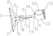
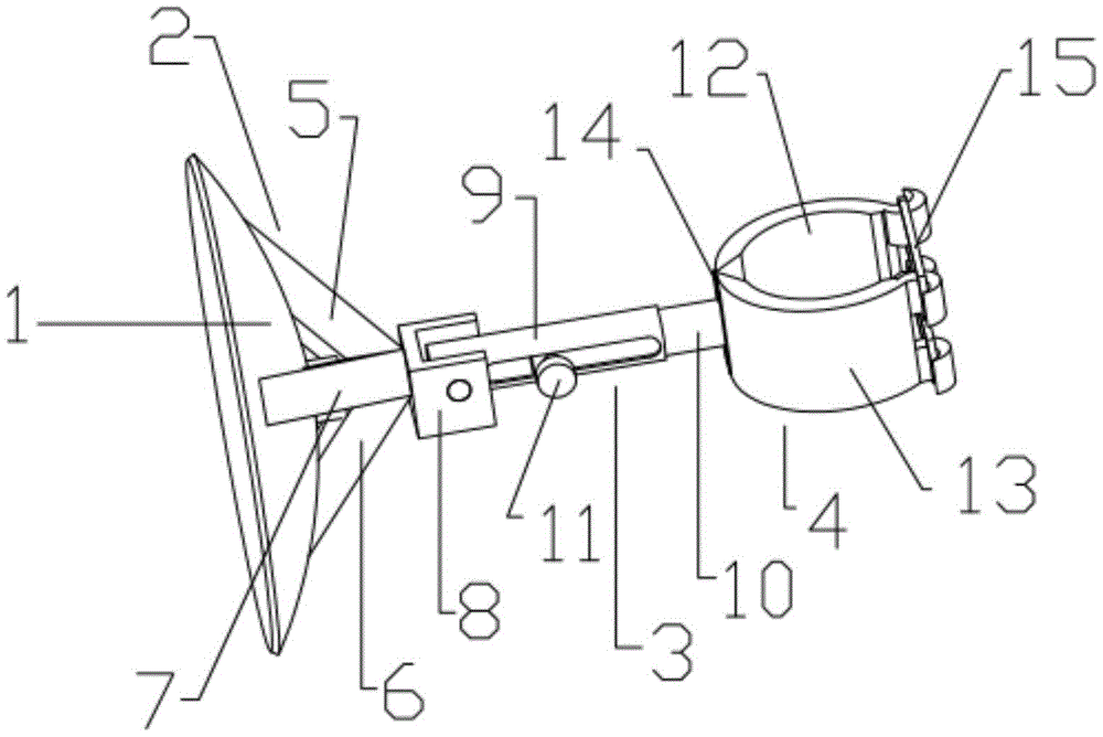
Referring to fig. 1, a preferred embodiment of the present invention provides a fixing device for an oxygen flowmeter, including a sucker bottom 1, a support 2, a telescopic rod 3 and a pipe clamp 4, where the support 2 is fixedly mounted on the sucker bottom 1, the support 2 includes a first support rod 5, a second support rod 6 and a third support rod 7, the three support rods jointly form a tripod stable structure, a tip angle formed by the three support rods faces away from the sucker bottom 1, a telescopic rod placing block 8 is fixedly arranged on the triangular end, the telescopic rod placing block 8 is rotatably provided with the telescopic rod 3, one end of the telescopic rod 3 is rotatably arranged on the triangular end of the support 2, and the other end of the telescopic rod 3 is fixedly connected with the pipe clamp 4, where the telescopic rod 3 further includes a connecting rod 9, a sliding rod 10 and an adjusting knob 11, the connecting rod 9 can rotate within 90 degrees on the telescopic rod 3 placing block 8, and the fixing device can be used by only needing to bend the telescopic rod 3 down to be perpendicular to the attaching surface of the sucker bottom 1 in use On the contrary, when the medical suction cup is not used, the telescopic rod 3 is broken to be parallel to the suction cup bottom 1, the medical suction cup has the advantages that a patient is prevented from accidentally colliding with the fixing device to be injured by the body, the safety and the attractiveness are guaranteed, the connecting rod 9 and the sliding rod 10 are in a sleeved relation, the connecting rod 9 is a through rod, the sliding rod 10 is a solid rod, the sliding rod 10 is sleeved in the rod cavity of the connecting rod 9 and can slide back and forth in the rod cavity of the connecting rod 9, a threaded hole is formed in the position, close to one end face, of the sliding rod 10, a strip-shaped sliding groove is formed in the peripheral face of the connecting rod, an adjusting knob 11 is arranged on the threaded hole, the adjusting knob 11 penetrates through the sliding groove and the threaded hole, the sliding rod 10 can only slide back and forth in the range of the sliding groove, the sliding rod 10 is placed to slide out of the connecting rod 9 when the sliding rod 10 is adjusted to a proper position, keep current stable position not to take place the slip skew through adjust knob 11 locking, the metal material is all chooseed for use to connecting rod 9 and slide bar 10 for fixing device is more durable, is difficult for taking place the condition of pole rupture at fixed in-process, the sucking disc end 1 is transparent and has the soft rubber material of adsorption capacity, utilizes the laminating of vacuum state firmly on the wall, tears not damaging the wall when not using moreover, can use repeatedly, has satisfied green's function.
The pipe clamp 4 is arranged on the telescopic free end face of the sliding rod 10, the pipe clamp 4 comprises a left clamping block 12, a right clamping block 13, a hinge 14 and a spring tether 15, an anti-slip rubber gasket is arranged on the inner side of the pipe clamp 4 and used for reinforcing and tightly holding a pipe body, the left clamping block 12 and the right clamping block 13 are rotatably connected through the hinge 14, the free opening and closing state can be realized, the clamping size of pipe diameters fixed by different oxygen flow meters can be adjusted at will, the left clamping block 12 and the right clamping block 13 are half arc-shaped plastic clamping blocks, the left clamping block 12 and the right clamping block 13 jointly form a round-like structure through the connection of the hinge 14, the round-like structure can be more fit with the shape of the pipe body to be clamped, the stability and the practicability in the clamping process are ensured, the structure is also designed on the production process, and is also economical and clean on selected materials, the clamp blocks made of plastic materials are very light and simple in weight, social requirements are met, one ends of the left clamp block 12 and the right clamp block 13 are connected through hinges 14, hooks are arranged on the side faces of the free end of the other end, a spring tying rope 15 is hung and buckled on the hooks on the clamp blocks, when clamping of the oxygen flowmeter pipe diameter is completed, the spring tying rope 15 is hung and tightly connected on the hooks on the left clamp block and the right clamp block, so that the pipe clamp can further clamp the pipe diameter to be clamped to prevent loosening and the left clamp block and the right clamp block from overturning, the spring tying rope 15 is a common spring rubber rope on the market, if other ropes are not easily available for replacement, the fixing device is simple and universal, and the clamping state of the left clamp block and the right clamp block to the clamped pipe diameter is guaranteed through elastic tightening after the spring tying rope 15.
Compare in oxygen flow meter fixing device on present market, the device simple structure, and the price is substantial, manufacturing cost is also suitable, it is higher for other instrument class fixing device platforms practicality of bulky and complicated structure, the device is similar to the couple mode, glue promptly and use, do not tear the time spent and do not harm the wall, utilize vacuum chuck's effect can firmly adsorb on the wall, this sucking disc still can use repeatedly, convenient and fast, and the device small in size is multi-functional again, be equipped with the telescopic link, scalable regulation length distance, the pipe strap clamp is set up to two half splint structures, through hinge connection, but the tight regulation centre gripping chi footpath, to the oxygen flow meter of different chi footpaths and do different chi footpaths centre gripping change, make this flow meter fixing device be applicable to do the centre gripping fixed to the instrument of various pipe diameters.
The working principle of the fixing device of the oxygen flow meter in the embodiment is as follows:
the utility model provides a fixing device for an oxygen flow meter, which is simple in structure and is provided with a sucker bottom 1, a bracket 2, a telescopic rod 3 and a pipe clamp 4, wherein the bracket 2 is in a stable structure in a triangular state, so that the device is prevented from shaking left and right when the oxygen flow meter is fixed, the length of the telescopic rod 3 can be adjusted to adjust the position distance of a clamping pipe diameter, the pipe clamp 4 is formed by connecting a left clamping block 12 and a right clamping block 13 through a hinge 14, and has the functions of opening and closing to adjust the clamping ruler diameter, the size of the clamping ruler diameter can be adjusted according to the pipe diameter size, the use of oxygen flow meters with various sizes and specifications is met, and simultaneously, this telescopic link 3 sets up on the piece 8 is placed to the telescopic link, can 90 degrees from top to bottom freely overturn, and upset when not using is accomodate to adsorbing plane parallel state with the sucking disc bottom 1 to prevent that the patient from hitting the device carelessly and causing human injury.
The oxygen flow meter fixing device in this example is used as follows:
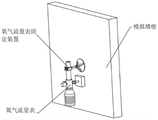
1. before using the oxygen flow meter fixing device, firstly, the oxygen flow meter is installed and connected on a wall nutrient supplying machine, and the position to be adhered of the fixing device is determined by righting the aerobic flow meter;
2. pressing the bottom of a sucker of the oxygen flow meter fixing device to a position to be adhered, determining that air is completely exhausted, and firmly adsorbing the sucker on the wall surface;
3. loosening an adjusting knob on the oxygen flow meter, sliding a sliding rod to the position where the telescopic length of the telescopic rod is shortest, breaking the telescopic rod down by 90 degrees to enable the telescopic rod to be vertical to the bottom of a sucking disc, then righting the oxygen flow meter by one hand, pulling a pipe clamp to the pipe diameter of the oxygen flow meter by the other hand, clamping the pipe diameter by a left clamping block and a right clamping block of the pipe clamp, tying the pipe clamp on barbs on the left clamping block and the right clamping block by using a spring tying rope, and ensuring that the pipe diameter of the oxygen flow meter is clamped tightly by the pipe clamp;
4. finally, screwing the adjusting knob to ensure that the positions of the sliding rod and the connecting rod do not deviate and slide, and finishing installation and fixation;
5. after the sucker is used, the adjusting knob is loosened, the spring tying rope is taken down, the left clamping block and the right clamping block are opened, the sliding rod slides into the connecting rod, then the telescopic rod is broken up until the telescopic rod and the sucking disc bottom adsorption plane are in a parallel state, and 2-4 steps are repeated until the sucker is used next time.
The above description is only for the specific embodiment of the present invention, but the scope of the present invention is not limited thereto, and any changes or substitutions that can be easily conceived by those skilled in the art within the technical scope of the present invention are included in the scope of the present invention. Therefore, the protection scope of the present invention shall be subject to the protection scope of the appended claims.