CN215715808U - A kind of sewage water seal deodorization structure - Google Patents
A kind of sewage water seal deodorization structure Download PDFInfo
- Publication number
- CN215715808U CN215715808U CN202122088427.XU CN202122088427U CN215715808U CN 215715808 U CN215715808 U CN 215715808U CN 202122088427 U CN202122088427 U CN 202122088427U CN 215715808 U CN215715808 U CN 215715808U
- Authority
- CN
- China
- Prior art keywords
- water
- sewer
- sewer body
- ring
- sealing
- Prior art date
- Legal status (The legal status is an assumption and is not a legal conclusion. Google has not performed a legal analysis and makes no representation as to the accuracy of the status listed.)
- Active
Links
- XLYOFNOQVPJJNP-UHFFFAOYSA-N water Substances O XLYOFNOQVPJJNP-UHFFFAOYSA-N 0.000 title claims abstract description 136
- 238000004332 deodorization Methods 0.000 title claims abstract description 8
- 239000010865 sewage Substances 0.000 title description 2
- 239000002781 deodorant agent Substances 0.000 claims abstract 5
- 238000007789 sealing Methods 0.000 claims description 46
- 239000007788 liquid Substances 0.000 abstract description 5
- 238000009434 installation Methods 0.000 abstract description 4
- 238000005452 bending Methods 0.000 abstract description 3
- 238000004519 manufacturing process Methods 0.000 abstract description 2
- 238000000926 separation method Methods 0.000 abstract description 2
- 238000005516 engineering process Methods 0.000 abstract 1
- 238000003825 pressing Methods 0.000 description 3
- 238000003860 storage Methods 0.000 description 1
Images




Landscapes
- Sink And Installation For Waste Water (AREA)
Abstract
The utility model discloses a sewer water seal deodorization structure which comprises a sewer body, wherein a water inlet is formed in the side wall of the sewer body, a flow guide ring is arranged in the inner cavity of the sewer body, the flow guide ring extends along the length direction of the sewer body, and a bent flow guide groove is formed between the flow guide ring and the inner wall of the sewer body. This deodorant structure of offal water seal, inside through at the offal body sets up the water conservancy diversion ring, at the inside crooked guiding gutter that forms of offal body, water inlet and delivery port communicate with guiding gutter one end respectively, when stopping the drainage, water is full of the most space of guiding gutter, separation water inlet and delivery port, realize the liquid seal, prevent anti-smelly, change the bending type of current water seal, realize the water seal through inside guiding gutter, the volume of water seal has been reduced, the space that occupies when having reduced the installation, be convenient for use at the installation of narrow space more, also make the outward appearance more pleasing to the eye, the while production technology is also simpler.
Description
Technical Field
The utility model relates to the technical field of sewers, in particular to a sewer water seal deodorization structure.
Background
The water seal is a water column with a certain height in the device to prevent gas in the drainage pipe system from flowing into the room. In a drainage pipe of a building, a water seal is arranged below a drainage port of a sanitary ware to resist the change of air pressure difference in the drainage pipe and prevent gas in a drainage pipe system from entering a water column at a certain height in a room, and is generally realized by a trap. The water seal is a separation mode for separating two parts of gas to be separated by using water.
The existing water seal is generally in a bent shape and is S-shaped, the water storage space is realized in the inner part by the bending of the appearance, so that water sealing is realized, the water seal completely depends on the appearance to realize water sealing, the whole volume is large, the occupied space is large during installation, inconvenience is caused by the use in a narrow space, and the production process is complex.
Therefore, how to change the structure of the water seal and reduce the volume of the water seal is an urgent technical problem to be solved in the industry, so that the water seal is convenient to install in a narrow space.
SUMMERY OF THE UTILITY MODEL
The utility model mainly aims to provide a sewer water seal deodorization structure, aiming at changing the structure of a water seal and reducing the volume of the water seal structure, thereby being convenient to install in a narrow space.
The utility model provides a sewer water seal deodorization structure which comprises a sewer body, wherein a water inlet is formed in the side wall of the sewer body, a flow guide ring is arranged in the inner cavity of the sewer body, the flow guide ring extends along the length direction of the sewer body, a bent flow guide groove is formed between the flow guide ring and the inner wall of the sewer body, the water inlet is communicated with one end of the flow guide groove, a water drainage port is formed in the surface of the sewer body, the water drainage port is communicated with the other end of the flow guide groove, and the outer end of the water drainage port is communicated with a water drainage pipe.
Preferably, the front end of the launching body is open, the opening of the launching body is provided with a sealing assembly, the sealing assembly comprises a water sealing pad, a water sealing pressing plate and a water sealing nut, the water sealing pad covers the opening of the front end of the launching body, the water sealing nut is in threaded connection with the front end of the launching body, and the water sealing pressing plate is arranged inside the water sealing nut and tightly presses the front end of the water sealing pad.
Preferably, the drain pipe and the drain opening are detachably connected through threads.
Preferably, the guide ring is in an open ring shape, one end of the guide ring is fixedly connected with the upper part of the inner wall surface of the lower water body, the formed guide groove is in a vortex shape, the water inlet is communicated with the outer end of the guide groove, the other end of the guide groove is positioned at the center of the section of the inner cavity of the lower water body, and the water outlet is arranged at the center of the rear end surface of the lower water body and is communicated with the inner end of the guide groove.
Preferably, the guide ring is arc-shaped, two ends of the guide ring are respectively fixedly connected with the upper part of the inner wall surface of the lower water body, the formed guide groove is in an open ring shape, the water inlet is communicated with one end of the guide groove, and the water outlet is arranged on the upper part of the side surface of the lower water body and is communicated with the other end of the guide groove.
Preferably, the drainage body and the guide ring are integrally formed.
According to the utility model, the diversion ring is arranged in the drainage body, the curved diversion trench is formed in the drainage body, the water inlet and the water outlet are respectively communicated with one end of the diversion trench, when drainage is stopped, most space of the diversion trench is filled with water, the water inlet and the water outlet are blocked, liquid seal is realized, and odor is prevented.
Drawings
FIG. 1 is an exploded view of the present invention;
FIG. 2 is a schematic view of the external structure of the present invention;
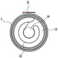
FIG. 3 is a schematic view of an embodiment of a cross section of a downcomer body of the present invention;
FIG. 4 is a schematic cross-sectional view of the present invention;
FIG. 5 is an exploded view of an embodiment of the present invention;
FIG. 6 is an external view of an embodiment of the present invention;
FIG. 7 is a schematic view of a cross-section of a lower body according to an embodiment of the present invention;
FIG. 8 is a cross-sectional view of an embodiment of the present invention.
In the figure: 1. the water draining device comprises a water draining body, 11, a water inlet, 12, a flow guide ring, 13, a flow guide groove, 14, a water draining opening, 2, a water sealing pad, 3, a water sealing pressure plate, 4, a water sealing screw cap, 5 and a water draining pipe.
The implementation, functional features and advantages of the objects of the present invention will be further explained with reference to the accompanying drawings.
Detailed Description
It should be understood that the specific embodiments described herein are merely illustrative of the utility model and are not intended to limit the utility model.
Referring to fig. 1-4, an embodiment of the present invention is provided, which includes a drainage body 1, a water inlet 11 is disposed on a side wall of the drainage body 1, a flow guide ring 12 is disposed in an inner cavity of the drainage body 1, the flow guide ring 12 extends along a length direction of the drainage body 1, a curved flow guide groove 13 is formed between the flow guide ring 12 and an inner wall of the drainage body 1, the water inlet 11 is communicated with one end of the flow guide groove 13, a drainage port 14 is disposed on a surface of the drainage body 1, the drainage port 14 is communicated with another end of the flow guide groove 13, and an outer end of the drainage port 14 is communicated with a drainage pipe 5.
The sewage flows in from the water inlet 11, flows to the direction of the water outlet 14 through the guide of the guide groove 13, when the water quantity is large, the water flow continuously flows to the water outlet 14 and flows into the drain pipe 5 through the water outlet 14, the drainage is realized, the residual water continuously flows in the guide groove 13, the guide groove 13 is sealed, the water sealing is realized, and the odor is prevented from being reversed.
Further, the front end of the lower water body 1 is open, the opening of the lower water body 1 is provided with a sealing assembly, the sealing assembly comprises a water sealing pad 2, a water sealing pressure plate 3 and a water sealing nut 4, the water sealing pad 2 covers the opening of the front end of the lower water body 1, the water sealing nut 4 is in threaded connection with the front end of the lower water body 1, and the water sealing pressure plate 3 is arranged in the water sealing nut 4 and tightly presses the front end of the water sealing pad 2.
The outer ring of the front side surface of the water sealing pressure plate 3 is provided with a concave ring which is embedded with the inner ring of the water sealing screw cap 4, so that the water sealing pressure plate 3 is pressed on the water sealing pad 2, the water sealing pad 2 is pressed at the opening at the front end of the launching body 1, and sealing is realized.
After using one end time, unscrew water sealing nut 4 to open water sealing clamp plate 3 and water sealing pad 2, clear up attachments such as the inside sedimentary rubbish of launching body 1, prevent to influence the drainage.
Further, the drain pipe 6 is detachably connected to the drain port 14 by a screw.
The outer end of the water outlet 14 extends to the outside of the water drainage body 1, and is provided with an external thread on the surface, and the front end of the water drainage pipe 6 is provided with an internal thread which are matched with each other to realize detachable connection.
Further, the sewer body 1 and the deflector ring 12 are integrally formed.
Further, the guide ring 12 is in an open ring shape, one end of the guide ring is fixedly connected with the upper part of the inner wall surface of the lower water body 1, the formed guide groove 13 is in a vortex shape, the water inlet 11 is communicated with the outer end of the guide groove 13, the other end of the guide groove 13 is positioned at the center of the cross section of the inner cavity of the lower water body 1, and the water outlet 14 is arranged at the center of the rear end surface of the lower water body 1 and is communicated with the inner end of the guide groove 13.
During drainage, water flows through the highest point of the inner end of the guide ring 12 and flows downwards into the position of the drainage outlet 14, after drainage is stopped, the liquid level and the highest point of the inner end of the guide ring 12 are in the same horizontal plane, most of space below the guide groove 13 is filled, the guide groove 13 is sealed, water sealing is realized, and odor is prevented from being removed.
As shown in fig. 4-8, another embodiment of the present invention is provided, in this embodiment, the diversion ring 12 is arc-shaped, two ends of the diversion ring are respectively and fixedly connected with the upper portion of the inner wall surface of the lower water body 1, the formed diversion trench 13 is in an open ring shape, the water inlet 11 is communicated with one end of the diversion trench 13, and the water outlet 14 is arranged at the upper portion of the side surface of the lower water body 1 and is communicated with the other end of the diversion trench 13.
During drainage, water flows to the joint of the diversion trench 13 and the drainage outlet 14 and then enters the drainage outlet 14 to be drained, after drainage is stopped, the liquid level is kept at the height of the diversion trench 13, which is flush with the lowest point of the drainage outlet 14, and all the space of the diversion trench 13 below the drainage outlet 14 is filled, water sealing is realized, and odor is prevented from being removed.
Through all setting up the liquid seal part inside launching body 1, change the bending modeling of current water seal, realize the water seal through inside guiding gutter 13, reduced the volume of water seal, the space that occupies when having reduced the installation, be more convenient for install and use in narrow space, also make the outward appearance more pleasing to the eye.
In use, the water inlet 11 should be located directly above.
When the water seal device works, the water seal pad 2 is placed at the port position of the lower water body 1, the water seal pressing plate 3 is placed on the lower water body 1, the water seal screw cap 4 is fixed on the lower water body 1, and finally the corresponding connecting parts are connected at the positions of the water inlet 11 and the water outlet 14.
The above description is only for the preferred embodiment of the present invention and is not intended to limit the scope of the present invention, and all equivalent structural changes made by using the contents of the present specification and the drawings, or any other related technical fields, are included in the scope of the present invention.
Claims (6)
Priority Applications (1)
| Application Number | Priority Date | Filing Date | Title |
|---|---|---|---|
| CN202122088427.XU CN215715808U (en) | 2021-09-01 | 2021-09-01 | A kind of sewage water seal deodorization structure |
Applications Claiming Priority (1)
| Application Number | Priority Date | Filing Date | Title |
|---|---|---|---|
| CN202122088427.XU CN215715808U (en) | 2021-09-01 | 2021-09-01 | A kind of sewage water seal deodorization structure |
Publications (1)
| Publication Number | Publication Date |
|---|---|
| CN215715808U true CN215715808U (en) | 2022-02-01 |
Family
ID=80010556
Family Applications (1)
| Application Number | Title | Priority Date | Filing Date |
|---|---|---|---|
| CN202122088427.XU Active CN215715808U (en) | 2021-09-01 | 2021-09-01 | A kind of sewage water seal deodorization structure |
Country Status (1)
| Country | Link |
|---|---|
| CN (1) | CN215715808U (en) |
Cited By (1)
| Publication number | Priority date | Publication date | Assignee | Title |
|---|---|---|---|---|
| CN115094990A (en) * | 2022-07-21 | 2022-09-23 | 沈阳九日实业有限公司 | Sealing device with positive and negative pressure resistant water seal protection function |
-
2021
- 2021-09-01 CN CN202122088427.XU patent/CN215715808U/en active Active
Cited By (1)
| Publication number | Priority date | Publication date | Assignee | Title |
|---|---|---|---|---|
| CN115094990A (en) * | 2022-07-21 | 2022-09-23 | 沈阳九日实业有限公司 | Sealing device with positive and negative pressure resistant water seal protection function |
Similar Documents
| Publication | Publication Date | Title |
|---|---|---|
| CN100414047C (en) | self-sealing floor drain | |
| CN106759810B (en) | High-flow horizontal water-sealed floor drain | |
| CN105040800A (en) | Double-guarantee floor drain | |
| CN215630450U (en) | A water-sealed deodorant structure | |
| CN103147494A (en) | Water trough drainer and water trough drainer deodorization method | |
| CN217500487U (en) | Novel deodorant floor drain of floater formula | |
| CN212294889U (en) | Anti-leakage submerged floor drain pipeline structure | |
| CN203174708U (en) | Water tank drainer | |
| CN201437610U (en) | A kind of micro-loss in-line floor drain | |
| CN209243881U (en) | A kind of odor-proof floor drain | |
| CN202466775U (en) | Deodorization-type urinal water-drain assembly and urinal provided with same | |
| CN203498923U (en) | Deodorizing drainer and bathtub using same | |
| CN201485924U (en) | Sanitary appliance sewage deodorizing device | |
| CN105155660A (en) | Deodorant drainer | |
| CN217078977U (en) | Rear-mounted drainer | |
| CN210369165U (en) | Novel flexible deodorant drainage system | |
| CN213897356U (en) | Ultra-short deodorant drainer | |
| CN212742795U (en) | Drainage pipeline prevents flowing backward device | |
| CN209891344U (en) | Pre-buried floor drain of balcony | |
| CN211596943U (en) | Sewer pipe for washbasin | |
| CN218091185U (en) | Floor drain for clean room | |
| CN210827721U (en) | Stinking-proof sewer pipe joint | |
| CN204311553U (en) | A kind of floor drain of huge discharge odor-resistant anti-clogging overflow-proof band filtering function | |
| CN217078981U (en) | Anti-blocking drainage pipeline | |
| CN208430596U (en) | Multifunctional deodorization is precious |
Legal Events
| Date | Code | Title | Description |
|---|---|---|---|
| GR01 | Patent grant | ||
| GR01 | Patent grant |