CN215703232U - Waste rubber crusher - Google Patents
Waste rubber crusher Download PDFInfo
- Publication number
- CN215703232U CN215703232U CN202121867903.1U CN202121867903U CN215703232U CN 215703232 U CN215703232 U CN 215703232U CN 202121867903 U CN202121867903 U CN 202121867903U CN 215703232 U CN215703232 U CN 215703232U
- Authority
- CN
- China
- Prior art keywords
- crushing
- negative pressure
- waste rubber
- counterattack
- dust removal
- Prior art date
- Legal status (The legal status is an assumption and is not a legal conclusion. Google has not performed a legal analysis and makes no representation as to the accuracy of the status listed.)
- Expired - Fee Related
Links
Images


Classifications
-
- Y—GENERAL TAGGING OF NEW TECHNOLOGICAL DEVELOPMENTS; GENERAL TAGGING OF CROSS-SECTIONAL TECHNOLOGIES SPANNING OVER SEVERAL SECTIONS OF THE IPC; TECHNICAL SUBJECTS COVERED BY FORMER USPC CROSS-REFERENCE ART COLLECTIONS [XRACs] AND DIGESTS
- Y02—TECHNOLOGIES OR APPLICATIONS FOR MITIGATION OR ADAPTATION AGAINST CLIMATE CHANGE
- Y02W—CLIMATE CHANGE MITIGATION TECHNOLOGIES RELATED TO WASTEWATER TREATMENT OR WASTE MANAGEMENT
- Y02W30/00—Technologies for solid waste management
- Y02W30/50—Reuse, recycling or recovery technologies
- Y02W30/52—Mechanical processing of waste for the recovery of materials, e.g. crushing, shredding, separation or disassembly
-
- Y—GENERAL TAGGING OF NEW TECHNOLOGICAL DEVELOPMENTS; GENERAL TAGGING OF CROSS-SECTIONAL TECHNOLOGIES SPANNING OVER SEVERAL SECTIONS OF THE IPC; TECHNICAL SUBJECTS COVERED BY FORMER USPC CROSS-REFERENCE ART COLLECTIONS [XRACs] AND DIGESTS
- Y02—TECHNOLOGIES OR APPLICATIONS FOR MITIGATION OR ADAPTATION AGAINST CLIMATE CHANGE
- Y02W—CLIMATE CHANGE MITIGATION TECHNOLOGIES RELATED TO WASTEWATER TREATMENT OR WASTE MANAGEMENT
- Y02W30/00—Technologies for solid waste management
- Y02W30/50—Reuse, recycling or recovery technologies
- Y02W30/62—Plastics recycling; Rubber recycling
Landscapes
- Crushing And Pulverization Processes (AREA)
Abstract
The utility model discloses a waste rubber crusher which comprises a case, wherein a feeding hole is formed in one side of the case, the feeding hole is connected with a feeding hopper, a screw conveyor is arranged below the feeding hole, a crushing cavity is formed in the case, a crushing cutter set is arranged in the crushing cavity, a material door capable of being automatically opened and closed is arranged at the top of the feeding hopper, a material guiding slope is arranged at the bottom of the crushing cavity, a plurality of air suction ports are formed in the material guiding slope, and the air suction ports are connected with a dust removal device on one side through negative pressure pipes. The rubber particle crusher has the advantages of novel structure, reasonable design, good crushing effect, prevention of dust raising, reduction of adverse effects on the surrounding environment, direct realization of separation of crushed rubber particles and dust, and great improvement of working efficiency.
Description
Technical Field
The utility model relates to the technical field of rubber processing, in particular to a waste rubber crusher.
Background
The rubber crusher is a necessary device for recycling and granulating waste rubber products. The rubber crusher cuts, extrudes and crushes the large tires and the waste plastics to obtain the fine and small rubber particles. However, when the rubber crusher is used for crushing, dust is often large, and some particles even splash out from the feeding hole.
Prior art CN 204955203U discloses a waste rubber crusher, which comprises a case, wherein a feed inlet is formed in one side of the top of the case, a feeding device is installed below the feed inlet, a reaction plate is arranged behind the crushing device, a filter plate is arranged below the crushing device, a collecting hopper is arranged below the filter plate, and a rotor component is arranged below the collecting hopper. However, the technology still has some defects: a large amount of dust generally exists in waste rubber, and the waste rubber is easy to become dust to fly in the crushing process. Not only influences the surrounding environment, but also can be mixed in the broken rubber particles and can not be separated.
SUMMERY OF THE UTILITY MODEL
In order to solve the defects, the utility model aims to provide the waste rubber crusher which has a good crushing effect and avoids dust emission, and can separate crushed rubber particles from dust.
In order to achieve the purpose, the utility model is realized by the following technical scheme: the utility model provides an old and useless rubber crusher, includes quick-witted case, and quick-witted case one side is equipped with the feed inlet, and the feed inlet is connected with the feeder hopper, and the feed inlet below is equipped with screw conveyer, and quick-witted incasement is equipped with broken chamber, and broken intracavity is equipped with broken knife tackle, and the feeder hopper top is equipped with the bin gate that can open and close automatically, and broken chamber bottom is equipped with the guide slope, is equipped with a plurality of inlet scoops on the guide slope, and the inlet scoop passes through the negative pressure pipe and is connected with the dust collector of one side. The bin gate can realize automatic switching at the during operation, prevents that the dust from raising out from the feed inlet. The suction inlet on the material guide slope at the bottom of the crushing cavity realizes negative pressure in the crushing cavity through the negative pressure pipe, and dust in sucked air is concentrated in the dust removal device, so that the purpose of dust removal is realized.
Further, be equipped with corresponding infrared emission end and infrared receiving terminal on the lateral wall of the feeder hopper of bin gate top, be fixed with electric putter on the lateral wall of feeder hopper of bin gate below, the bin gate downside is equipped with the spout, is equipped with the slider in the spout, installs the mount pad on the slider, and electric putter's tip is articulated with the mount pad, and infrared emission end, infrared receiving terminal, electric putter pass through the controller electricity and connect. Infrared emission end and infrared receiving terminal have formed a detection area in the bin gate top, and when old and useless rubber products got into this detection area, the light that the infrared emission end sent was sheltered from, and the infrared receiving terminal just signals when can not receiving light, and electric putter work drives the slider in the spout and slides, makes the bin gate open. When no new old and useless rubber products enter, the infrared ray receiving terminal can receive the light that the infrared ray emission end sent, and the infrared ray receiving terminal signals, and electric putter work drives the slider slip in the spout, makes the bin gate close.
Furthermore, the crushing cutter set comprises two crushing rotating shafts penetrating through the crushing cavity, blades and auxiliary steel thorns are arranged on the crushing rotating shafts, and a counterattack plate set is arranged on one side of the crushing cutter set. The crushing rotating shaft, the blade, the auxiliary steel prick and the impact plate group act together, so that waste rubber products can be crushed more uniformly and more thoroughly during implementation. The impact plate group can prevent rubber particles from flying randomly during crushing, reduce the impact force of the inner wall of the crushing cavity and prolong the service life.
Furthermore, the impact plate group comprises a fixed impact plate and a movable impact plate, the fixed impact plate comprises a fixed impact part and a positioning part, the positioning part is fixed on the side wall of the crushing cavity on the upper side of the crushing cutter group through a fastener, the movable impact plate comprises a movable impact part and a telescopic mechanism, the movable impact part is connected with the side wall of the crushing cavity on the lower side of the crushing cutter group through the telescopic mechanism, and one side of the fixed impact part and one side of the movable impact part are both provided with impact teeth. The fixed impact plate and the movable impact plate can effectively buffer the impact force applied to the crushing cavity, reduce the abrasion of the inner wall of the crushing cavity and further finely crush the waste rubber products.
Furthermore, the end part of the crushing rotating shaft is provided with a wind wheel. The wind wheel can produce centrifugal force, and waste rubber ceaselessly moves in the crushing cavity while being crushed, so that repeated crushing is realized, and the crushing effect is increased.
Further, dust collector includes the dust removal box, the negative pressure case of dust removal box internal and negative pressure pipe UNICOM, and the negative pressure incasement is equipped with the filter bag, and negative pressure bottom of the case portion is equipped with the dust removal case of intercommunication. The negative pressure pipe enables the inside of the crushing cavity to form negative pressure, and dust in the sucked air is intercepted by the filter bag in the dust removal box body and falls into the dust removal box body, so that the purpose of dust removal is achieved.
The utility model has the beneficial effects that:
1. the feed hopper department sets up the bin gate that can automatic switching, surveys through the infrared emission end and the infrared receiving end of bin gate top whether have old and useless rubber products to get into the feed hopper to signal gives electric putter, and electric putter drives the slider slip in the spout, makes the bin gate open or close. Thereby playing the role of preventing the dust from flying out from the feed hopper.
2. The inlet scoop of guide slope department of broken chamber bottom passes through the negative pressure pipe and pumps the dust in broken chamber to dust collector and connect in, with the dust separation of adulteration in the rubber granule tone after the breakage, when lifting and avoiding the raise dust, improves the quality of rubber granule.
3. The crushing rotating shaft, the blade, the auxiliary steel prick and the impact plate group in the crushing cavity act together, so that waste rubber products can be crushed more uniformly during working, and the crushing is more thorough. The impact plate group can prevent rubber particles from flying randomly during crushing, reduce the impact force of the inner wall of the crushing cavity and prolong the service life.
The rubber particle crusher has the advantages of novel structure, reasonable design, good crushing effect, prevention of dust raising, reduction of adverse effects on the surrounding environment, direct realization of separation of crushed rubber particles and dust, and great improvement of working efficiency.
Drawings
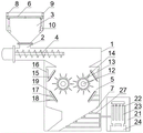
FIG. 1 is a schematic structural diagram of the present invention.
Fig. 2 is a schematic view of the structure of the feed hopper of the present invention.
Fig. 3 is a schematic structural view of the crushing cutter set of the present invention.
Wherein: 1. the device comprises a case, 2, a feeding hole, 3, a feeding hopper, 4, a screw conveyor, 5, a crushing cavity, 6, a material door, 7, a material guide slope, 8, an infrared transmitting end, 9, an infrared receiving end, 10, an electric push rod, 11, a mounting seat, 12, a crushing rotating shaft, 13, a blade, 14, an auxiliary steel prick, 15, a fixed counterattack part, 16, a positioning part, 17, a movable counterattack part, 18, a telescopic mechanism, 19, counterattack teeth, 20, a wind wheel, 21, a dust removal case body, 22, a negative pressure case, 23, a filter bag, 24, a dust removal case, 25, a sliding groove, 26, a sliding block, 27 and a negative pressure pipe.
Detailed Description
The technical solutions in the embodiments of the present invention will be clearly and completely described below with reference to the drawings in the embodiments of the present invention, and it is obvious that the described embodiments are only a part of the embodiments of the present invention, and not all of the embodiments. All other embodiments, which can be derived by a person skilled in the art from the embodiments given herein without making any creative effort, shall fall within the protection scope of the present invention.
Referring to fig. 1, the present invention provides a technical solution: the utility model provides an old and useless rubber crusher, includes quick- witted case 1, and 1 one side of quick-witted case is equipped with feed inlet 2, and feed inlet 2 is connected with feeder hopper 3, and 2 below of feed inlet are equipped with screw conveyer 4, are equipped with broken chamber 5 in the quick-witted case 1, are equipped with broken knife tackle in broken chamber 5, and 3 tops of feeder hopper are equipped with the bin gate 6 that can automatic switching, and 5 bottoms in broken chamber are equipped with guide slope 7, are equipped with a plurality of inlet scoops on the guide slope 7, and the inlet scoop passes through negative pressure tube 27 and is connected with the dust collector of one side. The material door 6 can be automatically opened and closed during working, and dust is prevented from being blown out of the feeding hole 2. The screw conveyor 4 transports the used rubber products from the hopper 3 to the crushing chamber 5. The crushing cutter group in the crushing cavity 5 crushes the waste rubber products. The air suction opening on the material guiding slope 7 at the bottom of the crushing cavity 5 realizes negative pressure in the crushing cavity 5 through the negative pressure pipe 27, and dust in sucked air is concentrated in the dust removal device, so that the purpose of dust removal is realized.
As shown in fig. 2, the material gate 6 is automatically opened. Be equipped with corresponding infrared emission end 8 and infrared receiving terminal 9 on the lateral wall of the feeder hopper 3 of bin gate 6 top, be fixed with electric putter 10 on the lateral wall of feeder hopper 3 of bin gate 6 below, the 6 downside of bin gate is equipped with spout 25, be equipped with slider 26 in the spout 25, install mount pad 11 on the slider 26, electric putter 10's tip and mount pad 11 are articulated, infrared emission end 8, infrared receiving terminal 9, electric putter 10 pass through the controller electricity and connect. Install infrared emission end 8 and infrared receiving terminal 9 on two about the lateral wall of feeder hopper 3 of bin gate 6 top respectively, just formed a detection zone in bin gate 6 top, when old and useless rubber products got into this detection zone, the light that infrared emission end 8 sent was sheltered from, and infrared receiving terminal 9 just signals when can not receive light, and electric putter 10 work drives the slider 26 in the spout 25 and slides, makes bin gate 6 open. When no new waste rubber product enters, as shown in fig. 1, the infrared receiving end 9 can receive the light emitted from the infrared emitting end 8, the infrared receiving end 9 sends a signal, and the electric push rod 10 operates to drive the sliding block 26 in the sliding groove 25 to slide, so that the material door 6 is closed.
As shown in fig. 3, the crushing cutter set comprises two crushing rotating shafts 12 penetrating through the crushing cavity 5, the crushing rotating shafts 12 are provided with blades 13 and auxiliary steel thorns 14, and one side of the crushing cutter set is provided with a reaction plate set. The crushing rotating shaft 12, the blade 13, the auxiliary steel prick 14 and the impact plate group act together, so that waste rubber products can be crushed more uniformly and more thoroughly during implementation. The impact plate group can prevent rubber particles from flying randomly during crushing, reduce the impact force on the inner wall of the crushing cavity 5 and prolong the service life.
The impact plate set comprises a fixed impact plate and a movable impact plate, the fixed impact plate comprises a fixed impact part 15 and a positioning part 16, the positioning part 16 is fixed on the side wall of the crushing cavity 5 on the upper side of the crushing cutter set through a fastener, the movable impact plate comprises a movable impact part 17 and a telescopic mechanism 18, the movable impact part 17 is connected with the side wall of the crushing cavity 5 on the lower side of the crushing cutter set through the telescopic mechanism 18, and one side of the fixed impact part 15 and one side of the movable impact part 17 are both provided with impact teeth 19. Decide impact plate and move impact plate can effectual buffering crushing chamber 5 receive the impact force, reduce the wearing and tearing of 5 inner walls in crushing chamber, further meticulous breakage to waste rubber product simultaneously.
The end of the crushing rotating shaft 12 is provided with a wind wheel 20. The wind wheels 20 on the two crushing rotating shafts 12 are respectively arranged at different end parts, centrifugal force is produced under the combined action of the two wind wheels 20 and the crushing cutter set, waste rubber ceaselessly moves in the crushing cavity 5 while being crushed, repeated crushing is realized, and the crushing effect is increased.
The dust removing device comprises a dust removing box body 21, a negative pressure box 22 communicated with a negative pressure pipe 27 is arranged in the dust removing box body 21, a filter bag 23 is arranged in the negative pressure box 22, and a dust removing box 24 communicated with the bottom of the negative pressure box 22 is arranged. The negative pressure pipe 27 forms negative pressure in the crushing cavity 5 to suck the air in the crushing cavity 5, and the dust in the sucked air is intercepted by the filter bag 23 in the dust removing box body 21, and falls into the dust removing box 24 below the bottom of the negative pressure box 22 outside the filter bag 23, thereby realizing the purpose of dust removal.
When the utility model is implemented, waste rubber products are poured into the feeding hopper 3 at the feeding hole 2 on the case 1, light rays emitted by the infrared emitting end 8 are shielded, a signal is emitted when the infrared receiving end 9 cannot receive the light rays, the electric push rod 10 works to drive the slide block 26 in the slide groove 25 to slide, and the material door 6 is opened. After entering the machine case 1, the waste rubber products are conveyed into the crushing cavity 5 by the screw conveyor 4. The crushing rotating shaft 12, the blade 13, the auxiliary steel prick 14 and the impact plate group are used for crushing the waste rubber products together, and comprehensive treatment can ensure that the waste rubber products can be crushed more uniformly and more thoroughly during implementation. The fixed impact part 15 and the movable impact part 17 of the impact plate group work together, so that rubber particles do not fly randomly during crushing, the impact force on the inner wall of the crushing cavity 5 is reduced, and the service life is prolonged. The wind wheels 20 on the two crushing rotating shafts 12 are respectively arranged at different end parts, centrifugal force is produced under the combined action of the two wind wheels 20 and the crushing cutter set, waste rubber ceaselessly moves in the crushing cavity 5 while being crushed, repeated crushing is realized, and the crushing effect is increased. The crushed rubber particles finally fall onto the material guiding slope 7, the suction inlet on the material guiding slope 7 realizes negative pressure in the crushing cavity 5 through the negative pressure pipe 27, dust in the sucked air is intercepted by the filter bag 23 in the dust removal box body 21, and the dust in the filter bag 23 falls into the dust removal box 24 below the bottom of the negative pressure box 22, so that the purpose of dust removal is realized. When no old and useless rubber products pour into, the light that infrared emission end 8 sent can be received to infrared receiving end 9, and infrared receiving end 9 signals, and electric putter 10 work drives the slider 26 slip in the spout 25, makes bin gate 6 close, prevents that the dust, and rubber granule from splashing out from feed inlet 2.
Although embodiments of the present invention have been shown and described, it will be appreciated by those skilled in the art that changes, modifications, substitutions and alterations can be made in these embodiments without departing from the principles and spirit of the utility model, the scope of which is defined in the appended claims and their equivalents.
Claims (6)
Priority Applications (1)
| Application Number | Priority Date | Filing Date | Title |
|---|---|---|---|
| CN202121867903.1U CN215703232U (en) | 2021-08-11 | 2021-08-11 | Waste rubber crusher |
Applications Claiming Priority (1)
| Application Number | Priority Date | Filing Date | Title |
|---|---|---|---|
| CN202121867903.1U CN215703232U (en) | 2021-08-11 | 2021-08-11 | Waste rubber crusher |
Publications (1)
| Publication Number | Publication Date |
|---|---|
| CN215703232U true CN215703232U (en) | 2022-02-01 |
Family
ID=79994688
Family Applications (1)
| Application Number | Title | Priority Date | Filing Date |
|---|---|---|---|
| CN202121867903.1U Expired - Fee Related CN215703232U (en) | 2021-08-11 | 2021-08-11 | Waste rubber crusher |
Country Status (1)
| Country | Link |
|---|---|
| CN (1) | CN215703232U (en) |
Cited By (1)
| Publication number | Priority date | Publication date | Assignee | Title |
|---|---|---|---|---|
| CN116277569A (en) * | 2023-01-09 | 2023-06-23 | 江苏贝特尔电气有限公司 | A raw material premixing device for damping spacer rubber parts |
-
2021
- 2021-08-11 CN CN202121867903.1U patent/CN215703232U/en not_active Expired - Fee Related
Cited By (1)
| Publication number | Priority date | Publication date | Assignee | Title |
|---|---|---|---|---|
| CN116277569A (en) * | 2023-01-09 | 2023-06-23 | 江苏贝特尔电气有限公司 | A raw material premixing device for damping spacer rubber parts |
Similar Documents
| Publication | Publication Date | Title |
|---|---|---|
| CN221334478U (en) | Raw coal crusher | |
| CN106582980B (en) | It can carry out the feed stuff reducing device of separating twice | |
| CN211051596U (en) | Screening and crushing device for recycling positive electrode of waste battery | |
| CN210500979U (en) | Plastics are reducing mechanism in grades | |
| CN209985544U (en) | Novel ore crushing device | |
| CN111633873A (en) | An injection molding residual material crushing device | |
| CN210079716U (en) | Wooden active carbon particle crushing mechanism | |
| CN219820314U (en) | Rubber slab section reducing mechanism | |
| CN213032716U (en) | A carbon residue crushing device | |
| CN214800935U (en) | Reducing mechanism is used in straw fermentation | |
| CN213133358U (en) | Scratch-resistant powder coating sheet crushing device | |
| CN216261202U (en) | Aluminum ash environmental protection treatment facility | |
| CN211526453U (en) | Boiler waste residue pretreatment equipment | |
| CN111135920A (en) | Food grinder | |
| CN211246805U (en) | Uniform crushing device for high polymer materials | |
| CN211678154U (en) | High polymer material reducing mechanism | |
| CN222918779U (en) | Rubber products processing waste material collection device | |
| CN210022322U (en) | Feed back system of mineral powder vertical mill | |
| CN211755632U (en) | Dust-proof coal gangue crushing device | |
| CN219943090U (en) | Fodder crushed aggregates edulcoration machine | |
| CN222248875U (en) | A raw material crushing device for biomass fuel | |
| CN221982588U (en) | Environment-friendly pulverizer | |
| CN220879175U (en) | Crusher with screening function for coal mine | |
| CN219943020U (en) | Automatic deironing reducing mechanism is used to mineral processing equipment | |
| CN222567949U (en) | Reducing mechanism is used in feed additive production |
Legal Events
| Date | Code | Title | Description |
|---|---|---|---|
| GR01 | Patent grant | ||
| GR01 | Patent grant | ||
| CF01 | Termination of patent right due to non-payment of annual fee |
Granted publication date: 20220201 |
|
| CF01 | Termination of patent right due to non-payment of annual fee |