CN215692427U - A dust collector - Google Patents
A dust collector Download PDFInfo
- Publication number
- CN215692427U CN215692427U CN202121941641.9U CN202121941641U CN215692427U CN 215692427 U CN215692427 U CN 215692427U CN 202121941641 U CN202121941641 U CN 202121941641U CN 215692427 U CN215692427 U CN 215692427U
- Authority
- CN
- China
- Prior art keywords
- dust
- dust remover
- remover
- dust collector
- box
- Prior art date
- Legal status (The legal status is an assumption and is not a legal conclusion. Google has not performed a legal analysis and makes no representation as to the accuracy of the status listed.)
- Expired - Fee Related
Links
Images

Landscapes
- Filtering Of Dispersed Particles In Gases (AREA)
Abstract
The utility model belongs to the technical field of dust collectors, and relates to a dust collector dust removal device which comprises a dust collector, wherein a support plate is arranged in the dust collector, a plurality of dust removal cylinders are arranged on the support plate, a gas compression bottle is arranged on one side of the dust collector, a valve is arranged on one side of the gas compression bottle, a connecting pipe is fixedly connected to the gas compression bottle, a bifurcated pipe is arranged at one end of the connecting pipe, which is positioned in the dust collector, a pulse head is arranged on the bifurcated pipe, the pulse head is positioned in the dust removal cylinders, a hopper box is arranged on the bottom surface of the dust collector, a filter plate is arranged in the hopper box, a dust collection mechanism is arranged on the bottom surface of the hopper box, a rotating head is arranged at the output end of a driving motor, a plurality of fan blades are arranged on the rotating head, an air inlet pipe is arranged on the top surface of the dust collector, two exhaust pipes are arranged on one side of the dust collector, a first box door is rotatably connected to the front side of the dust collector, a second box door is rotatably connected to facilitate dust removal in equipment, the device is prevented from being blocked due to excessive dust in the device.
Description
Technical Field
The utility model belongs to the technical field of dust collectors, and particularly relates to a dust removing device of a dust collector.
Background
The filter cartridge dust remover consists of a filter cartridge as a filter element or adopts a pulse blowing dust remover. The filter cartridge dust remover can be divided into an inclined insertion type, a side-mounted type, a hoisting type and an upper-mounted type according to the mounting mode. The filter cartridge dust remover can be divided into a long fiber polyester filter cartridge dust remover, a composite fiber filter cartridge dust remover, an anti-static filter cartridge dust remover, a flame-retardant filter cartridge dust remover, a membrane-coated filter cartridge dust remover, a nanometer filter cartridge dust remover and the like according to filter cartridge materials, but in the dust removing process of the dust remover, more dust can be generated inside the dust remover, and if the dust inside the dust remover is not cleaned, the internal blockage can be caused, so that the dust removing effect of equipment is seriously influenced.
SUMMERY OF THE UTILITY MODEL
The utility model provides a dust remover ash removal device for solving the problems.
In order to solve the technical problems, the utility model provides the following technical scheme:
a dust remover ash cleaning device comprises a dust remover, wherein a supporting plate is installed in the dust remover, a plurality of dust removing cylinders are installed on the supporting plate, a gas compression bottle is installed on one side of the dust remover, a valve is installed on one side of the gas compression bottle, a connecting pipe is fixedly connected to the gas compression bottle, a bifurcated pipe is installed at one end, located in the dust remover, of the connecting pipe, a pulse head is installed on the bifurcated pipe and located in the dust removing cylinders, a screen plate is installed in the dust remover and located below the supporting plate, the other end of the dust removing cylinder is movably connected to the screen plate, a funnel box is installed on the bottom surface of the dust remover, a filter plate is installed in the funnel box, a dust suction mechanism is installed on the bottom surface of the funnel box and comprises a protective shell, a driving motor, a rotating head and fan blades, and a protective shell is installed on the bottom surface of the funnel box, the dust remover comprises a protective shell, and is characterized in that a driving motor is installed in the protective shell, a rotating head is installed at the output end of the driving motor, a plurality of fan blades are arranged on the rotating head, an air inlet pipe is arranged on the top surface of the dust remover, two exhaust pipes are arranged on one side of the dust remover, a first box door is rotationally connected to the front side of the dust remover, a second box door is rotationally connected to the front side of the dust remover, and the second box door is located below the first box door.
As a preferred technical scheme of the utility model, a cloth bag dedusting layer is arranged on the surface of the dedusting cylinder, and the dedusting cylinder is detachable; the dust removing cylinder is convenient to replace and disassemble.
As a preferred technical scheme of the utility model, the surface of the valve is provided with a rubber anti-skid layer, the bifurcated pipe is E-shaped and is positioned in the dust removing cylinder; the pulse head is convenient to clean dust in the dust removing cylinder.
As a preferred technical scheme of the utility model, one side of the protective shell is provided with a closed movable plate, and the closed movable plate is positioned outside the protective shell; when the equipment is used for cleaning dust, the dust suction mechanism at the bottom is in a closed state, so that the gas of the equipment is prevented from leaking from the bottom.
As a preferred technical scheme of the utility model, the first box door and the second box door are both provided with a rotating handle, the surfaces of the rotating handles are provided with rubber anti-skid layers, and the joints of the first box door, the second box door and the dust remover are both provided with sealing strips; the first box door and the second box door are convenient to open, the friction force of an operator can be increased, and people can open the box more conveniently.
As a preferred technical scheme of the utility model, four supporting seats are arranged on the bottom surface of the dust remover, the four supporting seats are positioned at four corners of the bottom surface of the dust remover, and rubber anti-collision layers are arranged on the supporting seats; the dust removal stability is convenient to improve.
The utility model has the following beneficial effects:
1. in the utility model, the compressed gas in the gas compression bottle enters the bifurcated pipe from the connecting pipe by opening the valve, the pulse head arranged on the bifurcated pipe impacts the gas in the bifurcated pipe to the dust removal cylinder, the dust removal cylinder is influenced by the gas to scatter the dust on the dust removal cylinder, and the dust on the inner side and the outer side of the dust removal cylinder falls off under the action of the gas, so that the dust cleaning efficiency is effectively improved, and the problem that the work efficiency of equipment is influenced by repeatedly detaching the dust removal cylinder is avoided.
2. Open the driving motor among the dust absorption mechanism, make driving motor work, when driving motor during operation, the rotating head of driving motor output installation rotates, the flabellum of installation rotates on the rotating head, when the flabellum rotates, the flabellum drives the air and flows, a dust removal section of thick bamboo falls into on the filter through the screen plate that leaks through the dust of pulse head clearance, the air drives the dust and enters into the filter, clean air is discharged by the protective housing opposite side, can open second chamber door clearance filter after the dust clearance is accomplished, the efficiency of effectual improvement dust clearance.
Drawings
The accompanying drawings, which are included to provide a further understanding of the utility model and are incorporated in and constitute a part of this specification, illustrate embodiments of the utility model and together with the description serve to explain the principles of the utility model and not to limit the utility model. In the drawings:
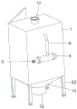
FIG. 1 is a first schematic structural diagram of the present invention;
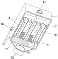
FIG. 2 is a second schematic structural view of the present invention;
FIG. 3 is a front cross-sectional structural schematic view of the present invention;
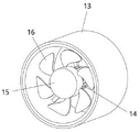
fig. 4 is a partial structural schematic diagram of the present invention.
In the figure: 1. a dust remover; 2. a support plate; 3. a dust removal cylinder; 4. a gas compression bottle; 5. a valve; 6. a connecting pipe; 7. a bifurcated tube; 8. a pulse head; 9. a screen plate; 10. a filter plate; 11. a hopper box; 12. a dust suction mechanism; 13. a protective shell; 14. a drive motor; 15. rotating the head; 16. a fan blade; 17. an air inlet pipe; 18. an exhaust pipe; 19. a first door; 20. rotating the handle; 21. a second door; 22. and (4) supporting the base.
Detailed Description
The technical solutions in the embodiments of the present invention will be clearly and completely described below with reference to the drawings in the embodiments of the present invention, and it is obvious that the described embodiments are only a part of the embodiments of the present invention, and not all of the embodiments. All other embodiments, which can be derived by a person skilled in the art from the embodiments given herein without making any creative effort, shall fall within the protection scope of the present invention.
Example (b): as shown in fig. 1-4, a dust cleaning device for a dust collector comprises a dust collector 1, a support plate 2 is installed in the dust collector 1, a plurality of dust collecting cylinders 3 are installed on the support plate 2, a gas compression bottle 4 is installed on one side of the dust collector 1, a valve 5 is installed on one side of the gas compression bottle 4, a connecting pipe 6 is fixedly connected to the gas compression bottle 4, a bifurcated pipe 7 is installed at one end of the connecting pipe 6 positioned in the dust collector 1, a pulse head 8 is installed on the bifurcated pipe 7, the pulse head 8 is positioned in the dust collecting cylinder 3, a screen plate 9 is installed in the dust collector 1, the screen plate 9 is positioned below the support plate 2, the other end of the dust collecting cylinder 3 is movably connected to the screen plate 9, a funnel box 11 is installed on the bottom surface of the dust collector 1, a filter plate 10 is installed in the funnel box 11, a dust collecting mechanism 12 is installed on the bottom surface of the funnel box 11, the dust collecting mechanism 12 comprises a protective shell 13, a driving motor 14, a rotating head 15 and fan blades 16, the protection shell 13 is installed on the bottom surface of the funnel box 11, the driving motor 14 is installed in the protection shell 13, the rotating head 15 is installed at the output end of the driving motor 14, the plurality of fan blades 16 are arranged on the rotating head 15, the air inlet pipe 17 is arranged on the top surface of the dust remover 1, the two exhaust pipes 18 are arranged on one side of the dust remover 1, the first box door 19 is connected to the front side of the dust remover 1 in a rotating mode, the second box door 21 is connected to the front side of the dust remover 1 in a rotating mode, and the second box door 21 is located below the first box door 19.
The surface of the dust removing cylinder 3 is provided with a cloth bag dust removing layer, and the dust removing cylinder 3 is detachable; the dust removing cylinder 3 is convenient to replace and disassemble; the surface of the valve 5 is provided with a rubber anti-skid layer, the bifurcated pipe 7 is E-shaped, and the bifurcated pipe 7 is positioned in the dust removing cylinder 3; the pulse head 8 is convenient to clean the dust in the dust removing cylinder 3; a closed movable plate is arranged on one side of the protective shell 13 and is positioned on the outer side of the protective shell 13; when the equipment is used for cleaning dust, the dust suction mechanism 12 at the bottom is in a closed state, so that the gas of the equipment is prevented from leaking from the bottom; the first box door 19 and the second box door 21 are both provided with a rotating handle 20, the surface of the rotating handle 20 is provided with a rubber anti-skid layer, and the joints of the first box door 19, the second box door 21 and the dust remover 1 are both provided with sealing strips; the first box door 19 and the second box door 21 can be opened conveniently, so that the friction force of an operator can be increased, and people can open the box more conveniently; four supporting seats 22 are arranged on the bottom surface of the dust remover 1, the four supporting seats 22 are positioned at four corners of the bottom surface of the dust remover 1, and rubber anti-collision layers are arranged on the supporting seats 22; the dust removal stability is convenient to improve.
Specifically, when the dust removal device is used, the air inlet pipe 17 is connected with other equipment, air enters the dust remover 1, the dust removal cylinder 3 in the dust remover 1 filters the air, the filtered air is discharged through the exhaust pipe 18, dust in the dust removal cylinder 3 or the equipment can be cleaned after the filtered air is discharged, the valve 5 is opened, compressed air in the air compression bottle 4 enters the branch pipe 7 through the connecting pipe 6, the pulse head 8 arranged on the branch pipe 7 impacts the air in the branch pipe 7 onto the dust removal cylinder 3, the dust removal cylinder 3 is influenced by the air to scatter the dust on the dust removal cylinder 3, the dust on the inner side and the outer side of the dust removal cylinder 3 falls off under the action of the air, the dust removal efficiency is effectively improved, the phenomenon that the dust removal cylinder 3 is repeatedly dismounted to influence the working efficiency of the equipment is avoided, the driving motor 14 in the dust removal mechanism 12 is opened to enable the driving motor 14 to work, when driving motor 14 during operation, the rotating head 15 of 14 output installations of driving motor rotates, the flabellum 16 of installation rotates on the rotating head 15, when flabellum 16 rotates, flabellum 16 drives the air and flows, dust removal section of thick bamboo 3 falls into on filter 10 through the hourglass otter board 9 through the dust of the first 8 clearance of pulse, the air drives the dust and enters into in the filter 10, clean air is discharged by protective housing 13 opposite side, can open second chamber door 21 clearance filter 10 after the dust clearance is accomplished, the efficiency of effectual improvement dust clearance.
In the description of the present invention, it is to be understood that the terms "coaxial", "bottom", "one end", "top", "middle", "other end", "upper", "one side", "top", "inner", "front", "center", "both ends", and the like, indicate orientations or positional relationships based on those shown in the drawings, and are only for convenience of description and simplicity of description, and do not indicate or imply that the referenced device or element must have a particular orientation, be constructed and operated in a particular orientation, and thus, are not to be construed as limiting the present invention.
Furthermore, the terms "first", "second", "third", "fourth" are used for descriptive purposes only and are not to be construed as indicating or implying a relative importance or implicitly indicating the number of technical features indicated, whereby the features defined as "first", "second", "third", "fourth" may explicitly or implicitly include at least one such feature.
In the present invention, unless otherwise expressly specified or limited, the terms "mounted," "disposed," "connected," "secured," "screwed" and the like are to be construed broadly, e.g., as meaning fixedly connected, detachably connected, or integrally formed; can be mechanically or electrically connected; the terms may be directly connected or indirectly connected through an intermediate, and may be communication between two elements or interaction relationship between two elements, unless otherwise specifically limited, and the specific meaning of the terms in the present invention will be understood by those skilled in the art according to specific situations.
Although embodiments of the present invention have been shown and described, it will be appreciated by those skilled in the art that changes, modifications, substitutions and alterations can be made in these embodiments without departing from the principles and spirit of the utility model, the scope of which is defined in the appended claims and their equivalents.
Claims (6)
1. The utility model provides a dust remover ash removal device, includes dust remover (1), its characterized in that: the dust remover is characterized in that a supporting plate (2) is installed in the dust remover (1), a plurality of dust removing cylinders (3) are installed on the supporting plate (2), a gas compression bottle (4) is installed on one side of the dust remover (1), a valve (5) is installed on one side of the gas compression bottle (4), a connecting pipe (6) is fixedly connected onto the gas compression bottle (4), a bifurcated pipe (7) is installed at one end of the connecting pipe (6) positioned in the dust remover (1), a pulse head (8) is installed on the bifurcated pipe (7), the pulse head (8) is positioned in the dust removing cylinders (3), a screen plate (9) is installed in the dust remover (1), the screen plate (9) is positioned below the supporting plate (2), the other ends of the dust removing cylinders (3) are movably connected onto the screen plate (9), a funnel box (11) is installed on the bottom surface of the dust remover (1), and a filter plate (10) is installed in the funnel box (11), dust absorption mechanism (12) are installed to funnel case (11) bottom surface, dust absorption mechanism (12) are including protective housing (13), driving motor (14), rotating head (15) and flabellum (16), funnel case (11) bottom surface installation protective housing (13), installation driving motor (14) in protective housing (13), driving motor (14) output installation rotating head (15), be equipped with a plurality of flabellums (16) on rotating head (15), dust remover (1) top surface is equipped with intake pipe (17), dust remover (1) one side is equipped with two blast pipes (18), dust remover (1) front side rotation is connected with first chamber door (19), dust remover (1) front side rotation is connected with second chamber door (21), second chamber door (21) are located first chamber door (19) below.
2. The ash removal device for dust collectors of claim 1, wherein: the surface of the dust removing cylinder (3) is provided with a cloth bag dust removing layer, and the dust removing cylinder (3) is detachable.
3. The ash removal device for dust collectors of claim 1, wherein: the valve (5) surface is equipped with the rubber skid resistant course, bifurcated pipe (7) are the E shape, bifurcated pipe (7) are located dust removal cylinder (3).
4. The ash removal device for dust collectors of claim 1, wherein: a closed movable plate is arranged on one side of the protective shell (13) and located on the outer side of the protective shell (13).
5. The ash removal device for dust collectors of claim 1, wherein: the dust remover is characterized in that a rotating handle (20) is arranged on each of the first box door (19) and the second box door (21), a rubber anti-slip layer is arranged on the surface of the rotating handle (20), and sealing strips are arranged at the joints of the first box door (19), the second box door (21) and the dust remover (1).
6. The ash removal device for dust collectors of claim 1, wherein: four supporting seats (22) are installed on the bottom surface of the dust remover (1), the supporting seats (22) are located at four corners of the bottom surface of the dust remover (1), and a rubber anti-collision layer is arranged on the supporting seats (22).
Priority Applications (1)
| Application Number | Priority Date | Filing Date | Title |
|---|---|---|---|
| CN202121941641.9U CN215692427U (en) | 2021-08-18 | 2021-08-18 | A dust collector |
Applications Claiming Priority (1)
| Application Number | Priority Date | Filing Date | Title |
|---|---|---|---|
| CN202121941641.9U CN215692427U (en) | 2021-08-18 | 2021-08-18 | A dust collector |
Publications (1)
| Publication Number | Publication Date |
|---|---|
| CN215692427U true CN215692427U (en) | 2022-02-01 |
Family
ID=79998099
Family Applications (1)
| Application Number | Title | Priority Date | Filing Date |
|---|---|---|---|
| CN202121941641.9U Expired - Fee Related CN215692427U (en) | 2021-08-18 | 2021-08-18 | A dust collector |
Country Status (1)
| Country | Link |
|---|---|
| CN (1) | CN215692427U (en) |
-
2021
- 2021-08-18 CN CN202121941641.9U patent/CN215692427U/en not_active Expired - Fee Related
Similar Documents
| Publication | Publication Date | Title |
|---|---|---|
| CN222445785U (en) | Gauze type pulse filter cartridge dust remover | |
| CN107158826B (en) | A kind of bag-type dust collector | |
| CN210993450U (en) | Filter cartridge dust remover for environmental protection | |
| CN2727429Y (en) | Cleaning and dust-collecting device for air filter element of internal combustion engine | |
| CN215311037U (en) | Filter cartridge dust remover convenient for filter cartridge replacement | |
| CN218687513U (en) | Industrial dust removal device capable of removing dust in grading manner | |
| CN218573143U (en) | Dust recovery device | |
| CN217549257U (en) | Engineering machine tool air filter dust remover | |
| CN213555926U (en) | Bag-type dust collector | |
| CN211462437U (en) | Pulse dust removal equipment convenient to clearance function | |
| CN214289902U (en) | Multistage dust arrester installation of gypsum production line | |
| CN210497508U (en) | Purging device for atmospheric dust detector | |
| CN222889571U (en) | Small dust collecting device | |
| CN211008871U (en) | High-efficient high dust holding capacity box type fine filter of gas turbine | |
| CN222711199U (en) | Automatic welding device | |
| CN210931164U (en) | Dust collecting box for dust collector | |
| CN223667863U (en) | Industrial dust collector capable of removing dust rapidly | |
| CN206965359U (en) | A high-efficiency pulse bag filter | |
| CN220194346U (en) | Dust filter for spraying | |
| CN217119703U (en) | Array dust shaker | |
| CN113856347A (en) | Novel energy-efficient dust exhausting fan | |
| CN212072295U (en) | Wood chip collecting device used in wood processing workshop | |
| CN220912756U (en) | Workshop dust is with collecting detection device | |
| CN221432413U (en) | Compact air purifying device | |
| CN223581496U (en) | Anti-blocking sampling head of gas detection sampling machine |
Legal Events
| Date | Code | Title | Description |
|---|---|---|---|
| GR01 | Patent grant | ||
| GR01 | Patent grant | ||
| CF01 | Termination of patent right due to non-payment of annual fee |
Granted publication date: 20220201 |
|
| CF01 | Termination of patent right due to non-payment of annual fee |