CN215674173U - Device is reinforceed to directly buried pipeline dog-ear - Google Patents
Device is reinforceed to directly buried pipeline dog-ear Download PDFInfo
- Publication number
- CN215674173U CN215674173U CN202122347507.2U CN202122347507U CN215674173U CN 215674173 U CN215674173 U CN 215674173U CN 202122347507 U CN202122347507 U CN 202122347507U CN 215674173 U CN215674173 U CN 215674173U
- Authority
- CN
- China
- Prior art keywords
- fixed
- cladding
- angle
- covering member
- pipeline
- Prior art date
- Legal status (The legal status is an assumption and is not a legal conclusion. Google has not performed a legal analysis and makes no representation as to the accuracy of the status listed.)
- Active
Links
- 239000011248 coating agent Substances 0.000 claims abstract description 34
- 238000000576 coating method Methods 0.000 claims abstract description 34
- 238000005253 cladding Methods 0.000 claims description 47
- 210000001503 joint Anatomy 0.000 claims description 15
- 230000003014 reinforcing effect Effects 0.000 claims description 3
- 230000007704 transition Effects 0.000 claims description 3
- 238000003466 welding Methods 0.000 claims description 3
- 230000000694 effects Effects 0.000 abstract description 4
- 238000005728 strengthening Methods 0.000 abstract description 3
- 238000010276 construction Methods 0.000 description 16
- 230000035882 stress Effects 0.000 description 13
- 238000010586 diagram Methods 0.000 description 4
- 238000004519 manufacturing process Methods 0.000 description 4
- 238000000034 method Methods 0.000 description 3
- 238000005452 bending Methods 0.000 description 2
- 230000009286 beneficial effect Effects 0.000 description 2
- 238000005266 casting Methods 0.000 description 2
- 238000001125 extrusion Methods 0.000 description 2
- 238000009434 installation Methods 0.000 description 2
- 230000002035 prolonged effect Effects 0.000 description 2
- 239000002689 soil Substances 0.000 description 2
- XLYOFNOQVPJJNP-UHFFFAOYSA-N water Substances O XLYOFNOQVPJJNP-UHFFFAOYSA-N 0.000 description 2
- 230000005540 biological transmission Effects 0.000 description 1
- 230000015572 biosynthetic process Effects 0.000 description 1
- 230000007547 defect Effects 0.000 description 1
- 238000009826 distribution Methods 0.000 description 1
- 239000012530 fluid Substances 0.000 description 1
- 238000010438 heat treatment Methods 0.000 description 1
- 238000007689 inspection Methods 0.000 description 1
- 238000010030 laminating Methods 0.000 description 1
- 238000004321 preservation Methods 0.000 description 1
- 230000003068 static effect Effects 0.000 description 1
- 230000008646 thermal stress Effects 0.000 description 1
Images



Landscapes
- Protection Of Pipes Against Damage, Friction, And Corrosion (AREA)
Abstract
The utility model discloses a device for strengthening a folded angle of a directly-buried pipeline, which is characterized by comprising a first coating part and a second coating part which are relatively and fixedly arranged, wherein a fixed connecting structure is arranged between the first coating part and the second coating part and can realize mutual fixation by virtue of the fixed connecting structure, two sections of intersected cylindrical inner cavities which are in folded angles are formed after the first coating part and the second coating part are relatively fixed, and the shapes of the cylindrical inner cavities are matched with the shapes of pipelines at the folded angles of the directly-buried pipeline to be strengthened. The folding angle protection device has the advantages of simple structure, convenience and quickness in implementation and capability of improving the folding angle protection effect.
Description
Technical Field
The utility model relates to the field of heat supply directly-buried pipelines, in particular to a device for strengthening a folded angle of a directly-buried pipeline.
Background
The heat supply direct-buried pipeline is also called a heat supply direct-buried heat preservation pipe and is a common device widely applied to long-distance transmission of heat flow media. The heat supply direct buried pipeline is the most commonly adopted system form for central heat supply in China. The operation safety of the heat supply direct-buried pipeline is in the aspects of urban work, life and the like. The current research shows that the heat supply direct-buried pipeline bears the complex load effects of dead weight, fluid pressure in the pipeline, static pressure of surrounding soil outside the pipeline, soil moving pressure of a motor vehicle and the like when working, and the determination of the stress state of the heat supply direct-buried pipeline is very complex. Therefore, the performance requirements for the buried pipe are higher than those for the ordinary pipe.
During the laying process of the directly buried pipeline, a break angle can be inevitably met, the break angle of the directly buried pipeline is usually obtained by single seam welding, and local peak stress can be generated at the welding seam. The technical regulation of urban heating direct-buried hot water pipelines strictly limits the maximum break angle which can be regarded as a straight pipe section, but the break angle structure does not have the capacity of absorbing thermal expansion and reducing thermal stress, so that even if the regulation is met, the stress concentration at the break angle still easily causes the deformation and the fracture of the pipeline, and accidents frequently occur in engineering practice.
The existing method for treating the bevel of the directly-buried pipeline engineering comprises the following steps: 1) the small-angle folding angle which can be treated as a straight pipe section through serial connection is used for replacing a large folding angle. 2) The large break angle is replaced by a flexible bending pipe. 3) The Z-shaped compensation bent pipe is connected in series to replace a large break angle. 4) The n-shaped compensation bent pipe is connected in series to replace a large bending angle. 5) 2L-shaped compensation bent pipes are connected in series to replace large break angles. 6) The L-shaped compensation bent pipe and the Z-shaped compensation bent pipe are connected in series to replace a large break angle. 7) And a fixed pier or a compensator is adopted for protection. The scheme of serially connecting small angle folds to replace large angle folds is adopted, the number of small angle folds is increased, the construction difficulty is increased, the angle folds belong to one of weak links in a heat supply pipe network, and the safety of the pipeline is also reduced; the scheme that the large break angle is replaced by the elastic bent pipeline needs enough construction space, the arrangement of the elastic bent pipeline cannot be met on a construction site, the positions of other pipelines can be occupied, and the arrangement of other adjacent pipelines is influenced. The arrangement of the compensation bent pipes connected in series in a Z shape, an n shape or an L shape or a combination of the Z shape, the n shape and the L shape needs sufficient construction space, generally, 3-7 other municipal pipelines are accompanied by a heat supply pipeline at one position along the way, and the positions of the other underground municipal pipelines are not invaded, so that the scheme cannot be implemented in most cases, and even if the scheme can be implemented, the construction cost is increased, and the construction period is prolonged. The method for protecting the fixed pier or the compensator is adopted, the fixed pier or the compensator inspection chamber is added, the engineering cost is increased, the engineering period is prolonged, the probability of water leakage of the compensator is increased, and the safety of a pipe network is reduced. And occupies a certain underground space, has high construction difficulty and even does not have construction conditions.
Therefore, if a simple, convenient and effective-protection bend angle strengthening scheme for the directly-buried pipeline is obtained, the problem to be considered and solved by the technical personnel in the field is solved.
SUMMERY OF THE UTILITY MODEL
Aiming at the defects of the prior art, the technical problems to be solved by the utility model are as follows: how to provide a simple structure, it is convenient to implement, can improve the device is reinforceed to directly buried pipeline dog-ear of dog-ear protection effect.
In order to solve the technical problems, the utility model adopts the following technical scheme:
the utility model provides a device is reinforceed at buried pipeline dog-ear which characterized in that, includes first cladding piece and the second cladding piece of relatively fixed setting, is provided with fixed connection structure between first cladding piece and the second cladding piece and can relies on fixed connection structure to realize fixing each other, first cladding piece and second cladding piece form two sections crossing tube-shape inner chambers that are the dog-ear after relatively fixed, and this tube-shape inner chamber and the buried pipeline dog-ear that treats the reinforceing pipeline appearance match.
When the sample device is used, the first coating piece and the second coating piece can be coated, installed and fixed at the folded angle position of the directly buried pipeline, and can assist in bearing stress generated when a part of the folded angle of the pipeline works, so that the folded angle is protected. Meanwhile, the device has the advantages of simple structure and convenience in implementation.
Furthermore, the cross sections of the first coating part and the second coating part are semicircular and form an outer cylinder bevel pipeline after being relatively fixed, and the relatively fixed positions of the first coating part and the second coating part are arranged along the length direction of the outer cylinder bevel pipeline.
Therefore, the device can be directly installed at the break angle position of the constructed direct-buried pipeline, and the corner position of the position bearing the maximum break angle stress is integrally formed, so that the force can be better borne. The first coating piece and the second coating piece are semi-cylindrical, and are more beneficial to self production and manufacturing.
Further, the first cladding piece and the second cladding piece are both formed by casting.
Therefore, the bearing can be manufactured conveniently and can bear force better.
Further, fixed connection structure includes that first cladding piece and second cladding piece are respectively at the butt joint limit of relative fixed department edge along the outside extension formation of cross-section circle radial, and the first cladding piece adopts a plurality of bolt fixed connection along axial distribution after the butt joint of the respective butt joint limit laminating of second cladding piece.
Therefore, the installation and construction are convenient, and the construction cost is low.
Alternatively, the fixed connection structure comprises abutting edges formed by extending the edges of the first covering piece and the second covering piece outwards along the radial direction of the cross section circle at the opposite fixed positions, and the abutting edges of the first covering piece and the second covering piece are attached, abutted and welded and fixed.
Thus, the construction cost is higher, but the connection strength is higher and more reliable.
Furthermore, the outer side edges of the outer cylinder bevel pipelines formed after the first coating piece and the second coating piece are fixed relatively are in arc transition at bevel positions.
Therefore, stress concentration of the outer barrel angle folding pipeline formed on the outer side of the angle folding part per se can be better avoided, and the stress deformation resistance per se is improved.
Further, the thickness of the outer barrel bevel pipeline formed after the first coating part and the second coating part are relatively fixed is gradually increased from two ends of the outer barrel bevel pipeline to a bevel.
Therefore, the strength of the outer barrel angle folding pipeline at the position of the angle can be better improved, and the capacity that the position is lower than the deformation is improved.
Furthermore, a circle of annular reinforcing rib is formed in the outer cylinder bevel pipeline formed after the first cladding piece and the second cladding piece are fixed relatively in a protruding mode in the circumferential direction at the bevel position of the outer cylinder bevel pipeline.
Therefore, the strength of the outer barrel angle folding pipeline at the position of the angle can be better improved, and the capacity that the position is lower than the deformation is improved.
Alternatively, the first covering piece and the second covering piece are in a straight cylinder shape with a circular cross section, and the first covering piece and the second covering piece are relatively and fixedly connected along the position of the corner of the to-be-reinforced buried pipeline.
Therefore, the construction on the directly buried pipeline to be constructed is convenient.
Furthermore, the butt joint ends of the first coating part and the second coating part are corresponding inclined planes and realize butt joint by means of the arranged inclined flange plates.
Like this, convenient fixed and rely on the ring flange of butt joint end, greatly improved the protection intensity of dog-ear department position, improved dog-ear department position and resisted the outside ability that warp that inside directly buried pipeline received extrusion stress to produce.
In conclusion, the folding angle protection device has the advantages of simple structure, convenience and quickness in implementation and capability of improving the folding angle protection effect.
Drawings
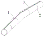
Fig. 1 is a schematic structural diagram of embodiment 1 of the present invention.
Fig. 2 is a schematic structural view of the single first wrapping member in fig. 1.
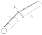
Fig. 3 is a schematic structural diagram of embodiment 2 of the present invention.
Fig. 4 is a schematic structural diagram of embodiment 3 of the present invention.
Fig. 5 is a schematic structural diagram of embodiment 4 of the present invention.
Detailed Description
The present invention will be described in further detail with reference to specific embodiments.
Example 1: referring to fig. 1-2, a device is strengthened at a break angle of a buried pipeline, wherein the device comprises a first cladding member 1 and a second cladding member 2 which are relatively fixedly arranged, a fixed connection structure is arranged between the first cladding member 1 and the second cladding member 2, and the first cladding member 1 and the second cladding member 2 can be fixed with each other by the fixed connection structure, two sections of intersected cylindrical inner cavities which are in a break angle are formed after the first cladding member 1 and the second cladding member 2 are relatively fixed, and the cylindrical inner cavities are matched with the pipeline appearance at the break angle of the buried pipeline to be strengthened.
When the sample device is used, the first coating piece and the second coating piece can be coated, installed and fixed at the folded angle position of the directly buried pipeline, and can assist in bearing stress generated when a part of the folded angle of the pipeline works, so that the folded angle is protected. Meanwhile, the device has the advantages of simple structure and convenience in implementation.
The cross sections of the first coating part 1 and the second coating part 2 are semicircular and form an outer cylinder bevel pipeline after being relatively fixed, and the relatively fixed positions of the first coating part 1 and the second coating part 2 are arranged along the length direction of the outer cylinder bevel pipeline.
Therefore, the device can be directly installed at the break angle position of the constructed direct-buried pipeline, and the corner position of the position bearing the maximum break angle stress is integrally formed, so that the force can be better borne. The first coating piece and the second coating piece are semi-cylindrical, and are more beneficial to self production and manufacturing. Of course, in practice, the first covering member and the second covering member may be a single member or a combined member, for example, the first covering member may be formed by splicing two or more members, and should be considered as still falling within the scope of the present application. Or the device has a structure that a plurality of cladding members are arranged in the circumferential direction or the axial direction as a whole, the device can also be regarded as a structure that the first cladding member and/or the second cladding member are formed by splicing a plurality of cladding members, and still fall into the protection scope of the present application.
Wherein, the first cladding member 1 and the second cladding member 2 are both formed by casting.
Therefore, the bearing can be manufactured conveniently and can bear force better.
The fixed connection structure comprises a butt joint edge 3 formed by extending the edge of a fixed position of each of the first covering piece and the second covering piece outwards along the radial direction of a cross section circle, and the butt joint edges of the first covering piece and the second covering piece are fixedly connected by a plurality of bolts 4 distributed along the axial direction after being jointed and butted (only part of the bolt structures are shown in the figure).
Therefore, the installation and construction are convenient, and the construction cost is low.
The outer edge 5 of the outer cylinder bevel pipeline formed after the first coating part 1 and the second coating part 2 are fixed relatively is in arc transition at a bevel position.
Therefore, stress concentration of the outer barrel angle folding pipeline formed on the outer side of the angle folding part per se can be better avoided, and the stress deformation resistance per se is improved.
The thickness of the outer barrel bevel pipeline formed after the first cladding member 1 and the second cladding member 2 are relatively fixed is gradually increased from two ends of the outer barrel bevel pipeline to a bevel.
Therefore, the strength of the outer barrel angle folding pipeline at the position of the angle can be better improved, and the capacity that the position is lower than the deformation is improved.
Example 2, see figure 3. The rest of the structure of this embodiment is the same as that of embodiment 1, except that no bolt is provided in this embodiment. In this embodiment, the fixed connection structure includes a butt-joint edge 3 formed by extending the edge of each of the first cladding member 1 and the second cladding member 2 radially outward along the cross-sectional circle at the opposite fixed position, and the butt-joint edges of the first cladding member and the second cladding member are fitted, butt-welded and fixed.
Thus, the construction cost is higher, but the connection strength is higher and more reliable.
Example 3, see figure 4.
The device of the embodiment is added with the following structure on the basis of the embodiment 1, and the first cladding member 1 and the second cladding member 2 are relatively fixed to form an outer cylinder bevel pipeline, and a circle of annular reinforcing ribs 6 are formed on the outer cylinder bevel pipeline in a mode that the outer cylinder bevel pipeline is outwards convex along the circumferential direction at the position of a bevel angle of the outer cylinder bevel pipeline.
Therefore, the strength of the outer barrel angle folding pipeline at the position of the angle can be better improved, and the capacity that the position is lower than the deformation is improved. The rest of the structure of this embodiment is the same as that of embodiment 1, and detailed description thereof is omitted.
Example 4, see figure 5.
This example differs from example 1 in that: the first coating piece 1 and the second coating piece 2 are in a straight cylinder shape with a circular cross section, and are relatively and fixedly connected along the position of a folded angle of the buried pipeline to be reinforced.
Therefore, the construction on the directly buried pipeline to be constructed is convenient.
In this embodiment, the butt joint ends of the first cladding member 1 and the second cladding member 2 are corresponding inclined surfaces and are butt jointed by the inclined flange 3 (the flange butt joint bolt is not shown in the figure).
Like this, convenient fixed and rely on the ring flange of butt joint end, greatly improved the protection intensity of dog-ear department position, improved dog-ear department position and resisted the outside ability that warp that inside directly buried pipeline received extrusion stress to produce. The rest of the structure of this embodiment is the same as that of embodiment 1, and detailed description thereof is omitted.
Claims (10)
1. The utility model provides a device is reinforceed at buried pipeline dog-ear which characterized in that, includes first cladding piece and the second cladding piece of relatively fixed setting, is provided with fixed connection structure between first cladding piece and the second cladding piece and can relies on fixed connection structure to realize fixing each other, first cladding piece and second cladding piece form two sections crossing tube-shape inner chambers that are the dog-ear after relatively fixed, and this tube-shape inner chamber and the buried pipeline dog-ear that treats the reinforceing pipeline appearance match.
2. The apparatus as claimed in claim 1, wherein the first and second wrapping members have a semi-circular cross-section and are fixed to each other to form an outer cylinder angle pipe, and the relative fixing positions of the first and second wrapping members are arranged along the length direction of the outer cylinder angle pipe.
3. The apparatus of claim 2, wherein the first and second cladding members are cast.
4. The apparatus of claim 2, wherein the fixed connection structure comprises a butt joint edge formed by extending the edge of the first covering member and the edge of the second covering member radially outward along the cross-sectional circle at the opposite fixed positions, and the butt joint edges of the first covering member and the second covering member are fixedly connected by a plurality of bolts distributed along the axial direction after being abutted and jointed.
5. The apparatus of claim 2, wherein the fixed connection structure comprises abutting edges formed by extending the first covering member and the second covering member radially and outwardly along the cross-sectional circle at the edges of the fixed positions, and the abutting edges of the first covering member and the second covering member are fixed by butt welding.
6. The apparatus as claimed in claim 2, wherein the first and second coating members are fixed relative to each other to form an outer cylindrical angle pipe, and the outer edges of the angle pipe at the angle position are in arc transition.
7. The apparatus as claimed in claim 2, wherein the first and second coating members are fixed to form an outer cylindrical angle pipe with a thickness gradually increasing from two ends to the angle.
8. The apparatus as claimed in claim 2, wherein the first and second covering members are fixed relative to each other to form an outer cylindrical angle pipe, and a ring-shaped reinforcing rib is formed at the position of the angle of the pipe and is protruded outwards along the circumferential direction.
9. The apparatus according to claim 1, wherein the first covering member and the second covering member are cylindrical members having a circular cross-section and are fixedly connected to each other along the bend of the buried pipeline to be reinforced.
10. The apparatus of claim 9, wherein the butt joint ends of the first cladding member and the second cladding member are inclined surfaces and butt joint is achieved by means of an inclined flange.
Priority Applications (1)
| Application Number | Priority Date | Filing Date | Title |
|---|---|---|---|
| CN202122347507.2U CN215674173U (en) | 2021-09-27 | 2021-09-27 | Device is reinforceed to directly buried pipeline dog-ear |
Applications Claiming Priority (1)
| Application Number | Priority Date | Filing Date | Title |
|---|---|---|---|
| CN202122347507.2U CN215674173U (en) | 2021-09-27 | 2021-09-27 | Device is reinforceed to directly buried pipeline dog-ear |
Publications (1)
| Publication Number | Publication Date |
|---|---|
| CN215674173U true CN215674173U (en) | 2022-01-28 |
Family
ID=79966589
Family Applications (1)
| Application Number | Title | Priority Date | Filing Date |
|---|---|---|---|
| CN202122347507.2U Active CN215674173U (en) | 2021-09-27 | 2021-09-27 | Device is reinforceed to directly buried pipeline dog-ear |
Country Status (1)
| Country | Link |
|---|---|
| CN (1) | CN215674173U (en) |
-
2021
- 2021-09-27 CN CN202122347507.2U patent/CN215674173U/en active Active
Similar Documents
| Publication | Publication Date | Title |
|---|---|---|
| CN201462207U (en) | Sealing device between protective well through hole and underground pipeline | |
| CN103470908B (en) | For the distance sleeve device of the in-service permanent reparation of submarine pipeline | |
| CN112901873A (en) | Direct-buried sleeve compensator | |
| CN109058635B (en) | Prefabricated thermal insulation double-layer elbow and preparation method thereof | |
| TWM623223U (en) | connection device | |
| CN214579550U (en) | Direct-buried sleeve compensator | |
| CN202182285U (en) | Ultra-large diameter diversion pressure steel pipe expansion device of hydropower station | |
| CN105240627A (en) | Prefabricated assembled steel-concrete composite steel pipe and a manufacturing method thereof | |
| CN211315325U (en) | Direct-buried laying steam pipeline structure | |
| CN215891450U (en) | Reinforced direct-buried bevel pipe fitting | |
| CN211525846U (en) | Hot rod type pipe support with fixed efficient heat insulation pipe support | |
| CN215522401U (en) | Tee joint suitable for directly-buried pipeline | |
| CN215522402U (en) | Internal reinforced three-way joint | |
| CN216692489U (en) | Reinforced structure in corrugated pipe and corrugated pipe assembly | |
| CN214305819U (en) | Double-layer pipeline tee joint | |
| CN216201539U (en) | Disposable corrugated compensator | |
| CN210372529U (en) | Auxiliary anti-falling device for half joint | |
| CN117966897A (en) | Round steel tube concrete column staggered-layer unequal-height special-shaped beam column node and construction method | |
| CN210141378U (en) | Direct-buried heat supply pipeline with different limiting and compensating structures for water supply and return pipelines | |
| CN212338384U (en) | Anti-rotation support leg of buried pipeline | |
| CN223648813U (en) | A reinforcement structure for welded joints of carbon steel pipes | |
| CN108253203A (en) | Pipeline and its component | |
| CN223399509U (en) | Corrosion-resistant steel pipe | |
| CN215763888U (en) | a pipe connector | |
| CN217234832U (en) | Enhanced anti-corrosion metal compensator |
Legal Events
| Date | Code | Title | Description |
|---|---|---|---|
| GR01 | Patent grant | ||
| GR01 | Patent grant | ||
| TR01 | Transfer of patent right |
Effective date of registration: 20231011 Address after: 064100 Hebei Tangshan City Yutian County Hou Hu industrial gathering area Patentee after: TANGSHAN XINGBANG PIPE CONSTRUCTION EQUIPMENT Co.,Ltd. Address before: 030006 Zhongchuang space of qingqingchuang company, block a, 529 South Central Street, Taiyuan Xuefu Park, comprehensive reform demonstration zone, Taiyuan City, Shanxi Province Patentee before: SHANXI LIGONG HONGRI ENERGY SAVING SERVICE Co.,Ltd. |
|
| TR01 | Transfer of patent right |