Simple and easy pole device that erects
Technical Field
The utility model belongs to the technical field of power grid construction, and particularly relates to a simple pole erecting device.
Background
At present, the electric wire netting construction scale is expanding day by day, and power machinery construction such as crane, trailer, tractor has all been used to most occasions, has greatly improved the operating efficiency. However, the large-scale machinery cannot be found due to the limitation of fields and environmental restrictions, and power machines such as cranes, trailers and the like are inconvenient to enter the fields and mountainous areas where lines need to be built. The operation of the hack lever only depends on manpower, the operation difficulty is higher, and under the condition without a power machine, the operation efficiency is low due to the fact that the operation is purely dependent on the manpower, and therefore improvement is needed urgently.
SUMMERY OF THE UTILITY MODEL
In order to solve the technical problems, the utility model provides the following technical scheme:
a simple pole erecting device comprises a sliding mechanism and a traction mechanism which are respectively arranged on two sides of a pole pit, and a protection piece which is arranged in the pole pit and used for protecting the pole pit, wherein the protection piece is arranged on the opposite side of the sliding mechanism, the sliding mechanism comprises a bottom plate and a mounting plate which is connected to the bottom plate through a support in an inclined mode, the included angle between the mounting plate and the horizontal plane is 45-60 degrees, a first walking mechanism and a first fixing mechanism are arranged below the bottom plate, a sliding rod groove used for placing a pole is formed in the top of the mounting plate, the lower end of the sliding rod groove corresponds to the pole pit and is hinged with a baffle which can be opened and closed, a hanging lug is arranged at the top end of the pole, the traction mechanism comprises a fixing seat and a rotating disc, a second walking mechanism and a second fixing mechanism are arranged below the fixing seat, the rotating disc is supported above the fixing seat through a rotating disc frame, and a traction rope is wound on the rotating disc, the one end that the carousel was kept away from to the haulage rope is connected with the hangers on pole top through the couple, the carousel rotates with the carousel frame through first pivot to be connected, and the one end coaxial coupling that the carousel was kept away from to first pivot has drive gear, drive gear's below is equipped with the hand actuating mechanism that can drive gear rotation.
Preferably, the protection piece includes the guard plate that the semicircular in shape set up, guard plate internal diameter and pole external diameter phase-match, the internal diameter phase-match of guard plate external diameter and pole hole, one side that the pole was kept away from to the guard plate is equipped with the backup pad of fixing on pole hole edge, be equipped with third fixed establishment in the backup pad, through setting up the protection piece, can get into the in-process in pole hole at the pole and play the safety protection effect to the pole hole, play vertical guide effect to the pole simultaneously.
Preferably, the third fixing mechanism comprises a third ground inserting cone which is arranged on the supporting plate in a threaded penetrating mode, a third rotating handle is arranged at the top of the third ground inserting cone, the third ground inserting cone can be adjusted up and down conveniently through the third rotating handle, and the supporting plate can be effectively fixed on the rod pit edge.
Preferably, the first travelling mechanism comprises four first travelling wheels symmetrically arranged on two sides of the bottom plate, the first fixing mechanism comprises four first adjusting blocks symmetrically connected to two sides of the bottom plate, each first adjusting block is connected with a first ground inserting cone in a threaded manner, and a first rotating handle is arranged at the top of the first ground inserting cone. The sliding mechanism can be conveniently and flexibly moved by arranging the first travelling wheel, and the first inserting cone can be adjusted up and down by rotating the first handle, so that the bottom plate can be firmly fixed on the ground.
Preferably, the second running gear includes that the symmetry sets up four second walking wheels in the fixing base both sides, second fixed establishment includes four second regulating blocks of symmetric connection in the fixing base both sides, every threaded connection has the second to insert ground awl on the second regulating block, the top that the second inserted ground awl is equipped with second rotating handle. The fixing seat can be conveniently and flexibly moved by arranging the second travelling wheel, the second travelling wheel can be adjusted up and down by inserting the second travelling wheel into the ground cone through the second rotating handle, and the fixing seat is conveniently and firmly fixed on the ground.
Preferably, hand actuating mechanism is including locating the drive gear below and the wave gear of being connected with the drive gear meshing, wave gear rotates through the second pivot and connects at the carousel frame, and wave gear keeps away from one side off-centre of carousel frame and is provided with the handle of shaking, wave gear's diameter is less than drive gear's diameter, through hand actuating mechanism, makes the carousel rotatory, and then draws the pole through the haulage rope and follow swift current pole groove gliding and get into the pole hole, simultaneously, falls into the in-process in pole hole at the pole, plays directional application of force and safety limiting's effect.
Preferably, the transmission ratio of the rocking gear to the transmission gear is 3-6, and the transmission gear rotates at a low speed through manual rotation of the rocking gear, so that the turntable is driven to rotate, and the effect of saving power is achieved.
Preferably, the lower part of baffle is connected with the bottom hinge of swift current pole groove through the hinge, and the both sides of baffle rotate respectively and are connected with the cardboard, the expansion end of cardboard is equipped with the draw-in groove, the both sides cell wall of swift current pole groove corresponds outward and is equipped with the kelly corresponding with the cardboard, kelly and draw-in groove phase-match make cardboard and kelly quick joint or break away from through the draw-in groove, make things convenient for opening and shutting of baffle, are favorable to the swift current of pole to put and spacing.
Preferably, a push-pull handle is arranged on the support at one end, far away from the rod pit, of the sliding mechanism, so that the sliding mechanism can be conveniently pushed and pulled manually to move.
The utility model also comprises other devices or components which can ensure the simple pole erecting device to be normally used and are conventional technical means in the field; in addition, the devices and components not limited in this invention are all adopted by the conventional technical means in the field.
The utility model discloses an operating principle is, during the use, before the swift current mechanism gets into the construction site, close the baffle of the low side in swift current pole groove earlier, put into swift current pole groove with the pole through power machinery, then the manual work pulls swift current mechanism, make swift current mechanism get into the construction site, the low side that makes swift current pole groove is corresponding with the pole hole, then make swift current mechanism fix the one side in the pole hole through first fixed establishment, put into the pole hole with the protection piece, and make the protection piece place for swift current mechanism, the fixed drive mechanism in one side of keeping away from swift current mechanism in the pole hole, and make the haulage rope be connected with the hangers on pole top through the couple, open the baffle, make the pole slide along swift current pole groove, then pass through hand actuating mechanism if the pole does not slide, it is rotatory to drive the carousel. Exert pulling force to the pole through the haulage rope, can pull the pole gliding, when the lower extreme of pole supports and leans on the protection piece, it is rotatory to continue through hand actuating mechanism drive carousel, makes the pole change with the conflict angle of protection piece, and then makes the pole slowly slide into in the pole hole along the protection piece. Be 45 ~ 60 slope connections on the bottom plate with the mounting panel through the support, make things convenient for the pole through the dead weight along swift current pole groove gliding, can effectively reduce artifical intensity of labour, improve the pole and erect efficiency.
Compared with the prior art, the utility model has the following beneficial effects: under the conditions of being confined to a field and having no power machine, the electric pole can be flexibly moved and erected by manpower through the device, so that the manual labor intensity is favorably reduced, and the operation efficiency is improved.
Drawings
The utility model is further illustrated with reference to the following figures and examples.
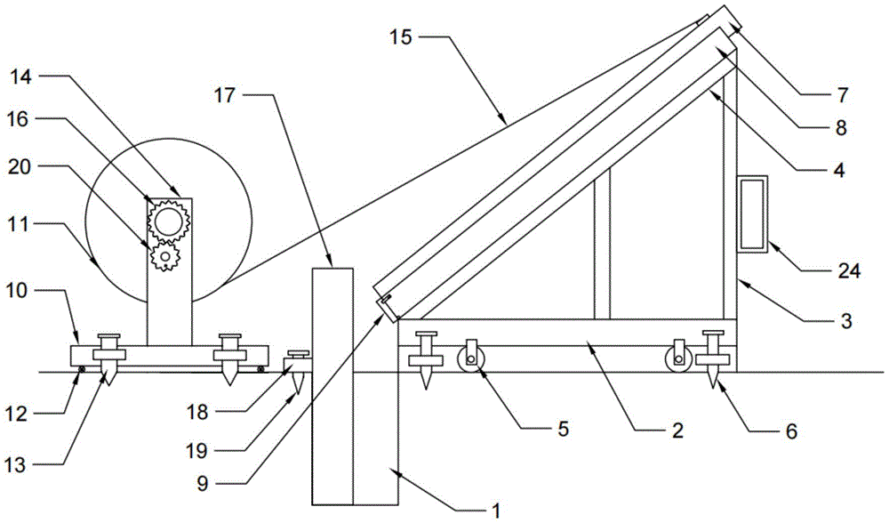
Fig. 1 is a schematic view of the overall structure of the present invention in the embodiment.
Fig. 2 is a side view schematically showing a partial structure of the traction mechanism in the embodiment.
Fig. 3 is a schematic top view of the protection device of fig. 1.
Fig. 4 is a schematic perspective view of the chute of fig. 1.
Fig. 5 is an enlarged schematic view of the structure of the G-section in fig. 4.
Detailed Description
The present invention will be described more clearly with reference to the accompanying drawings, which are included to illustrate and not to limit the present invention. All other embodiments, which can be obtained by those skilled in the art without any inventive step based on the embodiments of the present invention, should be included in the scope of the present invention.
Examples
As shown in fig. 1 to 5, the utility model provides a simple pole erecting device, comprising a sliding mechanism and a traction mechanism respectively arranged at two sides of a pole pit 1, and a protection piece arranged in the pole pit 1 for protecting the pole pit, wherein the protection piece is arranged at the opposite side of the sliding mechanism, the sliding mechanism comprises a bottom plate 2 and a mounting plate 4 obliquely connected to the bottom plate 2 through a bracket 3, the included angle between the mounting plate 4 and the horizontal plane is 60 degrees, a first traveling mechanism 5 and a first fixing mechanism 6 are arranged below the bottom plate 2, a sliding groove 8 for placing an electric pole 7 is arranged at the top of the mounting plate 4, the lower end of the sliding groove 8 is arranged corresponding to the pole pit 1, a baffle 9 capable of opening and closing is hinged at the lower end of the sliding groove 8, a hanging lug is arranged at the top end of the electric pole 7, the traction mechanism comprises a fixed seat 10 and a rotating disc 11, a second traveling mechanism 12 and a second fixing mechanism 13 are arranged below the fixed seat 10, the rotary table 11 is supported above the fixing seat 10 through the rotary table frame 14, a traction rope 15 is wound on the rotary table 11, one end, far away from the rotary table 11, of the traction rope 15 is connected with a hanging lug on the top end of the electric pole 7 through a hook, the rotary table 11 is rotatably connected with the rotary table frame 14 through a first rotating shaft, one end, far away from the rotary table 11, of the first rotating shaft is coaxially connected with a transmission gear 16, and a hand-cranking driving mechanism capable of driving the transmission gear 16 to rotate is arranged below the transmission gear 16.
The protection piece includes the guard plate 17 that the semicircular in shape set up, the internal diameter of guard plate 17 and the external diameter phase-match of pole 7, the external diameter of guard plate 17 and the internal diameter phase-match of pole hole 1, one side that pole 7 was kept away from to guard plate 17 is equipped with the backup pad 18 of fixing on pole hole 1 hole edge, be equipped with third fixed establishment 19 in the backup pad 18, through setting up the protection piece, can get into the in-process of pole hole 1 at pole 7 and play the safety protection effect to pole hole 1, play vertical guide effect to pole 7 simultaneously. The third fixing mechanism 19 comprises a third ground inserting cone which is threaded on the supporting plate 18, a third rotating handle is arranged at the top of the third ground inserting cone, and the third ground inserting cone can be adjusted up and down conveniently through the third rotating handle, so that the supporting plate 18 can be effectively fixed on the pit edge of the rod pit 1.
First running gear 5 includes that the symmetry sets up four first travelling wheels in bottom plate 2 both sides, first fixed establishment 6 includes four first regulating blocks of symmetric connection in bottom plate 2 both sides, every threaded connection has first ground awl of inserting on the first regulating block, the first top of inserting ground awl is equipped with first rotating handle. The sliding mechanism can be conveniently and flexibly moved by arranging the first travelling wheel, and the first inserting cone can be adjusted up and down by rotating the first handle, so that the bottom plate 2 is conveniently and firmly fixed on the ground. Second running gear 12 sets up four second walking wheels at fixing base 10 both sides including the symmetry, second fixed establishment 13 includes four second regulating blocks of symmetric connection in fixing base 10 both sides, every threaded connection has the second to insert ground awl on the second regulating block, the top that the second inserted ground awl is equipped with the second rotating handle. The fixing seat 10 can be conveniently and flexibly moved by arranging the second travelling wheel, the second ground cone can be vertically adjusted by rotating the handle, and the fixing seat 10 is conveniently and firmly fixed on the ground.
Hand actuating mechanism is including locating drive gear 16 below and with the wave gear 20 that drive gear 16 meshing is connected, wave gear 20 rotates through the second pivot and connects at carousel frame 14, and wave gear 20 and keep away from one side eccentric settings of carousel frame 14 and wave handle 21, the diameter of wave gear 20 is less than drive gear 16's diameter, and waves the drive ratio of gear 20 and drive gear 16 and be 6, through hand actuating mechanism, makes carousel 11 rotatory, and then through haulage rope 15 pull pole 7 along smooth pole groove 8 gliding and get into pole pit 1 in, simultaneously, fall into pole pit 1 at pole 7 in-process, play directional application of force and safety spacing effect, simultaneously, owing to adopted great drive ratio, make the operation more laborsaving.
The lower part of baffle 9 passes through the hinge and is connected with the bottom hinge of swift current pole groove 8, and the both sides of baffle 9 rotate respectively and be connected with cardboard 22, the expansion end of cardboard 22 is equipped with the draw-in groove, the both sides cell wall of swift current pole groove 8 corresponds outward and is equipped with the kelly 23 corresponding with cardboard 22, kelly 23 and draw-in groove phase-match make cardboard 22 and kelly 23 quick joint or break away from through the draw-in groove, make things convenient for opening and shutting of baffle 9, are favorable to the swift current of pole 7 to be put and spacing. The push-pull handle 24 is arranged on the support 3 at one end, far away from the rod pit 1, of the sliding mechanism, so that the sliding mechanism can be conveniently pushed and pulled manually to move.
The utility model discloses an operating principle is, in the use, before the swift current mechanism gets into the construction site, close the baffle 9 of the low side of swift current pole groove 8 earlier, put into swift current pole groove 8 with pole 7 through power machinery, then the manual work pulls swift current mechanism, make swift current mechanism get into the construction site, make the low side of swift current pole groove 8 and pole hole 1 corresponding, then make swift current mechanism fix in one side of pole hole 1 through first fixed establishment 6, put into pole hole 1 with the protection piece, and make the protection piece place for swift current mechanism, it fixes drive mechanism to keep away from one side of swift current mechanism in pole hole 1, and make haulage rope 15 be connected with the hangers on pole 7 top through the couple, open baffle 9, make pole 7 slide along swift current pole groove 8, if pole 7 does not slide then through hand actuating mechanism, it is rotatory to drive carousel 11. Exert pulling force to pole 7 through haulage rope 15, can pull pole 7 gliding, when the lower extreme of pole 7 supports and leans on the protection piece, continue to rotate through hand actuating mechanism drive carousel 11, make the conflict angle of pole 7 with the protection piece change, and then make pole 7 follow the protection piece and slowly slide into in the pole hole 1. Be 60 slope connections with mounting panel 4 through support 3 on bottom plate 2, make things convenient for pole 7 to slide along swift current pole groove 8 through the dead weight, can effectively reduce artifical intensity of labour, improve the efficiency of erectting of pole 7.
Having described embodiments of the present invention, the foregoing description is intended to be exemplary, not exhaustive, and not limited to the disclosed embodiments. Many modifications and variations will be apparent to those of ordinary skill in the art without departing from the scope and spirit of the illustrated embodiments.