CN215667438U - Large-flux water purifier - Google Patents
Large-flux water purifier Download PDFInfo
- Publication number
- CN215667438U CN215667438U CN202122351343.0U CN202122351343U CN215667438U CN 215667438 U CN215667438 U CN 215667438U CN 202122351343 U CN202122351343 U CN 202122351343U CN 215667438 U CN215667438 U CN 215667438U
- Authority
- CN
- China
- Prior art keywords
- water
- filter element
- membrane filter
- branch
- membrane
- Prior art date
- Legal status (The legal status is an assumption and is not a legal conclusion. Google has not performed a legal analysis and makes no representation as to the accuracy of the status listed.)
- Active
Links
- XLYOFNOQVPJJNP-UHFFFAOYSA-N water Substances O XLYOFNOQVPJJNP-UHFFFAOYSA-N 0.000 title claims abstract description 400
- 239000012528 membrane Substances 0.000 claims abstract description 164
- 230000004907 flux Effects 0.000 claims abstract description 40
- 238000001914 filtration Methods 0.000 claims abstract description 39
- 239000002351 wastewater Substances 0.000 claims description 65
- 238000000926 separation method Methods 0.000 claims description 19
- 239000008213 purified water Substances 0.000 claims description 17
- 239000002131 composite material Substances 0.000 claims description 9
- 239000008399 tap water Substances 0.000 claims description 8
- 235000020679 tap water Nutrition 0.000 claims description 8
- 238000000746 purification Methods 0.000 description 7
- 238000011045 prefiltration Methods 0.000 description 5
- 230000000903 blocking effect Effects 0.000 description 3
- 238000010586 diagram Methods 0.000 description 3
- 238000001223 reverse osmosis Methods 0.000 description 3
- 230000009286 beneficial effect Effects 0.000 description 2
- 235000008331 Pinus X rigitaeda Nutrition 0.000 description 1
- 235000011613 Pinus brutia Nutrition 0.000 description 1
- 241000018646 Pinus brutia Species 0.000 description 1
- 238000004891 communication Methods 0.000 description 1
- 230000000694 effects Effects 0.000 description 1
- 239000012535 impurity Substances 0.000 description 1
- 238000000034 method Methods 0.000 description 1
- 238000012986 modification Methods 0.000 description 1
- 230000004048 modification Effects 0.000 description 1
- 238000007789 sealing Methods 0.000 description 1
- 239000000126 substance Substances 0.000 description 1
- 238000006467 substitution reaction Methods 0.000 description 1
- 239000013589 supplement Substances 0.000 description 1
Images


Landscapes
- Separation Using Semi-Permeable Membranes (AREA)
Abstract
The utility model discloses a large-flux water purifier which comprises a case, a front filter element, a first RO membrane filter element, a second RO membrane filter element and a water path component, wherein the case is provided with a water inlet and a water outlet; the preposed filter element, the first RO membrane filter element and the second RO membrane filter element are respectively arranged in the case; the water path assembly is arranged in the case and is used for communicating the initial filtered water outlet end of the front filter element with the water inlet ends of the first RO membrane filter element and the second RO membrane filter element respectively; the pure water end of first RO membrane filter core and second RO membrane filter core joins, just the pure water that first RO membrane filter core and second RO membrane filter core produced passes through water route subassembly discharge machine case. The large-flux water purifier increases the total flux of the filtering system in a mode of two RO membrane filter elements with smaller flux connected in parallel, so that the large-flux filtering system can filter more pure water in unit time. When the first RO membrane filter element or the second RO membrane filter element is polluted or the service life is up to the end, only the corresponding first RO membrane filter element or the corresponding second RO membrane filter element needs to be replaced.
Description
Technical Field
The utility model relates to the field of water purifiers, in particular to a large-flux water purifier.
Background
At present, tap water contains a lot of substances which are not beneficial to health, so more and more people can set up water purifying equipment at home to filter the tap water. Current water purification unit mainly relies on reverse osmosis membrane (RO membrane) to filter the running water, in order to filter enough pure water in time, all can set up big flux reverse osmosis filter core in the water purification unit, and big flux is 1000G or more.
In prior art water purification unit, when the filter core appears polluting or the life-span is up to date, need to change the whole filter core of purifier, the flow of purifier is bigger more usually, and the replacement cost of filter core just is higher more, and consequently big flux purifier filter core replacement cost is just higher. And single filter core water purification unit is relatively poor to quality of water environment or to the user that produces the higher requirement of water, and its mode of producing water does not satisfy the requirement.
SUMMERY OF THE UTILITY MODEL
The utility model aims to provide a large-flux water purifier to solve the problem that the filter element of the large-flux water purifier is high in replacement cost.
In order to achieve the purpose, the utility model adopts the following technical scheme:
the utility model provides a large-flux water purifier which comprises a case, a front filter element, a first RO membrane filter element, a second RO membrane filter element and a water path component, wherein the case is provided with a water inlet and a water outlet;
the preposed filter element, the first RO membrane filter element and the second RO membrane filter element are respectively arranged in the case;
the water path assembly is arranged in the case and is used for communicating the initial filtered water outlet end of the front filter element with the water inlet ends of the first RO membrane filter element and the second RO membrane filter element respectively; the pure water end of first RO membrane filter core and second RO membrane filter core joins, just the pure water that first RO membrane filter core and second RO membrane filter core produced passes through water route subassembly discharge machine case.
In the large-flux water purifier, the preposed filter element and the first RO membrane filter element are combined into a composite filter element, and the waste water end of the first RO membrane filter element is communicated with the water inlet end of the preposed filter element in a one-way mode.
In the large-flux water purifier, the preposed filter element comprises an upper cover, a filter element structure, a connecting cover and a separating pipe;
the upper cover is arranged at the upper end of the filter element structure, and the connecting cover is arranged at the lower end of the filter element structure; a hollow water filtering cavity is arranged in the filter element structure; the connecting cover is provided with a through hole communicated with the water filtering cavity, and the upper cover is provided with a water outlet pipe communicated with the water filtering cavity; the lower end of the separation pipe is sleeved in the through hole, and the upper end of the separation pipe extends out of the water outlet pipe;
the first RO membrane filter element comprises an inner shell, a filter membrane structure arranged in the inner shell, a water collecting pipe and a flow guide pipe;
the upper end of the inner shell is connected with the connecting cover, the lower end of the inner shell is provided with a waste water port, and a waste water check valve is arranged in the waste water port; the filter membrane structure is sleeved on the outer side of the water collecting pipe, the lower end of the water collecting pipe is fixed on the inner shell, and a water plugging block is arranged at the near end of the lower end of the water collecting pipe; the upper end of the water collecting pipe is inserted into the separation pipe; the lower end of the flow guide pipe is sleeved in the water collecting pipe, and the upper end of the flow guide pipe extends out of the separation pipe.
In the large-flux water purifier, the composite filter element further comprises a filter cover and a shell;
a raw water cavity is formed in the shell, the preposed filter element and the first RO membrane filter element are arranged in the raw water cavity, and the waste water port is communicated with the raw water cavity;
the filter cover is detachably connected to the shell; the bottom surface of the filter cover is provided with a concave cavity, the concave cavity is provided with a first water-proof ring, a second water-proof ring and a third water-proof ring, the first water-proof ring surrounds the periphery of the second water-proof ring, and the second water-proof ring surrounds the periphery of the third water-proof ring;
the upper end of the water outlet pipe is sleeved in the first waterproof ring, the upper end of the separation pipe is sleeved in the second waterproof ring, and the upper end of the flow guide pipe is sleeved in the third waterproof ring;
the inner wall of the first water-isolating ring, the outer wall of the second water-isolating ring, the inner wall of the water outlet pipe and the outer wall of the separating pipe form a water outlet cavity, and the water outlet cavity is communicated with the water filtering cavity;
the inner wall of the second water-proof ring, the outer wall of the third water-proof ring, the inner wall of the separation pipe and the outer wall of the flow guide pipe form a primary water filtering cavity;
and the inner wall of the third water-isolating ring forms a pure water cavity, and the pure water cavity is communicated with the flow guide pipe.
In the large-flux water purifier, the filter cover is provided with a raw water inlet, an initial filtered water outlet, an initial filtered water inlet and a pure water outlet;
the raw water inlet is communicated with the raw water cavity; the primary filter water outlet is communicated with the water outlet cavity; the primary filter water inlet is communicated with the primary filter water cavity; the pure water outlet is communicated with the pure water cavity.
In the large-flux water purifier, the water path component comprises a water path plate, a water inlet valve, a booster pump and a high-pressure switch;
the water path plate comprises a connecting seat, a raw water branch, a primary filter water branch, a pressurizing branch, a pure water branch and a wastewater branch, wherein the raw water branch, the primary filter water branch, the pressurizing branch, the pure water branch and the wastewater branch are respectively arranged on the connecting seat;
one end of the raw water branch is communicated with the water inlet end of the front filter element, and the other end of the raw water branch forms a tap water interface;
one end of the primary water filtering branch is communicated with the water outlet end of the front filter element, the other end of the primary water filtering branch is communicated with the water inlet end of the water inlet valve, and the water outlet end of the water inlet valve is communicated with the water inlet end of the booster pump;
the pressurizing branch is used for communicating the water inlet ends of the first RO membrane filter element and the second RO membrane filter element with the water outlet end of the pressurizing pump;
one end of the pure water branch joins the pure water ends of the first RO membrane filter element and the second RO membrane filter element, and the other end of the pure water branch forms a pure water interface;
one end of the wastewater branch is communicated with the wastewater end of the second RO membrane filter core, and the other end of the wastewater branch forms a wastewater interface;
the high-pressure switch is arranged between the pure water end of the second RO membrane filter core and the pure water interface, and the high-pressure switch is electrically connected with the water inlet valve and the booster pump.
In the large-flux water purifier, a first check valve is arranged between the purified water end of the first RO membrane filter element and the purified water interface;
a second check valve is arranged between the pure water end of the second RO membrane filter element and the high-pressure switch;
the waste water branch is provided with a waste water proportional valve.
In the large-flux water purifier, the flux of the booster pump is 800 gallons per hour, the flux of the first RO membrane cartridge is 300 gallons per hour, and the flux of the second RO membrane cartridge is 700 gallons per hour.
One technical scheme in the utility model can have the following beneficial effects:
the large-flux water purifier uses two RO membrane filter elements connected in parallel, and the total flux of the filter system is increased in a mode of two RO membrane filter elements connected in parallel and having smaller flux, so that the large-flux filter system can filter more pure water in unit time. And first RO membrane filter core and second RO membrane filter core are independent each other, appear polluting or when life-span extremely when first RO membrane filter core or second RO membrane filter core, only need change corresponding first RO membrane filter core or second RO membrane filter core can, avoid current big flux filtration system need change the condition of whole big flux filter core, not only realize the purpose of big flux water purification, still practice thrift the cost of changing big flux filter core.
Drawings
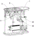
FIG. 1 is a schematic diagram of the internal structure of one embodiment of the present invention;
FIG. 2 is a schematic diagram of the overall structure of one embodiment of the present invention;
FIG. 3 is a schematic cross-sectional view of a composite filter element according to one embodiment of the present invention;
FIG. 4 is an enlarged view of a portion of FIG. 3 at A;
FIG. 5 is a schematic diagram of a filter lid according to one embodiment of the present invention;
FIG. 6 is a schematic view of the structure of the waterway plate in one embodiment of the present invention;
in the drawings: the device comprises a case 1, a composite filter element 2, a second RO membrane filter element 3 and a water path component 4; a tap water interface 5, a purified water interface 6 and a wastewater interface 7;
a raw water cavity 11, a water outlet cavity 12, a primary filter cavity 13 and a pure water cavity 14; the device comprises a front filter element 21, a first RO membrane filter element 22, a filter cover 23 and a shell 24; a water channel plate 41, a water inlet valve 42, a booster pump 43, a high-pressure switch 44, a first check valve 45, a second check valve 46 and a wastewater proportional valve 47;
an upper cover 211, a filter element structure 212, a connecting cover 213 and a separating pipe 214; an inner shell 221, a filter membrane structure 222, a water collecting pipe 223 and a guide pipe 224; a cavity 231, a first water-proof ring 232, a second water-proof ring 233 and a third water-proof ring 234; a raw water inlet 235, an initial filtered water outlet 236, an initial filtered water inlet 237, and a pure water outlet 238; a connecting seat 411, a raw water branch 412, a primary water filtering branch 413, a pressurizing branch 414, a pure water branch 415 and a wastewater branch 416;
a water outlet pipe 2111 and a water filtering cavity 2121; a waste water check valve 2211 and a water blocking block 2231.
Detailed Description
Reference will now be made in detail to embodiments of the present invention, examples of which are illustrated in the accompanying drawings, wherein like or similar reference numerals refer to the same or similar elements or elements having the same or similar function throughout. The embodiments described below with reference to the accompanying drawings are illustrative only for the purpose of explaining the present invention, and are not to be construed as limiting the present invention.
In the description of the present invention, it is to be understood that the terms "upper", "lower", "vertical", "horizontal", "inner", "outer", etc. indicate orientations or positional relationships based on those shown in the drawings, and are only for convenience of description and simplicity of description, but do not indicate or imply that the referred device or element must have a specific orientation, be constructed and operated in a specific orientation, and thus, should not be construed as limiting the present invention. Furthermore, features defined as "first" and "second" may explicitly or implicitly include one or more of the features for distinguishing between descriptive features, non-sequential, non-trivial and non-trivial.
In the description of the present invention, "a plurality" means two or more unless otherwise specified.
In the description of the present invention, it should be noted that, unless otherwise explicitly specified or limited, the terms "mounted," "connected," and "connected" are to be construed broadly, e.g., as meaning either a fixed connection, a removable connection, or an integral connection; can be mechanically or electrically connected; they may be connected directly or indirectly through intervening media, or they may be interconnected between two elements. The specific meanings of the above terms in the present invention can be understood in specific cases to those skilled in the art.
Referring to fig. 1 to 6, the present invention provides a large flux water purifier, which includes a case 1, a front filter element 21, a first RO membrane filter element 22, a second RO membrane filter element 3, and a water path assembly 4;
the preposed filter element 21, the first RO membrane filter element 22 and the second RO membrane filter element 3 are respectively arranged in the case 1;
the water path component 4 is arranged in the machine box, and the water path component 4 is used for communicating the primary filtered water outlet end of the front filter element 21 with the water inlet ends of the first RO membrane filter element 22 and the second RO membrane filter element 3 respectively; the pure water ends of the first RO membrane filter element 22 and the second RO membrane filter element 3 are joined, and the pure water generated by the first RO membrane filter element 22 and the second RO membrane filter element 3 is discharged out of the case 1 through the water path component 4.
The large-flux water purifier uses two RO membrane filter elements connected in parallel, and the total flux of the filter system is increased in a mode of two RO membrane filter elements connected in parallel and having smaller flux, so that the large-flux filter system can filter more pure water in unit time. And first RO membrane filter core 22 and second RO membrane filter core 3 are independent each other, appear polluting or when the life-span arrives in first RO membrane filter core 22 or second RO membrane filter core 3, only need to change corresponding first RO membrane filter core 22 or second RO membrane filter core 3 can, avoid current big flux filtration system need change the condition of whole big flux filter core, not only realize the purpose of big flux water purification, still practice thrift the cost of changing the big flux filter core.
The pre-filter element 21 plays a role of pre-filtering, can prevent impurities in tap water from attaching to the RO membrane and affecting the work of the first RO membrane filter element 22 or the second RO membrane filter element 3, and can prolong the service life of the first RO membrane filter element 22 and the second RO membrane filter element 3.
The water which is not filtered by the large-flux filtering system is raw water, the raw water enters the preposed filter element 21, and the preposed filter element 21 filters the raw water into primary filter water; after the primary filter water is discharged from the water outlet end of the pre-filter element 21 to the water path component 4, the water path component 4 pumps the primary filter water to the first RO membrane filter element 22 or the second RO membrane filter element 3 respectively, and the first RO membrane filter element 22 or the second RO membrane filter element 3 carries out reverse osmosis filtration; first RO membrane filter core 22 and second RO membrane filter core 3 all can filter into the pure water with the initial drainage, and the pure water end of first RO membrane filter core 22 and second RO membrane filter core 3 joins, and the pure water passes through water route subassembly 4 big flux filtration system of discharge.
Further, leading filter core 21 and first RO membrane filter core 22 make up into composite filter core 2, the waste water end of first RO membrane filter core 22 and the one-way intercommunication of the end of intaking of leading filter core 21.
By adopting the structure, the wastewater generated by the filtration of the first RO membrane filter element 22 is mixed with the raw water and enters the preposed filter element 21 again for filtration, the wastewater generated by the first RO membrane filter element 22 is fully utilized, the proportion between the wastewater and the pure water is reduced, the proportion between the wastewater of the large-flux water purifier and the pure water is reduced to 2:1, the generation of the wastewater is reduced, and the purpose of saving the water is achieved. Waste water can only get into from leading filter core 21's the end of intaking, and the initial drainage can't be through leading filter core 21's the end of intaking and waste water round, avoids taking place the problem of crossing water. Moreover, the first RO membrane cartridge 22 does not discharge wastewater, and the water pressure loss in the first RO membrane cartridge 22 can be avoided.
The preposed filter element 21 and the first RO membrane filter element 22 are compounded into a single filter element, so that the internal space of the large-flux water purifier can be saved, and the volume of the large-flux water purifier is reduced to adapt to different use environments.
Further, the front cartridge 21 includes an upper cover 211, a cartridge structure 212, a connection cover 213, and a separation pipe 214;
the upper cover 211 is arranged at the upper end of the filter element structure 212, and the connecting cover 213 is arranged at the lower end of the filter element structure 212; a hollow water filtering cavity 2121 is arranged in the filter element structure 212; the connecting cover 213 is provided with a through hole communicated with the water filtering cavity 2121, and the upper cover 211 is provided with a water outlet pipe 2111 communicated with the water filtering cavity 2121; the lower end of the separation pipe 214 is sleeved in the through hole, and the upper end of the separation pipe 214 extends out of the water outlet pipe 2111;
the first RO membrane cartridge 22 comprises an inner shell 221, a filter membrane structure 222 arranged in the inner shell 221, a water collecting pipe 223 and a flow guiding pipe 224;
the upper end of the inner shell 221 is connected with the connecting cover 213, the lower end of the inner shell 221 is provided with a waste water port, and a waste water check valve 2211 is arranged in the waste water port; the filter membrane structure 222 is sleeved outside the water collecting pipe 223, the lower end of the water collecting pipe 223 is fixed to the inner shell 221, and a water blocking block 2231 is arranged at the proximal end of the lower end of the water collecting pipe 223; the upper end of the water collecting pipe 223 is inserted into the separation pipe 214; the lower end of the flow guide pipe 224 is sleeved in the water collecting pipe 223, and the upper end of the flow guide pipe 224 extends out of the separation pipe 214.
The water inlet end of the front filter element 21 is the side wall of the filter element structure 212, and the initial filter water generated by the filtration of the front filter element 21 is gathered in the filter water cavity 2121. The upper cover 211 and the connecting cover 213 are disposed at two ends of the filter element structure 212, so as to prevent raw water from entering the water filtering chamber 2121 from the upper and lower ends of the filter element structure 212, thereby avoiding water leakage.
The water inlet end of the first RO membrane cartridge 22 is the upper end of the filter membrane structure 222, the wastewater end of the first RO membrane cartridge 22 is the lower end of the filter membrane structure 222, the pure water end of the first RO membrane cartridge 22 is the hollow inner wall of the filter membrane structure 222, and the pure water is gathered in the water collecting pipe 223 and then discharged through the flow guide pipe 224.
Through the cooperation of separating pipe 214 and honeycomb duct 224, divide into three regions of initial filtered water play, initial filtered water inflow and pure water outflow in drainage chamber 2121, avoid initial filtered water and the mixed problem that leads to the cluster water of pure water.
In a specific embodiment of the present invention, the water collecting pipe 223 is fixed to an outer side of the waste water port, and a communication hole is formed at a lower end of the water collecting pipe 223, through which the waste water flows out of the waste water port; so set up, can fix the position of collector pipe 223, prevent to make collector pipe 223 and branch pipe 214 pine take off because of vibrations, lead to the problem of running water.
Since the water blocking block 2231 is provided at the proximal end of the lower end inside the water collecting pipe 223, mixing of the wastewater with the pure water inside the water collecting pipe 223 can be avoided.
Waste water passes through the waste water mouth and mixes with former water, and waste water check valve 2211 can avoid the water refluence in the former water cavity 11 to get into in the first RO membrane filter core 22, realizes the one-way intercommunication of first RO membrane filter core 22 waste water end and leading filter core 21 end of intaking.
Specifically, the composite filter element further comprises a filter cover 23 and a shell 24;
a raw water cavity 11 is arranged in the shell 24, the preposed filter element 21 and the first RO membrane filter element 22 are arranged in the raw water cavity 11, and the waste water port is communicated with the raw water cavity 11;
the filter cover 23 is detachably connected to the shell 24; a concave cavity 231 is formed in the bottom surface of the filter cover 23, a first water-proof ring 232, a second water-proof ring 233 and a third water-proof ring 234 are arranged in the concave cavity 231, the first water-proof ring 232 surrounds the periphery of the second water-proof ring 233, and the second water-proof ring 233 surrounds the periphery of the third water-proof ring 234;
the upper end of the water outlet pipe 2111 is sleeved in the first water-proof ring 232, the upper end of the separation pipe 214 is sleeved in the second water-proof ring 233, and the upper end of the draft tube 224 is sleeved in the third water-proof ring 234;
the inner wall of the first water-isolating ring 232, the outer wall of the second water-isolating ring 233, the inner wall of the water outlet pipe 2111 and the outer wall of the separating pipe 214 form a water outlet cavity 12, and the water outlet cavity 12 is communicated with the water filtering cavity 2121;
the inner wall of the second water-proof ring 233, the outer wall of the third water-proof ring 234, the inner wall of the separation pipe 214 and the outer wall of the draft tube 224 form a primary filter chamber 13;
the inner wall of the third water-proof ring 234 forms a pure water chamber 14, and the pure water chamber 14 is communicated with the draft tube 224.
Referring to fig. 3 and 4, by the cooperation of the first water isolating ring 232, the second water isolating ring 233, the third water isolating ring 234, the water outlet pipe 2111, the separating pipe 214 and the flow guiding pipe 224, the raw water chamber 11, the water outlet chamber 12, the primary filter water chamber 13 and the pure water chamber 14 are independent of each other and are not communicated with each other, so that the effects of raw water inflow, primary filter water discharge, primary filter water inflow and pure water discharge can be simultaneously realized, and the problem of water mixing caused by mixing of raw water, primary filter water and pure water is avoided.
Specifically, the filter cover 23 is provided with a raw water inlet 235, a primary filtered water outlet 236, a primary filtered water inlet 237 and a pure water outlet 238;
the raw water inlet 235 is communicated with the raw water cavity 11; the initial filtered water outlet 236 is communicated with the water outlet cavity 12; the primary filter water inlet 237 is communicated with the primary filter water cavity 13; the pure water outlet 238 communicates with the pure water chamber 14.
Raw water enters the pre-filter element 21 through the raw water inlet 235, primary filtered water is discharged out of the pre-filter element 21 through the primary filtered water outlet 236, the primary filtered water enters the first RO membrane filter element 22 through the primary filtered water inlet 237, and the pure water is discharged out of the first RO membrane filter element 22 through the pure water outlet 238.
Specifically, the waterway assembly 4 comprises a waterway plate 41, a water inlet valve 42, a booster pump 43 and a high-pressure switch 44;
the water path plate 41 comprises a connecting seat 411, a raw water branch 412, an initial filter water branch 413, a pressurizing branch 414, a pure water branch 415 and a waste water branch 416 which are respectively arranged on the connecting seat 411;
one end of the raw water branch 412 is communicated with the water inlet end of the front filter element 21, and the other end of the raw water branch 412 forms a tap water interface 5;
one end of the primary water filtering branch 413 is communicated with the water outlet end of the front filter element 21, the other end of the primary water filtering branch 413 is communicated with the water inlet end of the water inlet valve 42, and the water outlet end of the water inlet valve 42 is communicated with the water inlet end of the booster pump 43;
the pressurizing branch 414 connects the water inlet ends of the first RO membrane filter element 22 and the second RO membrane filter element 3 with the water outlet end of the pressurizing pump 43;
one end of the pure water branch 415 joins the pure water ends of the first RO membrane filter cartridge 22 and the second RO membrane filter cartridge 3, and the other end of the pure water branch 415 forms a pure water interface 6;
one end of the waste water branch 416 is communicated with the waste water end of the second RO membrane filter element 3, and the other end of the waste water branch 416 forms a waste water interface 7;
the high-pressure switch 44 is arranged between the pure water end of the second RO membrane filter element 3 and the pure water interface 6, and the high-pressure switch 44 is electrically connected with the water inlet valve 42 and the booster pump 43.
By arranging the raw water branch 412, the primary water filtration branch 413, the pressurization branch 414, the pure water branch 415 and the wastewater branch 416 to be respectively connected with the pre-filter element 21, the first RO membrane filter element 22 and the second RO membrane filter element 3, the use of joints and PU pipes can be reduced, the assembly is more convenient, the complex water path connection between the composite filter element 2 and the second RO membrane filter element 3 is realized, and the water path arrangement in the water purifier is more concise; moreover, by adopting the structure, the joints are fewer, so that the leakage of the joints can be effectively reduced, and the sealing property is better.
Raw water flows in from the tap water connector 5, pure water generated by the first RO membrane filter element 22 and the second RO membrane filter element 3 is discharged from the pure water connector 6, and waste water generated by the second RO membrane filter element 3 is discharged from the waste water connector 7.
The high-voltage switch 44 is provided with a pressure threshold value, and by adopting the structure, the booster pump 43 can be automatically controlled to be opened or closed according to the water pressure; when the purified water interface 6 is closed, the booster pump 43 continues to work, so that the water pressure between the second RO membrane filter cartridge 3 and the purified water interface 6 gradually increases, and when the pressure is greater than the pressure threshold of the high-pressure switch 44, the high-pressure switch 44 is closed, so that the booster pump 43 stops working, the water inlet valve 42 is closed, and the primary filter water is prevented from flowing into the booster pump 43, thereby preventing the water path between the purified water end of the second RO membrane filter cartridge 3 and the purified water interface 6 from being broken due to excessive pressure.
When the purified water interface 6 is opened, the purified water flows out from the purified water interface 6, the water path pressure is reduced, when the water pressure between the purified water end of the second RO membrane filter element 3 and the purified water interface 6 is lower than the pressure threshold value, the high-pressure switch 44 is opened, the booster pump 43 is started, the water inlet valve 42 is opened, and the primary filtered water flows into the booster pump 43 from the water inlet valve 42.
When the booster pump 43 is operated, the booster pump 43 pumps the primary filtered water to the first RO membrane cartridge 22 or the second RO membrane cartridge 3 for filtration, so as to supplement the purified water, so that the purified water can stably flow out from the purified water port 6.
Specifically, a first check valve 45 is arranged between the pure water end of the first RO membrane cartridge 22 and the pure water connector 6;
a second check valve 46 is arranged between the pure water end of the second RO membrane filter element 3 and the high-pressure switch 44;
the waste water branch 416 is provided with a waste water proportional valve 47.
The first check valve 45 and the second check valve 46 both play a role in limiting the flow direction of the pure water, the first check valve 45 can prevent the pure water from flowing back to the first RO membrane cartridge 22, and similarly, the second check valve 46 can prevent the pure water from flowing back to the second RO membrane cartridge 3, thereby avoiding the problem that the pure water is polluted.
Adopt waste water proportional valve 47's structure, can restrict the discharge velocity of waste water, at the in-process of the waste water of second RO membrane filter core 3 discharge, can not influence the pure water yield of second RO membrane filter core 3 hardly to the water purification efficiency of second RO membrane filter core 3 has been improved.
Alternatively, the booster pump 43 has a flux of 800 gallons per hour, the first RO membrane filter cartridge 22 has a flux of 300 gallons per hour, and the second RO membrane filter cartridge 3 has a flux of 700 gallons per hour.
The first RO membrane filter cartridge 22 has a flux of 300 gallons per hour and the second RO membrane filter cartridge 3 has a flux of 700 gallons per hour, and since the first RO membrane filter cartridge 22 is in parallel with the second RO membrane filter cartridge 3, the total flux of the large flux filtration system is 1000 gallons per hour. Moreover, with the above parallel connection, the flux of the booster pump 43 only needs 800 gallons/hour, and thus the requirements of the first RO membrane cartridge 22 and the second RO membrane cartridge 3 can be satisfied, and at the same time, 1000 gallons/hour of pure water can be generated, and the large-flux filtration system reduces the requirements for the booster pump 43, thereby saving the cost, reducing the volume of the booster pump 43, and saving the space for the large-flux filtration system.
The technical principle of the present invention is described above in connection with specific embodiments. The description is made for the purpose of illustrating the principles of the utility model and should not be construed in any way as limiting the scope of the utility model. Other embodiments of the utility model will occur to those skilled in the art without the exercise of inventive faculty based on the explanations herein, and such equivalent modifications or substitutions are intended to be included within the scope of the present invention as defined in the appended claims.
Claims (8)
1. A large-flux water purifier is characterized in that: the device comprises a case, a front filter element, a first RO membrane filter element, a second RO membrane filter element and a waterway assembly;
the preposed filter element, the first RO membrane filter element and the second RO membrane filter element are respectively arranged in the case;
the water path assembly is arranged in the case and is used for communicating the initial filtered water outlet end of the front filter element with the water inlet ends of the first RO membrane filter element and the second RO membrane filter element respectively; the pure water end of first RO membrane filter core and second RO membrane filter core joins, just the pure water that first RO membrane filter core and second RO membrane filter core produced passes through water route subassembly discharge machine case.
2. The high flux water purifier of claim 1, wherein: leading filter core and first RO membrane filter core make up into composite filter core, the waste water end of first RO membrane filter core and the one-way intercommunication of the end of intaking of leading filter core.
3. A high flux water purifier as claimed in claim 2, wherein: the preposed filter element comprises an upper cover, a filter element structure, a connecting cover and a separating pipe;
the upper cover is arranged at the upper end of the filter element structure, and the connecting cover is arranged at the lower end of the filter element structure; a hollow water filtering cavity is arranged in the filter element structure; the connecting cover is provided with a through hole communicated with the water filtering cavity, and the upper cover is provided with a water outlet pipe communicated with the water filtering cavity; the lower end of the separation pipe is sleeved in the through hole, and the upper end of the separation pipe extends out of the water outlet pipe;
the first RO membrane filter element comprises an inner shell, a filter membrane structure arranged in the inner shell, a water collecting pipe and a flow guide pipe;
the upper end of the inner shell is connected with the connecting cover, the lower end of the inner shell is provided with a waste water port, and a waste water check valve is arranged in the waste water port; the filter membrane structure is sleeved on the outer side of the water collecting pipe, the lower end of the water collecting pipe is fixed on the inner shell, and a water plugging block is arranged at the near end of the lower end of the water collecting pipe; the upper end of the water collecting pipe is inserted into the separation pipe; the lower end of the flow guide pipe is sleeved in the water collecting pipe, and the upper end of the flow guide pipe extends out of the separation pipe.
4. A high flux water purifier as claimed in claim 3, wherein: the composite filter element also comprises a filter cover and a shell;
a raw water cavity is formed in the shell, the preposed filter element and the first RO membrane filter element are arranged in the raw water cavity, and the waste water port is communicated with the raw water cavity;
the filter cover is detachably connected to the shell; the bottom surface of the filter cover is provided with a concave cavity, the concave cavity is provided with a first water-proof ring, a second water-proof ring and a third water-proof ring, the first water-proof ring surrounds the periphery of the second water-proof ring, and the second water-proof ring surrounds the periphery of the third water-proof ring;
the upper end of the water outlet pipe is sleeved in the first waterproof ring, the upper end of the separation pipe is sleeved in the second waterproof ring, and the upper end of the flow guide pipe is sleeved in the third waterproof ring;
the inner wall of the first water-isolating ring, the outer wall of the second water-isolating ring, the inner wall of the water outlet pipe and the outer wall of the separating pipe form a water outlet cavity, and the water outlet cavity is communicated with the water filtering cavity;
the inner wall of the second water-proof ring, the outer wall of the third water-proof ring, the inner wall of the separation pipe and the outer wall of the flow guide pipe form a primary water filtering cavity;
and the inner wall of the third water-isolating ring forms a pure water cavity, and the pure water cavity is communicated with the flow guide pipe.
5. The high flux water purifier of claim 4, wherein: the filter cover is provided with a raw water inlet, a primary filtered water outlet, a primary filtered water inlet and a pure water outlet;
the raw water inlet is communicated with the raw water cavity; the primary filter water outlet is communicated with the water outlet cavity; the primary filter water inlet is communicated with the primary filter water cavity; the pure water outlet is communicated with the pure water cavity.
6. The high flux water purifier of claim 1, wherein: the waterway assembly comprises a waterway plate, a water inlet valve, a booster pump and a high-pressure switch;
the water path plate comprises a connecting seat, a raw water branch, a primary filter water branch, a pressurizing branch, a pure water branch and a wastewater branch, wherein the raw water branch, the primary filter water branch, the pressurizing branch, the pure water branch and the wastewater branch are respectively arranged on the connecting seat;
one end of the raw water branch is communicated with the water inlet end of the front filter element, and the other end of the raw water branch forms a tap water interface;
one end of the primary water filtering branch is communicated with the water outlet end of the front filter element, the other end of the primary water filtering branch is communicated with the water inlet end of the water inlet valve, and the water outlet end of the water inlet valve is communicated with the water inlet end of the booster pump;
the pressurizing branch is used for communicating the water inlet ends of the first RO membrane filter element and the second RO membrane filter element with the water outlet end of the pressurizing pump;
one end of the pure water branch joins the pure water ends of the first RO membrane filter element and the second RO membrane filter element, and the other end of the pure water branch forms a pure water interface;
one end of the wastewater branch is communicated with the wastewater end of the second RO membrane filter core, and the other end of the wastewater branch forms a wastewater interface;
the high-pressure switch is arranged between the pure water end of the second RO membrane filter core and the pure water interface, and the high-pressure switch is electrically connected with the water inlet valve and the booster pump.
7. The high flux water purifier of claim 6, wherein: a first check valve is arranged between the purified water end of the first RO membrane filter element and the purified water interface;
a second check valve is arranged between the pure water end of the second RO membrane filter element and the high-pressure switch;
the waste water branch is provided with a waste water proportional valve.
8. The high flux water purifier of claim 6, wherein: the booster pump flux was 800 gallons per hour, the first RO membrane cartridge flux was 300 gallons per hour, and the second RO membrane cartridge flux was 700 gallons per hour.
Priority Applications (1)
| Application Number | Priority Date | Filing Date | Title |
|---|---|---|---|
| CN202122351343.0U CN215667438U (en) | 2021-09-27 | 2021-09-27 | Large-flux water purifier |
Applications Claiming Priority (1)
| Application Number | Priority Date | Filing Date | Title |
|---|---|---|---|
| CN202122351343.0U CN215667438U (en) | 2021-09-27 | 2021-09-27 | Large-flux water purifier |
Publications (1)
| Publication Number | Publication Date |
|---|---|
| CN215667438U true CN215667438U (en) | 2022-01-28 |
Family
ID=79966657
Family Applications (1)
| Application Number | Title | Priority Date | Filing Date |
|---|---|---|---|
| CN202122351343.0U Active CN215667438U (en) | 2021-09-27 | 2021-09-27 | Large-flux water purifier |
Country Status (1)
| Country | Link |
|---|---|
| CN (1) | CN215667438U (en) |
Cited By (1)
| Publication number | Priority date | Publication date | Assignee | Title |
|---|---|---|---|---|
| CN120589959A (en) * | 2025-05-19 | 2025-09-05 | 楚雄连友净水器设备有限公司 | Water purifiers and drinking fountains |
-
2021
- 2021-09-27 CN CN202122351343.0U patent/CN215667438U/en active Active
Cited By (1)
| Publication number | Priority date | Publication date | Assignee | Title |
|---|---|---|---|---|
| CN120589959A (en) * | 2025-05-19 | 2025-09-05 | 楚雄连友净水器设备有限公司 | Water purifiers and drinking fountains |
Similar Documents
| Publication | Publication Date | Title |
|---|---|---|
| CN209934478U (en) | Hollow fiber membrane filter element | |
| CN111606443A (en) | Filter assembly and water purifier | |
| CN215946925U (en) | Large-flux filtering system | |
| CN212712983U (en) | Integrated filter element of water purifier | |
| CN113697985A (en) | Large-flux filtering system | |
| CN220376402U (en) | Composite filter element of water purifying equipment | |
| CN214734901U (en) | Desktop formula purifier | |
| CN216662643U (en) | Composite filter element assembly and water purifier thereof | |
| CN219251862U (en) | Double-water-outlet module assembly and water purifier | |
| CN213623531U (en) | Composite filter element structure and water purification system | |
| CN218539478U (en) | Composite filtering system | |
| CN215946931U (en) | Filter equipment who contains sealing washer that divides water | |
| CN211328368U (en) | Filter element for water purifier and water purifier | |
| CN214327328U (en) | Novel composite filter element and water purifier | |
| CN212356799U (en) | Composite filter element and water purifier system | |
| CN211338903U (en) | Side-inserted filter element structure | |
| CN219860734U (en) | Valve conversion adapter and water purifier | |
| CN218491536U (en) | Composite filter element and water purifier | |
| CN220116383U (en) | Integrated composite filter element | |
| CN223221116U (en) | Filter element structure | |
| CN222082442U (en) | Water purifier | |
| CN111606444A (en) | Filter assembly and water purifier | |
| CN213707922U (en) | Composite filter element and water purifying device with same | |
| CN223950862U (en) | Filter element device and water purification equipment | |
| CN223304188U (en) | End cover for filter element parallel connection |
Legal Events
| Date | Code | Title | Description |
|---|---|---|---|
| GR01 | Patent grant | ||
| GR01 | Patent grant |