CN215631395U - Epoxy grindstone terrace application structure - Google Patents
Epoxy grindstone terrace application structure Download PDFInfo
- Publication number
- CN215631395U CN215631395U CN202122201871.8U CN202122201871U CN215631395U CN 215631395 U CN215631395 U CN 215631395U CN 202122201871 U CN202122201871 U CN 202122201871U CN 215631395 U CN215631395 U CN 215631395U
- Authority
- CN
- China
- Prior art keywords
- backup pad
- shaft
- epoxy
- wall
- supporting plate
- Prior art date
- Legal status (The legal status is an assumption and is not a legal conclusion. Google has not performed a legal analysis and makes no representation as to the accuracy of the status listed.)
- Active
Links
- 239000004593 Epoxy Substances 0.000 title claims abstract description 22
- 238000010438 heat treatment Methods 0.000 claims abstract description 32
- 238000000576 coating method Methods 0.000 claims abstract description 22
- 239000011248 coating agent Substances 0.000 claims abstract description 21
- 239000000463 material Substances 0.000 claims abstract description 17
- 238000003756 stirring Methods 0.000 claims abstract description 16
- 230000007246 mechanism Effects 0.000 claims abstract description 9
- 230000037452 priming Effects 0.000 claims description 11
- 238000002156 mixing Methods 0.000 claims description 8
- 238000005273 aeration Methods 0.000 claims description 6
- 230000008878 coupling Effects 0.000 claims description 5
- 238000010168 coupling process Methods 0.000 claims description 5
- 238000005859 coupling reaction Methods 0.000 claims description 5
- 238000005507 spraying Methods 0.000 abstract description 17
- 238000004140 cleaning Methods 0.000 abstract description 10
- 239000003973 paint Substances 0.000 description 5
- 239000000428 dust Substances 0.000 description 4
- 238000001035 drying Methods 0.000 description 3
- 239000007921 spray Substances 0.000 description 3
- 230000000694 effects Effects 0.000 description 2
- 238000012423 maintenance Methods 0.000 description 2
- 238000005260 corrosion Methods 0.000 description 1
- 230000007797 corrosion Effects 0.000 description 1
- 239000000284 extract Substances 0.000 description 1
- 238000000034 method Methods 0.000 description 1
- 238000012986 modification Methods 0.000 description 1
- 230000004048 modification Effects 0.000 description 1
- 230000002265 prevention Effects 0.000 description 1
- 230000008569 process Effects 0.000 description 1
- 239000007787 solid Substances 0.000 description 1
- 239000000126 substance Substances 0.000 description 1
Images


Landscapes
- Coating Apparatus (AREA)
Abstract
The utility model discloses an epoxy millstone floor coating structure, which belongs to the technical field of floor coating and comprises a supporting plate, a driving mechanism arranged at the bottom of the supporting plate and a material barrel arranged on the surface of the supporting plate, wherein a stirring motor is arranged at the top of the material barrel, an output shaft of the stirring motor is fixedly connected with a stirring shaft through a coupler, a plurality of stirring paddles are symmetrically arranged on the outer wall of the stirring shaft, a mounting frame is arranged at the bottom of the supporting plate, a cleaning roller is rotatably connected between the mounting frames, a rotating motor is arranged on the outer wall of one side of the mounting frame, the cleaning roller is fixedly connected with the output shaft of the rotating motor through the coupler, a heating box is arranged on the surface of the supporting plate, an air pump is arranged at the top of the heating box, and an air outlet pipe of the air pump extends into the heating box. This epoxy grindstone terrace application structure not only can guarantee more even of grindstone terrace spraying, can guarantee the quality of spraying moreover.
Description
Technical Field
The utility model relates to the technical field of floor spraying, in particular to an epoxy millstone floor coating structure.
Background
The epoxy floor is a high-strength, wear-resistant and attractive floor, has the advantages of no seam, solid texture, good chemical resistance, corrosion resistance, dust prevention, convenience in maintenance, low maintenance cost and the like, and can be designed into various schemes according to different application requirements.
Epoxy terrace is all through spraying device spraying subaerial, and the spraying device among the prior art often needs to spray epoxy terrace paint in the rectangle of regulation, has epoxy terrace paint spraying inhomogeneous problem.
SUMMERY OF THE UTILITY MODEL
The utility model aims to provide an epoxy millstone floor coating structure, which aims to solve the problems that the spraying device in the prior art provided by the background art is often required to spray epoxy floor paint on a specified rectangle, and the epoxy floor paint is not uniformly sprayed.
In order to achieve the purpose, the utility model provides the following technical scheme: the utility model provides an epoxy grindstone terrace application structure, includes the backup pad, sets up in the actuating mechanism of backup pad bottom and sets up in the material bucket on backup pad surface, actuating mechanism includes the headstock and with headstock fixed connection's driving motor, driving motor's output shaft extends to in the headstock, and the outer wall of driving motor's output shaft installs the driving gear, rotate through the bearing in the headstock and be connected with the axis of rotation, the bottom symmetry of supporting seat is equipped with two bracing pieces, the axis of rotation is connected with two bracing pieces through the bearing rotation, the both ends of axis of rotation are fixed with the drive wheel, the outer wall of axis of rotation is installed with the driven gear who meshes with the driving gear;
agitator motor is installed at the top of material bucket, agitator motor's output shaft passes through shaft coupling fixedly connected with (mixing) shaft, a plurality of stirring rakes are installed to the outer wall symmetry of (mixing) shaft, the surface mounting of backup pad has the self priming pump, the inlet tube of self priming pump extends to in the material bucket, the guide plate is installed to the bottom of backup pad, the outlet pipe of self priming pump extends to in the guide plate, a plurality of screw holes have been seted up to the bottom of guide plate, and screw hole female connection has the shower nozzle, the feeder hopper is installed at the top of material bucket.
In a further embodiment, the mounting bracket is installed to the bottom of backup pad, it is connected with the cleaning roller to rotate between the mounting bracket, the rotating electrical machines is installed to one side outer wall of mounting bracket, the output shaft fixed connection of cleaning roller through shaft coupling and rotating electrical machines.
In a further embodiment, the surface mounting of backup pad has the heating cabinet, the air pump is installed at the top of heating cabinet, the outlet duct of air pump extends to in the heating cabinet, install a plurality of heating pipes in the heating cabinet, the aeration plate is installed to the bottom of backup pad, the aeration plate is linked together through breather pipe and heating cabinet, a plurality of air vents have been seted up to the bottom of aeration plate.
In a further embodiment, the surface of backup pad has been seted up the mounting groove, and installs the battery in the mounting groove, the top of battery is equipped with the baffle, one side outer wall of backup pad is equipped with the jack that is used for the battery to charge.
In a further embodiment, two guide wheels are symmetrically arranged at the bottom of the supporting plate, and two handrails are symmetrically arranged on the surface of the supporting plate.
In conclusion, the technical effects and advantages of the utility model are as follows: according to the epoxy grindstone terrace coating structure, the stirring blades are driven to rotate by the stirring motor, so that more uniform mixing of coatings can be ensured, and meanwhile, the driving mechanism can drive the coating structure to move at a constant speed, so that more uniform spraying of epoxy terrace paint is ensured; the cleaning roller is driven to rotate by the rotating motor, so that the ground can be cleaned before being sprayed, and the spraying effect is prevented from being influenced by dust; through the heating pipe in the air pump cooperation heating cabinet, can solve because reasons such as weather lead to the unable problem of drying in the sun fast of coating, this epoxy grindstone terrace application structure not only can guarantee more even of grindstone terrace spraying, can guarantee the quality of spraying moreover.
Drawings
FIG. 1 is a schematic structural view of the present invention;
FIG. 2 is a cross-sectional view taken in the direction A-A of FIG. 1 in accordance with the present invention;
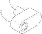
FIG. 3 is a schematic structural view of the power box of the present invention;
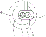
fig. 4 is an enlarged view of the utility model at B in fig. 2.
Description of reference numerals:
1. a support plate; 2. a power box; 3. a drive motor; 4. a driving gear; 5. a support bar; 6. a rotating shaft; 7. a driven gear; 8. a drive wheel; 9. a guide wheel; 10. a material barrel; 11. a stirring motor; 12. a stirring shaft; 13. a stirring paddle; 14. a self-priming pump; 15. a baffle; 16. a spray head; 17. a feed hopper; 18. a mounting frame; 19. a rotating electric machine; 20. a cleaning roller; 21. a heating box; 22. an air pump; 23. heating a tube; 24. a breather plate; 25. a storage battery; 26. a baffle plate; 27. a handrail.
Detailed Description
The technical solutions in the embodiments of the present invention will be clearly and completely described below with reference to the drawings in the embodiments of the present invention, and it is obvious that the described embodiments are only a part of the embodiments of the present invention, and not all of the embodiments. All other embodiments, which can be derived by a person skilled in the art from the embodiments given herein without making any creative effort, shall fall within the protection scope of the present invention.
In order to ensure more uniform spraying of the grindstone terrace, as shown in fig. 1, fig. 2 and fig. 3, a driving mechanism is arranged at the bottom of a supporting plate 1, the driving mechanism comprises a power box 2 and a driving motor 3 fixedly connected with the power box 2, the power box 2 is fixedly welded with the supporting plate 1 through a connecting column, an output shaft of the driving motor 3 extends into the power box 2, a driving gear 4 is fixedly welded on the outer wall of the output shaft of the driving motor 3, a rotating shaft 6 is rotatably connected in the power box 2 through a welded bearing, two supporting rods 5 are symmetrically welded and fixed at the bottom of a supporting seat, the rotating shaft 6 is rotatably connected with the two supporting rods 5 through welded bearings, driving wheels 8 are fixed at two ends of the rotating shaft 6 through bolts, a driven gear 7 meshed with the driving gear 4 is installed on the outer wall of the rotating shaft 6, two guide wheels 9 are symmetrically installed at the bottom of the supporting plate 1 through bolts, two handrails 27 are symmetrically welded and fixed on the surface of the supporting plate 1, the two handrails 27 are positioned on one side of the supporting plate 1, and an operator stands on the side surface of the supporting plate 1 and controls the coating structure to move through the handrails 27, so that the operator is prevented from stepping on the floor surface after coating;
there is material bucket 10 on backup pad 1's surface through the bolt fastening, there is agitator motor 11 at material bucket 10's top through the bolt fastening, shaft coupling fixedly connected with (mixing) shaft 12 is passed through to agitator motor 11's output shaft, the outer wall symmetry welded fastening of (mixing) shaft 12 has a plurality of stirring paddles 13, there is self priming pump 14 on backup pad 1's surface through the bolt fastening, self priming pump 14's inlet tube extends to in the material bucket 10, there is guide plate 15 bottom through the bolt fastening of backup pad 1, the cavity has been seted up in the guide plate 15, self priming pump 14's outlet pipe extends to in the guide plate 15, a plurality of screw holes have been seted up to guide plate 15's bottom, and screw hole female connection has shower nozzle 16, the top welded fastening of material bucket 10 has feeder hopper 17.
In order to ensure the quality of spraying, as shown in fig. 1 and 2, a mounting frame 18 is fixed at the bottom of a support plate 1 through bolts, a cleaning roller 20 is rotatably connected between the mounting frames 18 through a rotating shaft, a soft brush is arranged on the outer wall of the cleaning roller 20 so as to effectively clean dust on the ground, a rotating motor 19 is arranged on the outer wall of one side of the mounting frame 18 through bolts, the cleaning roller 20 is fixedly connected with an output shaft of the rotating motor 19 through a coupler, a heating box 21 is fixed on the surface of the support plate 1 through bolts, an air pump 22 is fixed at the top of the heating box 21 through bolts, an air outlet pipe of the air pump 22 extends into the heating box 21, a plurality of heating pipes 23 are fixed in the heating box 21 through bolts, an air vent plate 24 is fixed at the bottom of the support plate 1 through bolts, the air vent plate 24 is communicated with the heating box 21 through an air vent pipe, and a plurality of air vents are arranged at the bottom of the air vent plate 24, heating pipe 23 can blow in the air of heating cabinet 21 to air pump 22 and heat, blow the air after the heating to the surface of the terrace of spraying again, avoid leading to the unable quick sun-drying of coating because of reasons such as weather, the mounting groove has been seted up on the surface of backup pad 1, and install battery 25 in the mounting groove, battery 25 can provide electric power to this application structure and support, battery 25's top is equipped with baffle 26, baffle 26 passes through bolt and 1 fixed connection of backup pad, one side outer wall of backup pad 1 is equipped with the jack that is used for battery 25 to charge.
Working principle, this epoxy grindstone terrace application structure, when using, pour into in material bucket 10 coating through feeder hopper 17, start agitator motor 11, agitator motor 11 drives stirring rake 13 through (mixing) shaft 12 and rotates, stir coating, guarantee the even of coating, after the coating stirring is accomplished, start driving motor 3, driving motor 3 drives driving gear 4 and rotates, driving gear 4 drives axis of rotation 6 and drive wheel 8 through driven gear 7 and rotates, promote the uniform velocity of this coating mechanism through handrail 27 cooperation leading wheel 9 and move, start rotating electrical machines 19 and self priming pump 14 simultaneously, rotating electrical machines 19 drives cleaning roller 20 and rotates, can be in this coating structure removal process, clear up the dust on ground, self priming pump 14 extracts the coating in material bucket 10 simultaneously, and spray coating on ground evenly through guide plate 15 and shower nozzle 16, accomplish the application of terrace, when meetting weather not good, can start heating pipe 23 and air pump 22, heating pipe 23 can blow in the air of heating cabinet 21 to air pump 22 and heat, blows the surface to the terrace of spraying through breather plate 24 with the air after heating again for the drying rate of terrace.
Finally, it should be noted that: although the present invention has been described in detail with reference to the foregoing embodiments, it will be apparent to those skilled in the art that modifications may be made to the embodiments or portions thereof without departing from the spirit and scope of the utility model.
Claims (5)
1. The utility model provides an epoxy grindstone terrace application structure, includes backup pad (1), sets up in the actuating mechanism of backup pad (1) bottom and sets up in material bucket (10) on backup pad (1) surface, its characterized in that: the driving mechanism comprises a power box (2) and a driving motor (3) fixedly connected with the power box (2), an output shaft of the driving motor (3) extends into the power box (2), a driving gear (4) is installed on the outer wall of the output shaft of the driving motor (3), a rotating shaft (6) is rotatably connected into the power box (2) through a bearing, two supporting rods (5) are symmetrically arranged at the bottom of the supporting seat, the rotating shaft (6) is rotatably connected with the two supporting rods (5) through bearings, driving wheels (8) are fixed at two ends of the rotating shaft (6), and a driven gear (7) meshed with the driving gear (4) is installed on the outer wall of the rotating shaft (6);
agitator motor (11) are installed at the top of material bucket (10), the output shaft of agitator motor (11) passes through shaft coupling fixedly connected with (mixing) shaft (12), a plurality of stirring rakes (13) are installed to the outer wall symmetry of (mixing) shaft (12), the surface mounting of backup pad (1) has self priming pump (14), the inlet tube of self priming pump (14) extends to in material bucket (10), guide plate (15) are installed to the bottom of backup pad (1), the outlet pipe of self priming pump (14) extends to in guide plate (15), a plurality of screw holes have been seted up to the bottom of guide plate (15), and threaded hole female connection has shower nozzle (16), feeder hopper (17) are installed at the top of material bucket (10).
2. The epoxy millstone floor coating structure of claim 1, characterized in that: mounting bracket (18) are installed to the bottom of backup pad (1), it is connected with scrub roller (20) to rotate between mounting bracket (18), rotating electrical machines (19) are installed to one side outer wall of mounting bracket (18), output shaft fixed connection of shaft coupling and rotating electrical machines (19) is passed through in scrub roller (20).
3. The epoxy millstone floor coating structure of claim 1, characterized in that: the surface mounting of backup pad (1) has heating cabinet (21), air pump (22) are installed at the top of heating cabinet (21), the outlet duct of air pump (22) extends to in heating cabinet (21), install a plurality of heating pipes (23) in heating cabinet (21), aeration plate (24) are installed to the bottom of backup pad (1), aeration plate (24) are linked together through breather pipe and heating cabinet (21), a plurality of air vents have been seted up to the bottom of aeration plate (24).
4. The epoxy millstone floor coating structure of claim 3, characterized in that: the mounting groove has been seted up on the surface of backup pad (1), and installs battery (25) in the mounting groove, the top of battery (25) is equipped with baffle (26), one side outer wall of backup pad (1) is equipped with the jack that is used for battery (25) to charge.
5. The epoxy millstone floor coating structure of claim 4, characterized in that: two guide wheels (9) are symmetrically installed at the bottom of the supporting plate (1), and two handrails (27) are symmetrically installed on the surface of the supporting plate (1).
Priority Applications (1)
| Application Number | Priority Date | Filing Date | Title |
|---|---|---|---|
| CN202122201871.8U CN215631395U (en) | 2021-09-11 | 2021-09-11 | Epoxy grindstone terrace application structure |
Applications Claiming Priority (1)
| Application Number | Priority Date | Filing Date | Title |
|---|---|---|---|
| CN202122201871.8U CN215631395U (en) | 2021-09-11 | 2021-09-11 | Epoxy grindstone terrace application structure |
Publications (1)
| Publication Number | Publication Date |
|---|---|
| CN215631395U true CN215631395U (en) | 2022-01-25 |
Family
ID=79915079
Family Applications (1)
| Application Number | Title | Priority Date | Filing Date |
|---|---|---|---|
| CN202122201871.8U Active CN215631395U (en) | 2021-09-11 | 2021-09-11 | Epoxy grindstone terrace application structure |
Country Status (1)
| Country | Link |
|---|---|
| CN (1) | CN215631395U (en) |
Cited By (1)
| Publication number | Priority date | Publication date | Assignee | Title |
|---|---|---|---|---|
| CN114871054A (en) * | 2022-04-26 | 2022-08-09 | 白雪冬 | A kind of automobile body antirust primer coating equipment |
-
2021
- 2021-09-11 CN CN202122201871.8U patent/CN215631395U/en active Active
Cited By (1)
| Publication number | Priority date | Publication date | Assignee | Title |
|---|---|---|---|---|
| CN114871054A (en) * | 2022-04-26 | 2022-08-09 | 白雪冬 | A kind of automobile body antirust primer coating equipment |
Similar Documents
| Publication | Publication Date | Title |
|---|---|---|
| CN207841740U (en) | A kind of mortar mixer with cleaning function | |
| CN110871180A (en) | Cleaning device for construction machinery | |
| CN215878314U (en) | Spray type sand washer | |
| CN211415711U (en) | a forced mixer | |
| CN210880247U (en) | Self-cleaning concrete stirring kettle | |
| CN217840768U (en) | Various sand terrace application structure of epoxy | |
| CN217662985U (en) | Integrated high-speed stirring vacuum emulsifying machine device | |
| CN110420443A (en) | A kind of tennis cleaning device | |
| CN215783888U (en) | Powder coating material crushing device easy to clean | |
| CN213260430U (en) | Colour mixture mixer | |
| CN212167637U (en) | Vertical sand mill is used in coating production | |
| CN220725671U (en) | Flush coater with prevent stifled structure | |
| CN222681298U (en) | Mixing device for building construction | |
| CN215033351U (en) | Sand mixer convenient to clean | |
| CN218307639U (en) | Stirring device for paint sprayer | |
| CN221906591U (en) | A dispersing machine for floor paint production | |
| CN222295581U (en) | Wall material spraying device | |
| CN215319630U (en) | Cement mortar mixing equipment | |
| CN216225682U (en) | Cleaning equipment for lithographic printing ink production device | |
| CN224113733U (en) | Real mineral varnish preparation equipment with self-cleaning function | |
| CN221399728U (en) | Environment-friendly terrace hardener construction device | |
| CN219752010U (en) | Evaporation concentrate deep processing device for photovoltaic power generation | |
| CN220425203U (en) | Stirrer cleaning device | |
| CN221564282U (en) | Gypsum powder storage bin | |
| CN219333893U (en) | Material liquid agitator tank |
Legal Events
| Date | Code | Title | Description |
|---|---|---|---|
| GR01 | Patent grant | ||
| GR01 | Patent grant |