CN215626262U - Crane girder is with upset frock - Google Patents
Crane girder is with upset frock Download PDFInfo
- Publication number
- CN215626262U CN215626262U CN202122278836.6U CN202122278836U CN215626262U CN 215626262 U CN215626262 U CN 215626262U CN 202122278836 U CN202122278836 U CN 202122278836U CN 215626262 U CN215626262 U CN 215626262U
- Authority
- CN
- China
- Prior art keywords
- turnover
- turning
- side plate
- fixedly connected
- hanging
- Prior art date
- Legal status (The legal status is an assumption and is not a legal conclusion. Google has not performed a legal analysis and makes no representation as to the accuracy of the status listed.)
- Active
Links
- 230000007246 mechanism Effects 0.000 claims abstract description 21
- 230000007306 turnover Effects 0.000 claims description 50
- 229910000831 Steel Inorganic materials 0.000 claims description 5
- 239000010959 steel Substances 0.000 claims description 5
- 238000000034 method Methods 0.000 abstract description 9
- 230000008569 process Effects 0.000 description 5
- 230000001360 synchronised effect Effects 0.000 description 4
- 238000010586 diagram Methods 0.000 description 3
- 238000004519 manufacturing process Methods 0.000 description 3
- 230000000694 effects Effects 0.000 description 2
- 230000006978 adaptation Effects 0.000 description 1
- 230000009286 beneficial effect Effects 0.000 description 1
- 230000005611 electricity Effects 0.000 description 1
- 238000001125 extrusion Methods 0.000 description 1
- 238000003754 machining Methods 0.000 description 1
- 230000004048 modification Effects 0.000 description 1
- 238000012986 modification Methods 0.000 description 1
Images



Landscapes
- Conveying And Assembling Of Building Elements In Situ (AREA)
Abstract
The utility model relates to a turning tool for a crane girder, which comprises a hanging beam, wherein turning mechanisms are symmetrically arranged at two ends of the bottom of the hanging beam, each turning mechanism comprises a turning frame, a turning motor and a turning wheel, the turning frames are detachably connected to the bottom of the hanging beam and comprise a first side plate and a second side plate which are parallel to each other, a turning shaft is fixedly connected between the first side plate and the second side plate, the turning wheels are sleeved on the turning shafts, the turning wheels are rotatably connected with the turning shafts through bearings, a first disc and a second disc are fixedly connected to two sides of each turning wheel, the turning motor is fixedly connected to the first side plate, a gear is fixedly connected to one end, which penetrates through the first side plate, of an output shaft of each turning motor, gear teeth matched with the gears are arranged on the outer edges of the first discs, the gear is meshed with the gear teeth on the first discs, and a hoisting belt is sleeved on the turning wheels. The utility model solves the problem that the main beam is easy to cause accidents such as side turning and toppling due to uneven stress by adopting the existing overturning method.
Description
Technical Field
The utility model belongs to the technical field of main beam machining, and particularly relates to a turning tool for a crane main beam.
Background
The crane is a multi-action hoisting machine for vertically lifting and horizontally carrying heavy objects in a certain range, and has a wide application range. The main beam is the main large-scale complicated component of hoist, and whether its structural strength satisfies the requirement, whether the structural style is reasonable direct influence hoist's performance. In the process of manufacturing the main beam, the main beam is turned over as one of necessary production processes, a common turning method is to turn over by using a main lifting hook or an auxiliary lifting hook hanging and lifting belt of one crane, at least 2 persons are needed to cooperate in the turning mode, and the main beam is easy to cause accidents of side turning, overturning and the like due to uneven stress in the turning process, so that unnecessary loss is caused, and the life safety of operators is also threatened.
SUMMERY OF THE UTILITY MODEL
The utility model aims to provide a turning tool for a crane main beam, which solves the problem that the main beam is easy to cause accidents such as side turning and toppling due to uneven stress in the existing turning method.
In order to solve the problems, the utility model adopts the technical scheme that:
a turnover tool for a crane main beam comprises a hanging beam, wherein a plurality of hanging points are fixedly connected to the top of the hanging beam, the hanging points are uniformly arranged on the top of the hanging beam, turnover mechanisms are symmetrically arranged at two ends of the bottom of the hanging beam and comprise turnover frames, turnover motors and turnover wheels, the turnover frames are detachably connected to the bottom end of the hanging beam, each turnover frame comprises a first side plate and a second side plate which are parallel to each other, a turnover shaft is fixedly connected between the first side plate and the second side plate, the turnover wheels are sleeved on the turnover shafts, the turnover wheels are rotatably connected with the turnover shafts through bearings, a first circular ring and a second circular ring are respectively fixedly connected to two sides of each turnover wheel, the first circular ring and the second circular ring are coaxially arranged with the turnover wheels, the turnover motors are fixedly connected to the first side plates, output shafts of the turnover motors penetrate through the first side plates, and gears are fixedly connected to one ends of the output shafts of the turnover motors, the outer edge of the first circular ring is provided with gear teeth matched with the gear, the gear teeth on the first circular ring are meshed with the gear, and the overturning wheel is sleeved with a hoisting belt.
Furthermore, the roll-over stand can be dismantled fixed connection and hang the bottom of roof beam through the flange.
Furthermore, the surface of the turnover wheel is provided with rolled patterns.
Furthermore, the bottom of the hanging beam is fixedly connected with a supporting leg.
Further, the quantity of supporting leg is four, and four supporting legs enclose into the rectangle structure, and four supporting legs set up between two tilting mechanism, and the minimum of supporting leg is less than tilting mechanism's minimum.
Furthermore, the turnover motor is electrically connected with a PLC controller through a power line.
Furthermore, the hanging beam is made of profile steel.
By adopting the technical scheme, the utility model has the beneficial effects that:
two ends of a hanging beam are symmetrically provided with two turnover mechanisms, a turnover motor drives a gear to rotate so as to realize rotation of a turnover wheel, a hoisting belt is sleeved on the turnover wheel, a main beam is sleeved on the hoisting belts on the left side and the right side when the turnover mechanism is used, and the main beam is uniformly stressed in the turnover process through synchronous operation of the two turnover mechanisms, so that accidents such as rollover and toppling of the main beam are avoided; the surface knurling of upset wheel is handled, and the roll extrusion decorative pattern on upset wheel surface can play the antiskid effect, through the frictional force between increase hoist and mount area and the upset wheel to hoist and mount area produces the phenomenon of skidding when avoiding the girder upset.
Drawings
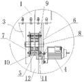
FIG. 1 is a schematic structural diagram of the present invention.
Fig. 2 is a partially enlarged view of a portion a in fig. 1.
FIG. 3 is a schematic diagram illustrating an operating state of the present invention.
FIG. 4 is a second schematic diagram illustrating the working state of the present invention.
Detailed Description
In order to make the objects, technical solutions and advantages of the present invention more clear, embodiments of the present invention are described in further detail below with reference to the accompanying drawings.
As shown in fig. 1 to 4, the utility model provides a turning tool for a crane main beam, which comprises a hanging beam 1, wherein the top of the hanging beam 1 is fixedly connected with a plurality of hanging points 2, the hanging points 2 are uniformly arranged on the top of the hanging beam 1, and the hanging beam 1 is hung in a workshop through a steel wire rope and the like when in use. Hang 1 bottom both ends symmetry of roof beam and be provided with two tilting mechanism, tilting mechanism includes roll-over stand 3, upset motor 4 and trip wheel 5, the bottom of connection at hanging roof beam 1 can be dismantled to roll-over stand 3, roll-over stand 3 includes first curb plate 6 and the second curb plate 7 that are parallel to each other, fixedly connected with trip shaft 8 between first curb plate 6 and the second curb plate 7, 5 covers of trip wheel are established on trip shaft 8, roll-over wheel 5 passes through the bearing rotation with trip shaft 8 and is connected, first ring 9 of bolt fixedly connected with and second ring 10 are passed through respectively in the both sides of trip wheel 5, first ring 9 and second ring 10 all set up with the same axle of trip wheel 5, the external diameter of first ring 9 and the external diameter of second ring 10 all are greater than the diameter of trip wheel 5. Upset motor 4 passes through bolt fixed connection on first curb plate 6, the output shaft of upset motor 4 passes one end fixedly connected with gear 11 of first curb plate 6, be provided with the teeth of a cogwheel with 11 looks adaptations of gear in the outer fringe of first ring 9, the teeth of a cogwheel on the first ring 9 meshes with gear 11 mutually, the cover is equipped with hoist and mount area 12 on the overturning wheel 5, first ring 9 and the second ring 10 that 5 both sides of overturning wheel set up can be spacing to hoist and mount area 12, avoid hoist and mount area 12 in gliding in-process from the both sides landing of overturning wheel 5. When the turnover device is used, the main beam 14 is sleeved on the hoisting belts 12 on the left side and the right side, and the main beam 14 is stressed uniformly in the turnover process through synchronous operation of the two turnover mechanisms, so that accidents such as side turnover, dumping and the like of the main beam 14 are avoided. The hoisting belt in the embodiment is a common overturning hoisting belt with an anti-skid and wear-resistant surface in the prior art.
Furthermore, the roll-over stand 3 can be dismantled fixed connection and hang the bottom of roof beam 1 through the flange, is convenient for install and remove.
Furthermore, the surface of the turning wheel 5 is provided with rolled patterns, the rolled patterns arranged on the surface of the turning wheel 5 can play a role in skid resistance, and the phenomenon that the hoisting belt 12 slips when the main beam 14 turns is avoided by increasing the friction force between the hoisting belt 12 and the turning wheel 5.
Furthermore, the bottom of the hanging beam 1 is fixedly connected with a supporting leg 13.
Further, the quantity of supporting leg 13 is four, and four supporting legs 13 enclose into the rectangle structure, and four supporting legs 13 set up between two tilting mechanism, and the minimum of supporting leg 13 is less than tilting mechanism's minimum. When the hanging beam 1 is taken down and placed on the ground, the supporting legs 13 are used for supporting the hanging beam 1, the supporting legs 13 support the hanging beam 1 to a certain height, and a worker can install the turnover mechanism on the hanging beam 1 conveniently.
Further, upset motor 4 is connected with the PLC controller through the power cord electricity, and in this embodiment, the controller adopts AB company's controlLogix5000 PLC controller, thereby realizes girder 14's upset through 4 work of PLC controller manipulation upset motor, can effectively guarantee staff's safety.
Furthermore, the hanging beam 1 is made of section steel, and the hanging beam 1 is made of section steel, so that the hanging beam is simple to manufacture and attractive in appearance.
The use process comprises the following steps: this upset frock generally is used for the upset operation of girder 14 below 20t, during the use firstly overlap respectively on two tilting mechanism's hoist and mount area 12 with the both ends of the girder 14 of waiting to overturn, make two hoist and mount areas 12 symmetry about girder 14 when placing, then start upset motor 4 through the PLC controller, 4 synchronous operation of the upset motor on two tilting mechanism, thereby the output shaft of upset motor 4 rotates and drives gear 11 and rotate, thereby it rotates along trip shaft 8 to drive trip wheel 5 through the meshing of the teeth of a cogwheel on first ring 9 and gear 11, thereby 5 rotations of trip wheel 5 hoist and mount area 12 on the trip wheel 5 slides along trip wheel 5 under the effect of frictional force, and then drive the girder 14 upset certain angle of hoist and mount area 12 lower part, thereby realize the upset of girder 14 under two synchronous operation of upset motor 4 finally.
The foregoing shows and describes the general principles, essential features, and advantages of the utility model. It will be understood by those skilled in the art that the present invention is not limited to the embodiments described above, which are merely illustrative of the principles of the present invention, but that various changes and modifications may be made without departing from the spirit and scope of the utility model, and the utility model is intended to be covered by the appended claims. The scope of the utility model is defined by the appended claims and equivalents.
Claims (7)
1. The utility model provides a hoist is upset frock for girder which characterized in that: the turnover mechanism comprises a hanging beam, wherein a plurality of hanging points are fixedly connected to the top of the hanging beam, the hanging points are uniformly arranged on the top of the hanging beam, two turnover mechanisms are symmetrically arranged at two ends of the bottom of the hanging beam, each turnover mechanism comprises a turnover frame, a turnover motor and a turnover wheel, the turnover frames are detachably connected to the bottom end of the hanging beam, each turnover frame comprises a first side plate and a second side plate which are parallel to each other, a turnover shaft is fixedly connected between the first side plate and the second side plate, the turnover wheels are sleeved on the turnover shafts, the turnover wheels are rotatably connected with the turnover shafts through bearings, a first circular ring and a second circular ring are respectively and fixedly connected to two sides of each turnover wheel, the first circular ring and the second circular ring are coaxially arranged with the turnover wheels, the turnover motors are fixedly connected to the first side plates, an output shaft of each turnover motor penetrates through the first side plate, a gear is fixedly connected to one end, through which penetrates through the first side plate, gear teeth matched with the gear are arranged on the outer edge of the first circular ring, the gear teeth on the first circular ring are meshed with the gear, and the turning wheel is sleeved with a hoisting belt.
2. The overturning tool for the main beam of the crane according to claim 1, wherein: the roll-over stand passes through the flange and can dismantle fixed connection in the bottom of hanging the roof beam.
3. The overturning tool for the main beam of the crane according to claim 1, wherein: the surface of the turnover wheel is provided with rolled patterns.
4. The overturning tool for the main beam of the crane according to claim 1, wherein: the bottom of the hanging beam is fixedly connected with a supporting leg.
5. The overturning tool for the main beam of the crane according to claim 4, wherein: the quantity of supporting leg is four, and four supporting legs enclose into the rectangle structure, and four supporting legs set up between two tilting mechanism, and the minimum of supporting leg is less than tilting mechanism's minimum.
6. The overturning tool for the main beam of the crane according to claim 1, wherein: the overturning motor is electrically connected with a PLC controller through a power line.
7. The overturning tool for the main beam of the crane according to claim 1, wherein: the hanging beam is made of section steel.
Priority Applications (1)
| Application Number | Priority Date | Filing Date | Title |
|---|---|---|---|
| CN202122278836.6U CN215626262U (en) | 2021-09-18 | 2021-09-18 | Crane girder is with upset frock |
Applications Claiming Priority (1)
| Application Number | Priority Date | Filing Date | Title |
|---|---|---|---|
| CN202122278836.6U CN215626262U (en) | 2021-09-18 | 2021-09-18 | Crane girder is with upset frock |
Publications (1)
| Publication Number | Publication Date |
|---|---|
| CN215626262U true CN215626262U (en) | 2022-01-25 |
Family
ID=79917968
Family Applications (1)
| Application Number | Title | Priority Date | Filing Date |
|---|---|---|---|
| CN202122278836.6U Active CN215626262U (en) | 2021-09-18 | 2021-09-18 | Crane girder is with upset frock |
Country Status (1)
| Country | Link |
|---|---|
| CN (1) | CN215626262U (en) |
-
2021
- 2021-09-18 CN CN202122278836.6U patent/CN215626262U/en active Active
Similar Documents
| Publication | Publication Date | Title |
|---|---|---|
| CN213569280U (en) | Hoisting accessory is used in thermal power plant's maintenance | |
| CN205527406U (en) | Hoist device for building portable | |
| CN206172838U (en) | Change centrifugation and retrieve jack -up suspension arm device of machine | |
| CN217316733U (en) | A flipping hanger for a wind turbine frame | |
| CN211813029U (en) | Grabbing device of crane | |
| CN216945812U (en) | Prevent door type hoisting equipment that scatters and bear device with hoist and mount | |
| CN215711243U (en) | Miniature crane for track | |
| CN115477226A (en) | Hoisting system and method for mechanical automation equipment | |
| CN214734111U (en) | Liftable mobile platform for building construction | |
| CN110834964A (en) | Device is emptyd in former storage bucket transport | |
| CN206666049U (en) | Distribution line cement pole lift | |
| CN213771103U (en) | Hoisting device for hoisting vehicle | |
| CN214031608U (en) | Electric power installation and maintenance platform | |
| CN213141261U (en) | Kiln car overhauls machine of lifting | |
| CN213294457U (en) | Hoisting device is handled to auto-parts surface electrophoresis lacquer | |
| CN215048297U (en) | High-stability hoisting device convenient to move | |
| CN108584752A (en) | Improve the motor vehicle repair crane of working efficiency | |
| CN202011709U (en) | Installation work platform for wind turbine generator set | |
| CN201685477U (en) | Disassembling device for longitudinal beam pressing mold of large linked oil press | |
| CN208200206U (en) | A kind of boom hoisting used in culvert pipe | |
| CN217398271U (en) | Hoisting crane | |
| CN207177390U (en) | A kind of lifting garage | |
| CN214692969U (en) | Safe high-efficient rotatable gallows that is used for steel sheet to lift by crane | |
| CN216971764U (en) | Double-beam bridge crane convenient to maintain | |
| CN210683031U (en) | Portable auxiliary lifting device for paper machine |
Legal Events
| Date | Code | Title | Description |
|---|---|---|---|
| GR01 | Patent grant | ||
| GR01 | Patent grant |