CN215623546U - Electrical containing cabinet convenient to move - Google Patents
Electrical containing cabinet convenient to move Download PDFInfo
- Publication number
- CN215623546U CN215623546U CN202121916053.XU CN202121916053U CN215623546U CN 215623546 U CN215623546 U CN 215623546U CN 202121916053 U CN202121916053 U CN 202121916053U CN 215623546 U CN215623546 U CN 215623546U
- Authority
- CN
- China
- Prior art keywords
- plate
- bevel gear
- cabinet body
- cabinet
- wall
- Prior art date
- Legal status (The legal status is an assumption and is not a legal conclusion. Google has not performed a legal analysis and makes no representation as to the accuracy of the status listed.)
- Expired - Fee Related
Links
- 238000005192 partition Methods 0.000 claims description 26
- 230000005540 biological transmission Effects 0.000 claims description 3
- 230000004308 accommodation Effects 0.000 claims 2
- 241001075561 Fioria Species 0.000 claims 1
- 230000000694 effects Effects 0.000 description 3
- 238000007664 blowing Methods 0.000 description 2
- 238000010586 diagram Methods 0.000 description 2
- 230000001105 regulatory effect Effects 0.000 description 2
- 230000009286 beneficial effect Effects 0.000 description 1
- 230000007547 defect Effects 0.000 description 1
Images


Landscapes
- Ventilation (AREA)
Abstract
The utility model belongs to the technical field of electrical cabinets, and particularly relates to an electrical cabinet convenient to move. The universal wheel air exchange device is reasonable in design, rapid air exchange can be achieved through the mutual matching of the components such as the blower fan blades, the exhaust fan blades, the rotating plate, the filter plate and the rotating screw rod, meanwhile, the universal wheel can be stored and unfolded according to needs, the operation is simple, and the use is convenient.
Description
Technical Field
The utility model relates to the technical field of electrical cabinets, in particular to an electrical containing cabinet convenient to move.
Background
In power plants, electrical equipment is usually loaded in a containment cabinet. A plurality of parallel electrical equipment bearing plates are usually arranged in a common accommodating cabinet from bottom to top, and are respectively used for bearing various electrical equipment such as relay equipment, a circuit breaker, a load switch, a contactor, a measuring instrument and the like.
However, when the accommodating cabinet of the existing electrical equipment is used, the internal air replacement efficiency is poor, and the cabinet is not convenient to move, so that an electrical accommodating cabinet convenient to move is provided for solving the problems.
SUMMERY OF THE UTILITY MODEL
The utility model aims to solve the defects of the prior art and provides an electric containing cabinet convenient to move.
In order to achieve the purpose, the utility model adopts the following technical scheme:
an electric containing cabinet convenient to move comprises a cabinet body, wherein a driving motor is fixedly mounted on the inner wall of the top of the cabinet body, the same upper partition plate is fixedly mounted on the inner walls of the two sides of the cabinet body, a rotating pin is rotatably mounted on the upper partition plate, the top end of the rotating pin is fixedly connected with an output shaft of the driving motor, the bottom end of the rotating pin extends to the lower portion of the upper partition plate, a drum fan blade is fixedly sleeved on the bottom end of the rotating pin, a first belt wheel is fixedly sleeved on the outer side of the rotating pin, a rotating shaft is rotatably mounted on the upper partition plate, a second belt wheel is fixedly sleeved on the top end of the rotating shaft, the first belt wheel and the second belt wheel are rotatably connected with the same transmission belt, an eccentric wheel is fixedly sleeved on the outer side of the rotating shaft, the inner walls of the two sides of the cabinet body are fixedly mounted with the same transverse plate, a plurality of rotating plates are rotatably mounted on the transverse plate, the top ends of the plurality of the rotating plates all extend to the transverse plate and are rotatably mounted with the same L-shaped plate, the eccentric wheel is in contact with one side of the L-shaped plate, a driving bevel gear is fixedly sleeved on the outer side of the rotating shaft, an air outlet is formed in one side of the cabinet body, the same strip-shaped plate is fixedly mounted on the inner wall of the top of the air outlet and the inner wall of the bottom of the air outlet, a driven shaft is rotatably mounted on the strip-shaped plate, a fan exhaust blade is fixedly sleeved at one end of the driven shaft, a driven bevel gear is fixedly sleeved at the other end of the driven shaft and extends into the cabinet body, the driving bevel gear is meshed with the driven bevel gear, a driving bevel gear is fixedly sleeved on the outer side of the rotating shaft, the same lower partition plate is fixedly mounted on the inner walls of two sides of the cabinet body, the bottom end of the rotating shaft is rotatably connected with the lower partition plate, a vertical plate is fixedly mounted at the top side of the lower partition plate, a rotating rod is rotatably mounted on the vertical plate, and a driven bevel gear is fixedly sleeved at one end of the rotating rod, the driving helical gear is meshed with the driven helical gear, a strip-shaped groove is formed in the top side of the lower partition plate, a movable plate is slidably mounted in the strip-shaped groove, a baffle is fixedly mounted on the top side of the movable plate, a hollow shaft is rotatably mounted on one side of the baffle, the other end of the rotating rod extends to one side of the vertical plate and is slidably connected with the inner wall of the hollow shaft, a first bevel gear and a second bevel gear are fixedly sleeved on the outer side of the hollow shaft, the bottom end of a rotating lead screw is rotatably mounted on the inner wall of the bottom of the cabinet body, the top end of the rotating lead screw extends to the upper side of the lower partition plate, a driven bevel gear is fixedly sleeved on the top end of the rotating lead screw, the first bevel gear and the second bevel gear are matched with the driven bevel gear, the same lifting plate is slidably mounted on the inner walls of the two sides of the cabinet body, a sleeve is fixedly mounted on the lifting plate, and a sleeve thread is mounted on the outer side of the rotating lead screw, the bottom side fixed mounting of lifter plate has the top of a plurality of risers, and the bottom of a plurality of risers all extends to the below of the cabinet body and fixed mounting has the universal wheel, the level is provided with a plurality of mounting panels on the both sides inner wall of the cabinet body.
Preferably, one end of a spring is fixedly mounted on the inner wall of the other side of the cabinet body, a connecting plate is fixedly mounted at the other end of the spring, and the connecting plate is fixedly connected with the L-shaped plate.
Preferably, the inner walls of the two sides of the cabinet body are both provided with sliding grooves, the two ends of the lifting plate are respectively slidably mounted in the corresponding sliding grooves, the inner wall of the top of the sliding groove and the inner wall of the bottom of the sliding groove are fixedly provided with a same vertical rod, the lifting plate is provided with two sliding holes, and the two sliding holes are respectively slidably mounted on the outer sides of the corresponding vertical rods.
Preferably, the bottom four corners of the cabinet body are fixedly provided with screws, the thread insert is installed on the outer side of each screw, the bottom of the thread insert is fixedly provided with a supporting plate, and the outer side of the thread insert is fixedly provided with an adjusting wheel in a sleeved mode.
Preferably, the air intake has been seted up at the opposite side top of the cabinet body, the draw-in groove has been seted up on the bottom inner wall of air intake, the bottom of mounting bracket is had in the activity joint in the draw-in groove, the top of mounting bracket extends to the top of the cabinet body and is provided with the pull ring, and is provided with the filter plate on the mounting bracket.
Preferably, the same sliding rod is fixedly mounted on the inner walls of the two sides of the strip-shaped groove, a through hole is formed in the moving plate, and the outer side of the sliding rod is connected with the through hole in a sliding mode.
Preferably, an electric push rod is arranged on the top side of the lower partition plate, and one end of the electric push rod is fixedly connected with one side of the baffle plate.
The utility model has the beneficial effects that: in the utility model, air entering the cabinet body can be filtered under the action of a filter plate, a driving motor drives a rotating pin to blow air to a blowing fan blade, an eccentric wheel, a driving bevel gear and a driving bevel gear are driven by a rotating shaft to synchronously rotate under the action of a belt wheel I, a belt wheel II and a transmission belt, a plurality of rotating plates can be driven to reciprocate under the coordination of the eccentric wheel and a spring so as to guide the air blown by the blowing fan blade, the driving bevel gear drives a driven shaft to drive an exhaust fan blade to rotate through a driven bevel gear so as to discharge the air in the cabinet body, the driving bevel gear drives a rotating rod and a hollow shaft to synchronously rotate through the driven bevel gear, the hollow shaft drives the bevel gear I or the bevel gear II to be meshed with the driven bevel gear by pushing or pulling a baffle plate through an electric push rod, so that a sleeve can drive a lifting plate to lift through a rotating screw rod, and then can drive the universal wheel that corresponds through a plurality of risers and contact or accomodate with ground downwards, be convenient for take out the mounting bracket from the draw-in groove through the pull ring to can carry out quick assembly disassembly to the filter plate.
Drawings
Fig. 1 is a schematic structural view of an electrical cabinet according to the present invention;
FIG. 2 is a schematic structural view of a portion A of a portable electrical cabinet according to the present invention;
fig. 3 is a schematic structural diagram of a portion B of an electrical cabinet according to the present invention, which is easy to move;
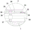
fig. 4 is a schematic structural diagram of a portion C of an electrical cabinet according to the present invention.
In the figure: 1. a cabinet body; 2. a drive motor; 3. an upper partition plate; 4. a rotation pin; 5. a first belt wheel; 6. a blower fan blade; 7. a rotating shaft; 8. a second belt wheel; 9. a drive belt; 10. an eccentric wheel; 11. a transverse plate; 12. a rotating plate; 13. an L-shaped plate; 14. a drive bevel gear; 15. a driven shaft; 16. a driven bevel gear; 17. an exhaust fan blade; 18. a driving bevel gear; 19. rotating the rod; 20. a driven helical gear; 21. a hollow shaft; 22. a strip-shaped groove; 23. moving the plate; 24. a baffle plate; 25. a first bevel gear; 26. a second bevel gear; 27. rotating the screw rod; 28. a driven bevel gear; 29. a lifting plate; 30. a lower baffle plate.
Detailed Description
The technical solutions in the embodiments of the present invention will be clearly and completely described below with reference to the drawings in the embodiments of the present invention, and it is obvious that the described embodiments are only a part of the embodiments of the present invention, and not all of the embodiments.
Referring to fig. 1-4, an electric containing cabinet convenient to move comprises a cabinet body 1, a driving motor 2 is fixedly installed on the inner wall of the top of the cabinet body 1, the same upper partition plate 3 is fixedly installed on the inner walls of two sides of the cabinet body 1, a rotating pin 4 is rotatably installed on the upper partition plate 3, the top end of the rotating pin 4 is fixedly connected with an output shaft of the driving motor 2, the bottom end of the rotating pin 4 extends to the lower side of the upper partition plate 3 and is fixedly sleeved with a blower fan blade 6, a belt wheel 5 is fixedly sleeved on the outer side of the rotating pin 4, a rotating shaft 7 is rotatably installed on the upper partition plate 3, a belt wheel 8 is fixedly sleeved on the top end of the rotating shaft 7, the belt wheel 5 and the belt wheel 8 are rotatably connected with the same driving belt 9, an eccentric wheel 10 is fixedly sleeved on the outer side of the rotating shaft 7, the same transverse plate 11 is fixedly installed on the inner walls of two sides of the cabinet body 1, a plurality of rotating plates 12 are rotatably installed on the transverse plate 11, the top ends of a plurality of rotating plates 12 extend to the upper side of the transverse plate 11 and are rotatably provided with the same L-shaped plate 13, an eccentric wheel 10 is contacted with one side of the L-shaped plate 13, a driving bevel gear 14 is fixedly sleeved on the outer side of the rotating shaft 7, an air outlet is formed in one side of the cabinet body 1, the same strip-shaped plate is fixedly arranged on the inner wall at the top and the inner wall at the bottom of the air outlet, a driven shaft 15 is rotatably arranged on the strip-shaped plate, one end of the driven shaft 15 is fixedly sleeved with an exhaust fan blade 17, the other end of the driven shaft 15 extends into the cabinet body 1 and is fixedly sleeved with a driven bevel gear 16, the driving bevel gear 14 is meshed with the driven bevel gear 16, a driving bevel gear 18 is fixedly sleeved on the outer side of the rotating shaft 7, the same lower partition plate 30 is fixedly arranged on the inner walls at two sides of the cabinet body 1, the bottom end of the rotating shaft 7 is rotatably connected with the lower partition plate 30, a vertical plate is fixedly arranged at the top side of the lower partition plate 30, and a rotating rod 19 is rotatably arranged on the vertical plate, one end of the rotating rod 19 is fixedly sleeved with a driven helical gear 20, the driving helical gear 18 is meshed with the driven helical gear 20, the top side of the lower partition plate 30 is provided with a strip-shaped groove 22, a moving plate 23 is slidably mounted in the strip-shaped groove 22, the top side of the moving plate 23 is fixedly provided with a baffle plate 24, one side of the baffle plate 24 is rotatably provided with a hollow shaft 21, the other end of the rotating rod 19 extends to one side of a vertical plate and is in sliding connection with the inner wall of the hollow shaft 21, the outer side of the hollow shaft 21 is fixedly sleeved with a first bevel gear 25 and a second bevel gear 26, the inner wall of the bottom of the cabinet body 1 is rotatably provided with the bottom end of a rotating lead screw 27, the top end of the rotating lead screw 27 extends to the upper side of the lower partition plate 30 and is fixedly sleeved with a driven bevel gear 28, the first bevel gear 25 and the second bevel gear 26 are matched with the driven bevel gear 28, the inner walls of the two sides of the cabinet body 1 are slidably provided with a same lifting plate 29, and the lifting plate 29 is fixedly provided with a sleeve, and sleeve screw thread installs in the outside of rotating lead screw 27, and the bottom side fixed mounting of lifter plate 29 has the top of a plurality of risers, and the bottom of a plurality of risers all extends to the below of the cabinet body 1 and fixed mounting has the universal wheel, and the level is provided with a plurality of mounting panels on the both sides inner wall of the cabinet body 1.
In this embodiment, fixed mounting has the one end of spring on the opposite side inner wall of the cabinet body 1, and the other end fixed mounting of spring has the connecting plate, and connecting plate and L shaped plate 13 fixed connection, can stimulate L shaped plate 13 through the spring and reset right.
In this embodiment, the spout has all been seted up on the both sides inner wall of the cabinet body 1, and sliding mounting is in the spout that corresponds respectively at the both ends of lifter plate 29, on the top inner wall of spout and on the inner wall of bottom fixed mounting have same montant, has seted up two sliding holes on the lifter plate 29, and two sliding holes are sliding mounting respectively in the outside of the montant that corresponds, can make the motion that lifter plate 29 remain stable through montant and spout.
In this embodiment, the equal fixed mounting in bottom four corners of the cabinet body 1 has the screw rod, and the swivel nut is installed to the outside screw thread of screw rod, and the bottom fixed mounting of swivel nut has the backup pad, and the fixed cover in outside of swivel nut is equipped with the regulating wheel, can carry out the leveling and carry out stable support to the device as required through regulating wheel, swivel nut, screw rod and backup pad.
In this embodiment, the air intake has been seted up at the opposite side top of the cabinet body 1, has seted up the draw-in groove on the bottom inner wall of air intake, and the activity joint has the bottom of mounting bracket in the draw-in groove, and the top of mounting bracket extends to the top of the cabinet body 1 and is provided with the pull ring, and is provided with the filter plate on the mounting bracket, can filter the air that gets into in the cabinet body 1 through the filter plate, can be convenient for change the filter plate and clear up through pull ring, draw-in groove and mounting bracket simultaneously.
In this embodiment, the same slide bar is fixedly mounted on the inner walls of the two sides of the strip-shaped groove 22, the through hole is formed in the moving plate 23, the outer side of the slide bar is slidably connected with the through hole, and the moving plate 23 can stably slide along the strip-shaped groove 22 through the slide bar.
In this embodiment, an electric push rod is disposed on the top side of the lower partition plate 30, one end of the electric push rod is fixedly connected to one side of the baffle plate 24, and the moving plate 23 can be pulled to slide along the strip-shaped groove 22 by the electric push rod.
In the utility model, when in use, firstly, a power supply is switched on, a filter plate is arranged on a mounting frame, the mounting frame is clamped in a clamping groove in an air inlet through a pull ring, a driving motor 2 is started, an output shaft of the driving motor 2 rotates to drive a rotating pin 4 to rotate, the rotating pin 4 blows air through a blower blade 6, a driving belt 9 drives a belt wheel II 8 to rotate through a belt wheel I5 while the rotating pin 4 rotates, the belt wheel II 8 drives an eccentric wheel 10, a driving bevel gear 14 and a driving bevel gear 18 to synchronously rotate through a rotating shaft 7, the eccentric wheel 10 rotates to push an L-shaped plate 13 to move rightwards, a plurality of rotating plates 12 are reciprocated under the coordination of springs, thus guiding the air blown out by the blower blade 6, the driving bevel gear 14 drives a driven shaft 15 to drive an exhaust fan blade 17 to rotate through a driven bevel gear 16, thus exhausting the air in a cabinet body 1, the driving bevel gear 18 drives a rotating rod 19 and a hollow shaft 21 to synchronously rotate through a driven bevel gear 20, promote or stimulate baffle 24 through electric putter and make movable plate 23 slide along the inner wall of strip groove 22, thereby it slides along the outside of dwang 19 to drive hollow shaft 21, along with the removal of hollow shaft 21 position drive bevel gear 25 or bevel gear two 26 and driven bevel gear 28 entering engaged state, thereby can drive rotation lead screw 27 and rotate the sleeve and make lifter plate 29 slide along the spout, can make the motion that lifter plate 29 keeps stable under the effect of montant, thereby it contacts or accomodates with ground downwards to drive the corresponding universal wheel through a plurality of risers, install electrical equipment on the mounting panel can, when needs are changed or are cleared up the filter plate, it can to change or clear up to take out the mounting panel from the draw-in groove through the pull ring.
The above description is only for the preferred embodiment of the present invention, but the scope of the present invention is not limited thereto, and any person skilled in the art should be considered to be within the technical scope of the present invention, and the technical solutions and the utility model concepts of the present invention are equivalent to or changed within the technical scope of the present invention.
Claims (7)
1. The electric containing cabinet convenient to move comprises a cabinet body (1) and is characterized in that a driving motor (2) is fixedly mounted on the inner wall of the top of the cabinet body (1), an upper partition plate (3), a transverse plate (11), a plurality of mounting plates and a lower partition plate (30) are sequentially and fixedly mounted on the inner walls of two sides of the cabinet body (1) from top to bottom, a rotating pin (4) is rotatably mounted on the upper partition plate (3), the top end of the rotating pin (4) is fixedly connected with an output shaft of the driving motor (2), a drum fan blade (6) is fixedly sleeved at the bottom end of the rotating pin (4), a belt wheel I (5) is fixedly sleeved on the outer side of the rotating pin (4), a rotating shaft (7) is rotatably mounted on the upper partition plate (3), a belt wheel II (8) is fixedly sleeved at the top end of the rotating shaft (7), and the belt wheel I (5) and the belt wheel II (8) are rotatably connected with a same transmission belt (9), the fixed cover in the outside of pivot (7) is equipped with eccentric wheel (10), drive bevel gear (14) and initiative helical gear (18), it installs a plurality of rotor plates (12) to rotate on diaphragm (11), and the top of a plurality of rotor plates (12) all extends to the top of diaphragm (11) and rotates and install same L shaped plate (13), eccentric wheel (10) contacts with one side of L shaped plate (13), the air exit has been seted up to one side of the cabinet body (1), and fixed mounting has a bar shaped plate in the air exit, rotate on the bar shaped plate and install driven shaft (15), the fixed cover is equipped with exhaust fan leaf (17) and driven bevel gear (16) respectively at the both ends of driven shaft (15), drive bevel gear (14) meshes with driven bevel gear (16), the bottom of pivot (7) is connected with lower baffle (30) rotation, the top of baffle (30) is rotated and is installed dwang (19) down, the fixed cover of one end of dwang (19) is equipped with driven helical gear (20), initiative helical gear (18) meshes with driven helical gear (20) mutually, bar groove (22) have been seted up to the top side of baffle (30) down, slidable mounting has movable plate (23) in bar groove (22), the top side fixed mounting of movable plate (23) has baffle (24), one side of baffle (24) is rotated and is installed hollow shaft (21), the other end of dwang (19) and the inner wall sliding connection of hollow shaft (21), the outside fixed cover of hollow shaft (21) is equipped with bevel gear (25) and bevel gear two (26), rotate the bottom of installing rotation lead screw (27) on the bottom inner wall of the cabinet body (1), the top of rotation lead screw (27) extends to the top of baffle (30) down and fixed cover is equipped with driven bevel gear (28), the cabinet is characterized in that the first bevel gear (25) and the second bevel gear (26) are matched with the driven bevel gear (28), the inner walls of the two sides of the cabinet body (1) are provided with the same lifting plate (29) in a sliding mode, the lifting plate (29) is fixedly provided with a sleeve, the sleeve is arranged on the outer side of the rotating screw rod (27) in a threaded mode, the bottom side of the lifting plate (29) is fixedly provided with the top ends of a plurality of vertical plates, and the bottom ends of the vertical plates extend to the lower portion of the cabinet body (1) and are fixedly provided with universal wheels.
2. The electric accommodation cabinet convenient to move as claimed in claim 1, wherein one end of the spring is fixedly mounted on the inner wall of the other side of the cabinet body (1), the other end of the spring is fixedly mounted with a connecting plate, and the connecting plate is fixedly connected with the L-shaped plate (13).
3. The electric containing cabinet convenient to move as claimed in claim 1, wherein sliding grooves are formed in the inner walls of the two sides of the cabinet body (1), the two ends of the lifting plate (29) are respectively slidably mounted in the corresponding sliding grooves, the same vertical rod is fixedly mounted on the inner wall of the top of the sliding groove and the inner wall of the bottom of the sliding groove, two sliding holes are formed in the lifting plate (29), and the two sliding holes are respectively slidably mounted on the outer sides of the corresponding vertical rods.
4. The electric containing cabinet convenient to move as claimed in claim 1, wherein four corners of the bottom of the cabinet body (1) are fixedly provided with screws, the outer side of each screw is provided with a threaded sleeve in a threaded manner, the bottom end of each threaded sleeve is fixedly provided with a supporting plate, and the outer side of each threaded sleeve is fixedly provided with an adjusting wheel in a sleeved manner.
5. The electric containing cabinet convenient to move according to claim 1, wherein an air inlet is formed in the top of the other side of the cabinet body (1), a clamping groove is formed in the inner wall of the bottom of the air inlet, the bottom end of the mounting frame is movably clamped in the clamping groove, the top end of the mounting frame extends to the upper side of the cabinet body (1) and is provided with a pull ring, and a filter plate is arranged on the mounting frame.
6. The electric accommodation cabinet convenient to move as claimed in claim 1, wherein the same sliding rod is fixedly mounted on the inner walls of the two sides of the strip-shaped groove (22), the moving plate (23) is provided with a through hole, and the outer side of the sliding rod is slidably connected with the through hole.
7. A portable electrical containment cabinet according to claim 1, wherein the top side of the lower partition (30) is provided with an electrically operated push rod, one end of which is fixedly connected to one side of the baffle (24).
Priority Applications (1)
| Application Number | Priority Date | Filing Date | Title |
|---|---|---|---|
| CN202121916053.XU CN215623546U (en) | 2021-08-16 | 2021-08-16 | Electrical containing cabinet convenient to move |
Applications Claiming Priority (1)
| Application Number | Priority Date | Filing Date | Title |
|---|---|---|---|
| CN202121916053.XU CN215623546U (en) | 2021-08-16 | 2021-08-16 | Electrical containing cabinet convenient to move |
Publications (1)
| Publication Number | Publication Date |
|---|---|
| CN215623546U true CN215623546U (en) | 2022-01-25 |
Family
ID=79898574
Family Applications (1)
| Application Number | Title | Priority Date | Filing Date |
|---|---|---|---|
| CN202121916053.XU Expired - Fee Related CN215623546U (en) | 2021-08-16 | 2021-08-16 | Electrical containing cabinet convenient to move |
Country Status (1)
| Country | Link |
|---|---|
| CN (1) | CN215623546U (en) |
Cited By (2)
| Publication number | Priority date | Publication date | Assignee | Title |
|---|---|---|---|---|
| CN115123984A (en) * | 2022-06-20 | 2022-09-30 | 国网浙江省电力有限公司象山县供电公司 | Cable cover plate lifting device |
| CN119140557A (en) * | 2024-11-21 | 2024-12-17 | 派尔实验装备有限公司 | Renewable self-cleaning type ductless fume hood |
-
2021
- 2021-08-16 CN CN202121916053.XU patent/CN215623546U/en not_active Expired - Fee Related
Cited By (2)
| Publication number | Priority date | Publication date | Assignee | Title |
|---|---|---|---|---|
| CN115123984A (en) * | 2022-06-20 | 2022-09-30 | 国网浙江省电力有限公司象山县供电公司 | Cable cover plate lifting device |
| CN119140557A (en) * | 2024-11-21 | 2024-12-17 | 派尔实验装备有限公司 | Renewable self-cleaning type ductless fume hood |
Similar Documents
| Publication | Publication Date | Title |
|---|---|---|
| CN112736718A (en) | Energy-concerving and environment-protective type electromechanical cubical switchboard | |
| CN218586592U (en) | Spiral lifting structure of conducting rod of grounding switch | |
| CN207625101U (en) | A kind of Novel external formula electrical cabinet | |
| CN114017872B (en) | Energy-conserving ventilation equipment of green building | |
| CN216750941U (en) | Multifunctional power equipment operation maintenance device | |
| CN216872623U (en) | Gymnasium lighting distribution box that radiating effect is good | |
| CN215378108U (en) | Multifunctional power distribution cabinet convenient to remove | |
| CN109119922A (en) | A kind of outdoor distribution box with long service life | |
| CN211859306U (en) | Block terminal with supplementary mounting structure | |
| CN210530993U (en) | Gas turbine air cleaner convenient to dismouting filter core | |
| CN215911280U (en) | Stable and reliable dry-type power transformer | |
| CN209434651U (en) | A kind of power distribution cabinet with electrical mounting base | |
| CN209709530U (en) | A kind of GCK low-tension switch cabinet | |
| CN112168115A (en) | Ceiling fan cleaning device | |
| CN220985158U (en) | Dehumidification mechanism of electric power cabinet | |
| CN218549262U (en) | Movable switch cabinet | |
| CN209217514U (en) | A kind of temporary power case facilitating installation | |
| CN224191487U (en) | Combined nested LCP (liquid crystal display panel) cabinet convenient to disassemble and assemble | |
| CN216631703U (en) | Display screen cleaning device for computer room | |
| CN219868431U (en) | Air exhaust device of air purifier | |
| CN220363651U (en) | Portable zero gas generator device | |
| CN215782241U (en) | Detachable shell for purifier | |
| CN218578463U (en) | Electric power material storage cabinet | |
| CN219976735U (en) | Combined air conditioning unit frame | |
| CN210577126U (en) | Outdoor electrical control cabinet |
Legal Events
| Date | Code | Title | Description |
|---|---|---|---|
| GR01 | Patent grant | ||
| GR01 | Patent grant | ||
| CF01 | Termination of patent right due to non-payment of annual fee |
Granted publication date: 20220125 |
|
| CF01 | Termination of patent right due to non-payment of annual fee |