CN215613486U - Fixed die table cleaning device - Google Patents
Fixed die table cleaning device Download PDFInfo
- Publication number
- CN215613486U CN215613486U CN202122060612.8U CN202122060612U CN215613486U CN 215613486 U CN215613486 U CN 215613486U CN 202122060612 U CN202122060612 U CN 202122060612U CN 215613486 U CN215613486 U CN 215613486U
- Authority
- CN
- China
- Prior art keywords
- fixedly connected
- motor
- sides
- platform
- cleaning device
- Prior art date
- Legal status (The legal status is an assumption and is not a legal conclusion. Google has not performed a legal analysis and makes no representation as to the accuracy of the status listed.)
- Expired - Fee Related
Links
- 238000004140 cleaning Methods 0.000 title claims abstract description 53
- XLYOFNOQVPJJNP-UHFFFAOYSA-N water Substances O XLYOFNOQVPJJNP-UHFFFAOYSA-N 0.000 claims abstract description 55
- 239000002390 adhesive tape Substances 0.000 claims abstract description 12
- 239000007788 liquid Substances 0.000 claims description 21
- 238000007789 sealing Methods 0.000 claims description 12
- 229920001971 elastomer Polymers 0.000 claims description 11
- 238000003860 storage Methods 0.000 claims description 10
- 239000004567 concrete Substances 0.000 abstract description 23
- 239000004568 cement Substances 0.000 abstract description 8
- 239000000463 material Substances 0.000 abstract description 7
- 239000002253 acid Substances 0.000 abstract description 5
- 239000002131 composite material Substances 0.000 abstract description 4
- 239000012459 cleaning agent Substances 0.000 abstract description 3
- 238000005260 corrosion Methods 0.000 abstract description 3
- 230000007797 corrosion Effects 0.000 abstract description 3
- 239000003112 inhibitor Substances 0.000 abstract description 3
- 238000009825 accumulation Methods 0.000 abstract description 2
- 229910052500 inorganic mineral Inorganic materials 0.000 abstract description 2
- JEIPFZHSYJVQDO-UHFFFAOYSA-N iron(III) oxide Inorganic materials O=[Fe]O[Fe]=O JEIPFZHSYJVQDO-UHFFFAOYSA-N 0.000 abstract description 2
- 239000011707 mineral Substances 0.000 abstract description 2
- 239000011435 rock Substances 0.000 abstract description 2
- 231100000241 scar Toxicity 0.000 abstract description 2
- 239000013049 sediment Substances 0.000 abstract description 2
- 230000000694 effects Effects 0.000 description 8
- 238000004519 manufacturing process Methods 0.000 description 6
- 239000002699 waste material Substances 0.000 description 5
- 229920001821 foam rubber Polymers 0.000 description 4
- 238000000034 method Methods 0.000 description 4
- 239000007921 spray Substances 0.000 description 4
- 238000009736 wetting Methods 0.000 description 4
- 229910000831 Steel Inorganic materials 0.000 description 2
- 230000000295 complement effect Effects 0.000 description 2
- 238000013461 design Methods 0.000 description 2
- 238000009434 installation Methods 0.000 description 2
- 238000003475 lamination Methods 0.000 description 2
- 239000000203 mixture Substances 0.000 description 2
- 238000012545 processing Methods 0.000 description 2
- 239000010959 steel Substances 0.000 description 2
- 229920000742 Cotton Polymers 0.000 description 1
- 230000004075 alteration Effects 0.000 description 1
- 230000009286 beneficial effect Effects 0.000 description 1
- 239000003795 chemical substances by application Substances 0.000 description 1
- 150000001875 compounds Chemical class 0.000 description 1
- 238000005516 engineering process Methods 0.000 description 1
- 238000001746 injection moulding Methods 0.000 description 1
- 238000012423 maintenance Methods 0.000 description 1
- 238000012986 modification Methods 0.000 description 1
- 230000004048 modification Effects 0.000 description 1
- 230000003014 reinforcing effect Effects 0.000 description 1
- 239000002689 soil Substances 0.000 description 1
- 239000000243 solution Substances 0.000 description 1
- 238000006467 substitution reaction Methods 0.000 description 1
- 238000010408 sweeping Methods 0.000 description 1
Images



Landscapes
- Cleaning In General (AREA)
Abstract
The utility model discloses a cleaning device for a fixed die table, which comprises a fixed frame, wherein supporting legs are fixedly connected at chamfers at two sides of the lower end of the fixed frame, bearing strips are fixedly connected at two sides inside the fixed frame, a platform is arranged at the upper side of the bottom end of the fixed frame, a driving assembly is arranged at one side of each bearing strip, a vibrator drives the platform to vibrate, under the matching of the vibrating spring and the adhesive tape, the platform can stably rock back and forth, the cleaning of residues is accelerated by matching with the hair net brush, the adhesive tape is convenient for the residual materials to enter the material guide pipe, and because the water tank in the movable seat is added with the cleaning agent for concrete, the composite acid, the corrosion inhibitor, the descaling accelerant and other components, the laminated cement scale, the rust scar and other mineral accumulation can be quickly and thoroughly dissociated, the sediment and the silt in the cement scale can be washed away together, the function of the cleaning component can be better played, and the efficiency of cleaning concrete is high.
Description
Technical Field
The utility model belongs to the field of building processing, and particularly relates to a fixed die table cleaning device.
Background
The fixed mould platform is a steel structure platform with higher flatness, and can also be a cement-based material platform with high flatness and high strength, the fixed mould platform process is mainly designed according to the requirement of production scale, a certain number of fixed mould platforms are arranged in a workshop, and mould assembly, steel bar and embedded part placing, vibrating concrete pouring, member maintenance and demoulding are carried out on the fixed mould platform.
Fixed mould platform production technology, the mould is immovable, operation personnel and reinforcing bar, materials such as concrete flow between each fixed mould platform, concrete PC component can leave the concrete residue on mould platform surface in process of production, the residue can direct influence connect the product quality of follow-up PC component, because most mould platforms do not possess the mechanism of cleaning, clean and all be artifical manual cleaning, inefficiency, waste time and energy, and because the characteristic of muddy earth is few belt cleaning device clean unclean to remaining muddy earth, thereby influence follow-up process velocity.
SUMMERY OF THE UTILITY MODEL
Aiming at the problems in the prior art, the utility model aims to provide a fixed die table cleaning device to solve the problems that the existing die table cleaning device is low in cleaning efficiency, time-consuming and labor-consuming, and the subsequent processing speed is influenced due to the fact that a small part of cleaning devices cannot clean residual concrete due to the characteristics of the concrete.
The technical purpose of the utility model is realized by the following technical scheme:
a fixed die table cleaning device comprises a fixed frame, wherein supporting legs are fixedly connected to chamfers on two sides of the lower end of the fixed frame, bearing strips are fixedly connected to two sides of the interior of the fixed frame, a platform is arranged on the upper side of the bottom end of the fixed frame, a driving assembly is arranged on one side of each bearing strip, a water storage assembly is arranged on one side of each driving assembly, a cleaning assembly is arranged on the inner side of each water storage assembly, a vibration assembly is arranged in the fixed frame, and guide pipes are fixedly connected to two sides of the fixed frame;
the driving assembly comprises a first motor, one side of the first motor is fixedly connected to the left side of the fixing frame, two groups of first motors are arranged, a first lead screw is fixedly connected to the first motor and extends into the bearing strip, the bottom end of the first lead screw is rotatably connected with the bearing strip through a ball bearing, a moving seat is in threaded connection with the outer surface of the first lead screw, the first lead screw is driven to rotate by the first motor through the driving assembly, so that the first lead screw rotates inside the bearing strip, the moving seat is in threaded connection with the outer surface of the first lead screw and is in sliding connection with the inside of the hollow-hole bearing strip, and the moving seat can move back and forth;
the cleaning component comprises a second motor, one side of the second motor is fixedly connected with the upper side of the movable seat, the output end of the second motor passes through the movable seat and is fixedly connected with a second screw rod, the bottom end of the second screw rod is fixedly connected with a hair net brush, the two sides of the lower end of the movable seat are fixedly connected with first guide pipes, the left end and the right end of the movable seat are fixedly connected with second guide pipes, by arranging the cleaning component, after the second motor is electrified, the second motor drives the second screw rod to rotate, thereby driving the brush to clean the platform, removing partial concrete residues, reducing the labor intensity of cleaning of workers, leading out water from the first conduit and the second conduit through the water pump, rapidly wetting the platform, and when the first guide pipe sprays water, the wettability of the hair net brush can be further accelerated through the water guide holes, and the cleaning efficiency of the hair net brush is improved.
Through adopting above-mentioned technical scheme, through setting up drive assembly, the retaining subassembly, clean the subassembly, can leave behind the concrete residue on mould platform surface when concrete PC component in process of production, through driving first motor, first motor drives first lead screw and rotates, thereby make first lead screw rotate in the inside of bearing strip, owing to remove a threaded connection at the surface of first lead screw, and remove a sliding connection in the inside of fretwork bearing strip, thereby make and remove the seat and can the back-and-forth movement, drive the mao net brush and clean the platform after the second motor circular telegram, thereby clear away partial muddy earth residue, reduce staff abluent intensity of labour, ensure the continuity of follow-up injection molding.
Preferably, water guide holes are formed in two sides of the hair net brush, and the water guide holes are inclined.
Through adopting above-mentioned technical scheme, through setting up the water guide hole, can further accelerate the wetness degree of hair net brush through the water guide hole during first pipe water spray, improve the clean efficiency of hair net brush.
The preferred, the retaining subassembly includes the basin, the basin is seted up inside the both sides of removing the seat, the both sides inner wall of removing the seat all is provided with the sealing ring, the inside fixedly connected with connecting pipe of sealing ring, the upper end one side fixedly connected with liquid feeding pipe of removing the seat, sealed lid has been cup jointed to the upper end of liquid feeding pipe.
Through adopting above-mentioned technical scheme, through setting up the retaining subassembly, the basin has been seted up to the inside of removing the seat, one side of basin still is provided with the water pump, the output and the first pipe and the second pipe input of water pump are connected, add muddy earth cleaner through opening the sealed lid on the liquid feeding pipe, it is compound acid to mix the earth cleaner, composition such as anticorrosive agent and scale removal promoter, can dissociate lamination cement dirt fast and thoroughly, connecting pipe cooperation sealing ring makes both sides basin can communicate with each other, play complementary effect.
Preferably, the vibration assembly comprises a placing groove, the placing groove is formed in the left side and the right side of the fixing frame, a vibration spring is fixedly connected to one end of the placing groove, the other end of the vibration spring is fixedly connected with the platform, a mounting groove is formed in the bottom end of the fixing frame, a vibrator is fixedly connected to the inside of the mounting groove, and the output end of the vibrator is fixedly connected with the platform.
Through adopting above-mentioned technical scheme, through setting up the vibration subassembly, set up the mounting groove and be used for installing the vibrator, when needs clean the work to the platform, with the vibrator circular telegram, the vibrating spring drive platform removal reciprocating motion in the vibrator cooperation standing groove for the cooperation coarse cotton net brush that the platform surface can be better cleans, and can go out the vibration of small part muddy earth.
Preferably, both sides of the platform are fixedly connected with adhesive tapes, and one end of each adhesive tape is fixedly connected with the fixing frame.
Through adopting above-mentioned technical scheme, the elastic characteristic of sticky tape can not receive the vibration fracture, plays the effect of connection seal, and the convenience is derived the waste material simultaneously.
Preferably, the bottom ends of the supporting legs are fixedly connected with rubber pads, and tangent planes of the rubber pads are arc-shaped.
Through adopting above-mentioned technical scheme, through setting up the rubber pad, the rubber pad plays the effect of increase friction power for landing leg and ground contact are more stable, reduce the possibility of rocking.
Preferably, the outer portions of the first motor and the second motor are fixedly connected with a case, the inner wall of the case is fixedly connected with a sponge pad, and the sponge pad is tightly attached to the outer surfaces of the first motor and the second motor.
Through adopting above-mentioned technical scheme, through setting up quick-witted case and foam-rubber cushion, play the effect of protection first motor and second motor, avoid first motor and second motor to take place the condition of damaging after using for a long time, and then reduce the shaking force, noise abatement prolongs its life.
Preferably, one side of the upper end of the movable seat is fixedly connected with an alarm, and the alarm is arranged on one side of the liquid adding pipe.
Through adopting above-mentioned technical scheme, through setting up the alarm, after the water level was less than the required water yield when cleaning in the basin, level sensor feeds back to external control ware to make the alarm report to the police, in time inform the staff to add water.
Preferably, the bearing strip is arranged in a semi-hollow shape.
Through adopting above-mentioned technical scheme, through setting up half fretwork shape and bearing the strip, can conveniently remove the seat and slide.
Preferably, the inside of the water tank is fixedly connected with a liquid level sensor.
By adopting the technical scheme, the liquid level sensor is arranged, so that the stock of the liquid is conveniently monitored, and the staff is timely informed to add water.
In summary, the utility model mainly has the following beneficial effects:
firstly, by arranging a driving component, a water storage component and a cleaning component, when concrete residues are left on the surface of a mould table in the production process of a concrete PC component, a first motor is driven to drive a first lead screw to rotate, so that the first lead screw rotates inside a bearing strip;
secondly, through arranging the vibration assembly, the vibrator drives the platform to vibrate, the platform can stably rock back and forth under the matching of the vibration spring and the adhesive tape, the cleaning of residues is accelerated by matching with the hair net brush, the adhesive tape is convenient for the residues to enter the material guide pipe, and because the water tank in the movable seat is added with the cleaning agent for concrete, the composite acid, the corrosion inhibitor, the descaling accelerant and other components, the laminated cement scale, the rust scar and other mineral accumulation can be quickly and thoroughly dissociated, the sediment and the silt in the cement scale can be washed away together, the effect of the cleaning assembly can be better played, and the efficiency of cleaning the concrete is high;
and thirdly, by arranging the liquid level sensor and the alarm, after the water level in the water tank is lower than the water amount required during cleaning, the liquid level sensor feeds back to the external controller, so that the alarm gives an alarm and timely informs a worker of adding water.
Drawings
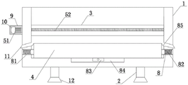
FIG. 1 is a perspective view of the present invention;
FIG. 2 is a schematic structural view of the present invention;
FIG. 3 is a top view of the present invention;
fig. 4 is a side view of the moving seat attachment structure of the present invention.
Reference numerals: 1. a fixed mount; 2. a support leg; 3. a carrier strip; 4. a platform; 5. a drive assembly; 51. a first motor; 52. a first lead screw; 53. a movable seat; 6. a water storage assembly; 61. a water tank; 62. a connecting pipe; 63. a seal ring; 64. a liquid level sensor; 65. a sealing cover; 66. a liquid feeding pipe; 7. a sweeping assembly; 71. a brush for a net; 72. a water guide hole; 73. a first conduit; 74. a second conduit; 75. a second lead screw; 76. a second motor; 8. a vibrating assembly; 81. a placement groove; 82. a vibration spring; 83. a vibrator; 84. mounting grooves; 85. an adhesive tape; 9. a chassis; 10. a sponge cushion; 11. a material guide pipe; 12. a rubber pad; 13. an alarm.
Detailed Description
The technical solutions in the embodiments of the present invention will be clearly and completely described below with reference to the drawings in the embodiments of the present invention, and it is obvious that the described embodiments are only a part of the embodiments of the present invention, and not all of the embodiments. All other embodiments, which can be derived by a person skilled in the art from the embodiments given herein without making any creative effort, shall fall within the protection scope of the present invention.
Example one
Referring to fig. 1 to 4, the fixed mold table cleaning device according to the embodiment includes a fixed frame 1, supporting legs 2 are fixedly connected to chamfers at two sides of the lower end of the fixed frame 1, carrying strips 3 are fixedly connected to two sides of the inside of the fixed frame 1, the carrying strips 3 are arranged in a semi-hollow shape, a platform 4 is arranged on the upper side of the bottom end of the fixed frame 1, a driving assembly 5 is arranged on one side of the carrying strips 3, a water storage assembly 6 is arranged on one side of the driving assembly 5, a cleaning assembly 7 is arranged on the inner side of the water storage assembly 6, a vibrating assembly 8 is arranged inside the fixed frame 1, material guide pipes 11 are fixedly connected to two sides of the fixed frame 1, and a liquid level sensor 64 and an alarm 13 are electrically connected to an external controller;
the driving assembly 5 comprises a first motor 51, one side of the first motor 51 is fixedly connected to the left side of the fixed frame 1, two groups of first motors 51 are arranged, the first motor 51 extends into the bearing strip 3 and is fixedly connected with a first screw 52, the bottom end of the first screw 52 is rotatably connected with the bearing strip 3 through a ball bearing, the outer surface of the first screw 52 is in threaded connection with a moving seat 53, the bearing strip 3 is in a semi-hollow shape, by arranging the driving assembly 5, the first motor 51 drives the first screw 52 to rotate through driving the first motor 51, so that the first screw 52 rotates inside the bearing strip 3, and the moving seat 53 is in threaded connection with the outer surface of the first screw 52 and is in sliding connection with the inside of the semi-hollow bearing strip 3, so that the moving seat 53 can move back and forth;
the cleaning assembly 7 comprises a second motor 76, one side of the second motor 76 is fixedly connected to the upper side of the moving seat 53, the output end of the second motor 76 penetrates through the moving seat 53 and is fixedly connected with a second lead screw 75, the bottom end of the second lead screw 75 is fixedly connected with a brush 71, both sides of the lower end of the moving seat 53 are fixedly connected with first guide pipes 73, both left and right ends of the moving seat 53 are fixedly connected with second guide pipes 74, both sides of the brush 71 are provided with water guide holes 72, the water guide holes 72 are in an oblique shape, by arranging the cleaning assembly 7, after the second motor 76 is electrified, the second motor 76 drives the second lead screw 75 to rotate, so as to drive the brush 71 to clean the platform 4, so as to remove partial soil mixing residues, reduce the labor intensity of cleaning of workers, the first guide pipes 73 and the second guide pipes 74 guide water out through a water pump, so as to quickly wet the platform 4, and when the first conduit 73 sprays water, the wetting degree of the hair net brush 71 can be further accelerated through the water guide holes 72, and the cleaning efficiency of the hair net brush 71 is improved.
Example two
Referring to fig. 1, 2, and 4, in order to facilitate cleaning of the platform 4, in the present embodiment, an innovative design is performed on the water storage assembly 6 on the basis of the first embodiment, specifically, the water storage assembly 6 of the present embodiment includes a water tank 61, the water tank 61 is disposed inside two sides of the movable seat 53, sealing rings 63 are disposed on inner walls of two sides of the movable seat 53, a connecting pipe 62 is fixedly connected inside the sealing rings 63, a liquid feeding pipe 66 is fixedly connected to one side of an upper end of the movable seat 53, and a sealing cover 65 is sleeved on an upper end of the liquid feeding pipe 66; through setting up retaining subassembly 6, basin 61 has been seted up to the inside of removing seat 53, one side of basin 61 still is provided with the water pump, the output and the first pipe 73 and the second pipe 74 input of water pump are connected, add the muddy earth cleaner through opening sealed lid 65 on the filling tube 66, the muddy earth cleaner is composite acid, composition such as resist and scale removal promoter, can dissociate lamination cement dirt fast and thoroughly, connecting pipe 62 cooperation sealing ring 63 makes both sides basin 61 can communicate with each other, play complementary effect.
EXAMPLE III
Referring to fig. 2, in order to accelerate the cleaning efficiency, in the present embodiment, an innovative design is performed on the vibration assembly 8 on the basis of the second embodiment, specifically, the vibration assembly 8 of the present embodiment includes a placement groove 81, the placement groove 81 is disposed on the left and right sides of the fixing frame 1, one end inside the placement groove 81 is fixedly connected with a vibration spring 82, the other end of the vibration spring 82 is fixedly connected with the platform 4, the bottom end of the fixing frame 1 is disposed with an installation groove 84, the inside of the installation groove 84 is fixedly connected with a vibrator 83, an output end of the vibrator 83 is fixedly connected with the platform 4, both sides of the platform 4 are fixedly connected with an adhesive tape 85, and one end of the adhesive tape 85 is fixedly connected with the fixing frame 1; through setting up vibration subassembly 8, set up mounting groove 84, it is used for installing vibrator 83 to set up mounting groove 84, when needs clean the during operation to platform 4, switch on vibrator 83, vibrating spring 82 in vibrator 83 cooperation standing groove 81 drives platform 4 and removes reciprocating motion, make the cooperation coarse fodder brush 71 that platform 4 surface can be better clean, and can go out the vibration of a small part of muddy earth, the elastic characteristic of sticky tape 85 can not receive the vibration fracture, play connection seal's effect, simultaneously, the convenience is derived the waste material.
Example four
Referring to fig. 1 to 4, in order to improve the practicability of the device, in the present embodiment, on the basis of the third embodiment, a rubber pad 12 is fixedly connected to the bottom end of the supporting leg 2, a tangent plane of the rubber pad 12 is set to be arc-shaped, the exterior of the first motor 51 and the second motor 76 are both fixedly connected to the case 9, the inner wall of the case 9 is fixedly connected to a foam-rubber cushion 10, the foam-rubber cushion 10 is tightly attached to the outer surfaces of the first motor 51 and the second motor 76, an alarm 13 is fixedly connected to one side of the upper end of the movable seat 53, the alarm 13 is arranged at one side of the liquid feeding pipe 66, and a liquid level sensor 64 is fixedly connected to the interior of the water tank 61; through setting up rubber pad 12, rubber pad 12 plays the effect of increase friction power, make landing leg 2 more stable with the ground contact, reduce the possibility of rocking, through setting up quick-witted case 9 and foam-rubber cushion 10, play the effect of protection first motor 51 and second motor 76, avoid the condition that takes place to damage after first motor 51 and the long-time use of second motor 76, and then reduce the shaking force, the noise abatement, prolong its life, through setting up alarm 13, after the water level is less than the required water yield when cleaning in basin 61, level sensor 64 feeds back to external control ware, thereby make alarm 13 report to the police, in time inform the staff to add water.
The working principle of the utility model is as follows: when the concrete PC member is used, after concrete residues are left on the surface of a mould table in the production process of the concrete PC member and need to be cleaned, the liquid feeding pipe 66 is added with a cleaning agent for cleaning concrete, a composite acid, a corrosion inhibitor, a descaling accelerant and other components through opening the sealing cover 65, the laminated cement scale can be rapidly and thoroughly dissociated, the effect of the cleaning assembly 7 is better exerted, the efficiency of cleaning the concrete is high, the first motor 51 is driven to drive the first screw rod 52 to rotate, so that the first screw rod 52 rotates in the bearing strip 3, the movable seat 53 is in threaded connection with the outer surface of the first screw rod 52, the movable seat 53 is in sliding connection with the inside of the hollow bearing strip 3, so that the movable seat 53 can move back and forth, after the second motor 76 is electrified, the second motor 76 drives the second screw rod 75 to rotate, so that the rough net brush 71 is driven to clean the platform 4, thereby removing partial concrete residues, reducing the labor intensity of cleaning of workers, leading out water by the first conduit 73 and the second conduit 74 through the water pump, rapidly wetting the platform 4, further accelerating the wetting degree of the mesh brush 71 through the water guide hole 72 when the first conduit 73 sprays water, improving the cleaning efficiency of the mesh brush 71, electrifying the vibrator 83 when the platform 4 needs to be cleaned, leading the vibrator 83 to be matched with the vibrating spring 82 in the placing groove 81 to drive the platform 4 to move and reciprocate, leading the surface of the platform 4 to be better matched with the mesh brush 71 to clean, and vibrating out a small part of concrete, preventing the elastic characteristic of the adhesive tape 85 from being broken by vibration, playing a role of connection sealing, and simultaneously facilitating the leading-out of waste materials, thereby avoiding the condition of time and labor waste of residual manual cleaning, effectively cleaning the concrete on the platform 4, thereby accelerating the subsequent work efficiency of the platform 4.
Although embodiments of the present invention have been shown and described, it will be appreciated by those skilled in the art that changes, modifications, substitutions and alterations can be made in these embodiments without departing from the principles and spirit of the utility model, the scope of which is defined in the appended claims and their equivalents.
Claims (10)
1. The utility model provides a fixed die table cleaning device, includes mount (1), its characterized in that: the supporting legs (2) are fixedly connected to chamfers on two sides of the lower end of the fixing frame (1), bearing strips (3) are fixedly connected to two sides of the interior of the fixing frame (1), the bearing strips (3) are arranged in a semi-hollow shape, a platform (4) is arranged on the upper side of the bottom end of the fixing frame (1), a driving assembly (5) is arranged on one side of each bearing strip (3), a water storage assembly (6) is arranged on one side of each driving assembly (5), a cleaning assembly (7) is arranged on the inner side of each water storage assembly (6), a vibrating assembly (8) is arranged in the fixing frame (1), and guide pipes (11) are fixedly connected to two sides of the fixing frame (1);
the driving assembly (5) comprises first motors (51), one sides of the first motors (51) are fixedly connected to the left side of the fixing frame (1), two groups of first motors (51) are arranged, the first motors (51) extend into the bearing strips (3) and are fixedly connected with first screw rods (52), the bottom ends of the first screw rods (52) are rotatably connected with the bearing strips (3) through ball bearings, and the outer surfaces of the first screw rods (52) are in threaded connection with moving seats (53);
clean subassembly (7) and include second motor (76), one side fixed connection of second motor (76) is at the upside that removes seat (53), the output of second motor (76) passes and removes seat (53) fixedly connected with second lead screw (75), the bottom fixed connection of second lead screw (75) has brush net (71), the equal fixedly connected with first pipe (73) in lower extreme both sides of removing seat (53), remove the equal fixedly connected with second pipe (74) in both ends about seat (53).
2. The fixed die table cleaning device according to claim 1, characterized in that: water guide holes (72) are formed in two sides of the hair net brush (71), and the water guide holes (72) are inclined.
3. The fixed die table cleaning device according to claim 1, characterized in that: retaining subassembly (6) include basin (61), inside basin (61) was seted up in the both sides of removing seat (53), the both sides inner wall of removing seat (53) all is provided with sealing ring (63), inside fixedly connected with connecting pipe (62) of sealing ring (63), upper end one side fixedly connected with liquid feeding pipe (66) of removing seat (53), sealed lid (65) have been cup jointed to the upper end of liquid feeding pipe (66).
4. The fixed die table cleaning device according to claim 1, characterized in that: vibration subassembly (8) include standing groove (81), the left and right sides at mount (1) is seted up in standing groove (81), inside one end fixedly connected with vibrating spring (82) of standing groove (81), the other end and platform (4) fixed connection of vibrating spring (82), mounting groove (84) have been seted up to the bottom of mount (1), the inside fixedly connected with vibrator (83) of mounting groove (84), the output and platform (4) fixed connection of vibrator (83).
5. The fixed die table cleaning device according to claim 4, wherein: the two sides of the platform (4) are fixedly connected with adhesive tapes (85), and one ends of the adhesive tapes (85) are fixedly connected with the fixing frame (1).
6. The fixed die table cleaning device according to claim 1, characterized in that: the bottom end of the supporting leg (2) is fixedly connected with a rubber pad (12), and the tangent plane of the rubber pad (12) is arc-shaped.
7. The fixed die table cleaning device according to claim 1, characterized in that: the motor case is characterized in that the outer portions of the first motor (51) and the second motor (76) are fixedly connected with the machine case (9), the inner wall of the machine case (9) is fixedly connected with a sponge pad (10), and the sponge pad (10) is tightly attached to the outer surfaces of the first motor (51) and the second motor (76).
8. The fixed die table cleaning device according to claim 1, characterized in that: and one side of the upper end of the movable seat (53) is fixedly connected with an alarm (13), and the alarm (13) is arranged on one side of the liquid adding pipe (66).
9. The fixed die table cleaning device according to claim 1, characterized in that: the carrying strip (3) is in a semi-hollow shape.
10. A fixed die table cleaning apparatus according to claim 3, wherein: and a liquid level sensor (64) is fixedly connected inside the water tank (61).
Priority Applications (1)
| Application Number | Priority Date | Filing Date | Title |
|---|---|---|---|
| CN202122060612.8U CN215613486U (en) | 2021-08-30 | 2021-08-30 | Fixed die table cleaning device |
Applications Claiming Priority (1)
| Application Number | Priority Date | Filing Date | Title |
|---|---|---|---|
| CN202122060612.8U CN215613486U (en) | 2021-08-30 | 2021-08-30 | Fixed die table cleaning device |
Publications (1)
| Publication Number | Publication Date |
|---|---|
| CN215613486U true CN215613486U (en) | 2022-01-25 |
Family
ID=79903807
Family Applications (1)
| Application Number | Title | Priority Date | Filing Date |
|---|---|---|---|
| CN202122060612.8U Expired - Fee Related CN215613486U (en) | 2021-08-30 | 2021-08-30 | Fixed die table cleaning device |
Country Status (1)
| Country | Link |
|---|---|
| CN (1) | CN215613486U (en) |
-
2021
- 2021-08-30 CN CN202122060612.8U patent/CN215613486U/en not_active Expired - Fee Related
Similar Documents
| Publication | Publication Date | Title |
|---|---|---|
| CN211618974U (en) | A feed raw material elevator with cleaning equipment | |
| CN219130261U (en) | Cleaning robot applied to photovoltaic panel | |
| CN114472280A (en) | Surface cleaning system for photovoltaic panel and cleaning method thereof | |
| CN117654945A (en) | A cleaning method for single-row swing rod bearings | |
| CN211257842U (en) | Template cleaning equipment for construction | |
| CN218014459U (en) | Aluminum mould board surface cleaning device | |
| CN204769743U (en) | Ultrasonic vibration formula part self - cleaning device is assisted to granule | |
| CN214351586U (en) | Steel bar rust removal equipment for building engineering | |
| CN119926855A (en) | Automatic grinding system for outer mold of box beam model | |
| CN220638408U (en) | A kind of concrete batching machine scraping device | |
| CN219726634U (en) | Concrete vibrating table | |
| CN221499603U (en) | Cleaning device for ribbon conveying crawler belt | |
| CN101428286A (en) | Shaker washer | |
| CN214915502U (en) | Lubricating oil reaction kettle | |
| CN212609461U (en) | A filling equipment for environmentally friendly water-based silicone PU material | |
| CN219258682U (en) | Belt cleaning device of belt conveyor | |
| CN223083453U (en) | Steel pipe surface cleaning device | |
| CN220067356U (en) | Photovoltaic power plant array cleaning equipment | |
| CN223700755U (en) | Apron board maintenance platform | |
| CN216325621U (en) | Bevel gear grinding device with wastewater collection function | |
| CN215702830U (en) | A curing means for concrete processing equipment | |
| CN222613897U (en) | A vibrating device for road and bridge engineering | |
| CN217888827U (en) | Shot blasting machine cleaning device for machining railway fasteners | |
| CN222904402U (en) | A concrete vibrating table | |
| CN223789021U (en) | A cleaning device for anode plates of an electrolytic cell |
Legal Events
| Date | Code | Title | Description |
|---|---|---|---|
| GR01 | Patent grant | ||
| GR01 | Patent grant | ||
| CF01 | Termination of patent right due to non-payment of annual fee | ||
| CF01 | Termination of patent right due to non-payment of annual fee |
Granted publication date: 20220125 |