CN215561957U - Cable-stayed bridge steel tower type vertical rotation installation construction device - Google Patents
Cable-stayed bridge steel tower type vertical rotation installation construction device Download PDFInfo
- Publication number
- CN215561957U CN215561957U CN202121177629.5U CN202121177629U CN215561957U CN 215561957 U CN215561957 U CN 215561957U CN 202121177629 U CN202121177629 U CN 202121177629U CN 215561957 U CN215561957 U CN 215561957U
- Authority
- CN
- China
- Prior art keywords
- wall
- lifting
- fixedly connected
- cable
- tower
- Prior art date
- Legal status (The legal status is an assumption and is not a legal conclusion. Google has not performed a legal analysis and makes no representation as to the accuracy of the status listed.)
- Active
Links
- 229910000831 Steel Inorganic materials 0.000 title claims abstract description 71
- 239000010959 steel Substances 0.000 title claims abstract description 71
- 238000010276 construction Methods 0.000 title claims abstract description 25
- 238000009434 installation Methods 0.000 title claims abstract description 22
- 239000004568 cement Substances 0.000 claims abstract description 15
- 238000000034 method Methods 0.000 description 6
- 238000010586 diagram Methods 0.000 description 3
- 230000007547 defect Effects 0.000 description 2
- 230000001737 promoting effect Effects 0.000 description 2
- 238000004873 anchoring Methods 0.000 description 1
- 230000001174 ascending effect Effects 0.000 description 1
- 230000009286 beneficial effect Effects 0.000 description 1
- 201000010099 disease Diseases 0.000 description 1
- 208000037265 diseases, disorders, signs and symptoms Diseases 0.000 description 1
- 230000000694 effects Effects 0.000 description 1
- 238000012986 modification Methods 0.000 description 1
- 230000004048 modification Effects 0.000 description 1
- 238000003466 welding Methods 0.000 description 1
Images


Landscapes
- Bridges Or Land Bridges (AREA)
Abstract
The utility model discloses a cable-stayed bridge steel tower type vertical rotation installation and construction device which comprises a cement ground, wherein the outer wall of the top of the cement ground is fixedly connected with four lifting towers, the outer wall of one opposite side of each adjacent lifting tower is fixedly connected with connection trusses distributed at equal intervals through bolts, the outer wall of the top of each tower is fixedly connected with two lifting beams through bolts, the outer wall of one opposite side of each lifting beam is fixedly connected with middle transverse plates distributed at equal intervals, the outer wall of one opposite side of each middle transverse plate is welded with a circular tube, and the outer walls of two sides of each lifting beam are welded with lifting lug plates. The utility model can provide upward pulling force for the cross beam ear plate on the outer wall of the top of the original cross beam to lift one end of the steel tower, and the other end of the steel tower can reach the bottom of the lifting tower frame along the sliding track under the action of the lifting oil cylinder, so as to achieve the purpose of erecting the steel tower.
Description
Technical Field
The utility model relates to the technical field of bridge engineering construction, in particular to a cable-stayed bridge steel tower type vertical rotation installation construction device.
Background
With the gradual increase of cable-stayed bridge design in recent years, the steel tower is widely applied by the characteristics of light weight, less later-stage diseases, convenient processing and attractive appearance, the traditional steel tower installation method is a crane hoisting method, and the traditional crane safety process has the advantages of simple and effective construction.
The existing crane safety process has the following defects: the occupation of the crane has higher requirements on site construction sites, foundation bearing capacity conditions and the like, and no crane operation space exists in river-crossing construction or surrounding environment sensitive areas; when the height of the steel tower exceeds 50m, the lifting capacity of a crane is challenged, the height requirement of the crane cannot be met by the conventional crane model, and the scheme has certain limitation; in order to meet the capacity of a crane, the steel tower blocks are often small, so that the field welding work amount is increased, and necessary measures are needed to be taken when the steel tower is welded to cause deformation.
SUMMERY OF THE UTILITY MODEL
The utility model aims to solve the defects in the prior art, and provides a cable-stayed bridge steel tower type vertical rotation installation construction device.
In order to achieve the purpose, the utility model adopts the following technical scheme:
the cable-stayed bridge steel tower type vertical rotation installation and construction device comprises a cement ground, wherein four lifting towers are fixedly connected to the outer wall of the top of the cement ground, the outer wall of one opposite side of each adjacent lifting tower is fixedly connected with connection trusses which are distributed equidistantly through bolts, the outer wall of the top of the tower is fixedly connected with two lifting beams through bolts, the outer wall of one opposite side of each lifting beam is fixedly connected with an intermediate transverse plate which is distributed equidistantly, circular pipes are welded to the outer wall of one opposite side of each intermediate transverse plate, lifting lug plates are welded to the outer walls of two sides of each lifting beam, cable ropes are fixedly connected to the inner walls of the lifting lug plates, a pad beam is fixedly connected to the outer wall of the top of each lifting beam through bolts, three lifting oil cylinders are fixedly connected to the outer wall of the top of the pad beam, the lifting oil cylinders are connected with anchor beams through steel ropes, and two sliding tracks are arranged on the outer wall of the top of the cement ground, and the inner wall of the sliding track is connected with a sliding structure in a sliding way.
Furthermore, the anchor beam comprises an original cross beam, and six cross beam ear plates are fixedly connected to the outer wall of the top of the original cross beam.
Furthermore, variable cross-section sections are arranged at two ends of the original cross beam, and side steel is fixedly connected to the outer wall of one side of each variable cross-section.
Furthermore, the outer wall of the top of the pad beam is provided with a round hole, and the lifting oil cylinder connects the steel rope to the inner wall of the lug plate of the cross beam through the round hole.
Furthermore, one end of the cable wind rope is connected with a bearing platform and an anchor point respectively, and the bearing platform and the anchor point specifically lift the tower for a certain distance.
Furthermore, the two anchor points are located on the same side of the lifting tower and are located on the same straight line with the lifting tower and the bearing platform.
Furthermore, the lifting tower and the sliding track are fixed on the outer wall of the top of the cement ground through concrete bases.
The utility model has the beneficial effects that:
1. this cable-stay bridge steel tower frame formula erects changes installation construction equipment, through being provided with the track that slides, former crossbeam, variable cross section, the side steel, the crossbeam otic placode, the lift cylinder, when installing the steel tower, install the steel tower on the ground earlier, be fixed in the sliding structure on the track that slides with the bottom of steel tower again, pull down the anchor beam, weld the top part of side steel and steel tower through the variable cross section, start the lift cylinder at this moment, when the lift cylinder function, can provide ascending pulling force to the crossbeam otic placode of former crossbeam top outer wall, hoist one end of steel tower, and the other end of steel tower can reach the bottom of lifting tower frame along the track that slides under the effect of lift cylinder, reach the mesh of erectting the steel tower, this kind of method is not restricted by on-site place and environment, therefore, the clothes hanger is strong in practicability.
2. This cable-stay bridge steel tower frame formula erects changes installation construction equipment, through being provided with former crossbeam, variable cross section and side steel, the anchor beam is as steel strand wires anchor structure, and is rotatory along with the steel tower when promoting. The former crossbeam is used to the centre, and the side steel passes through the variable cross section and welds with the steel tower, can be more stable when promoting the steel tower.
3. This cable-stay bridge steel tower formula erects changes installation construction equipment, through being provided with the pipe, the pipe can guarantee the stability between the hoisting beam when the device operation.
The part not related in the device all is the same with prior art or can adopt prior art to realize, and the device design structure is reasonable, and convenient to use satisfies people's user demand.
Drawings
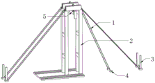
FIG. 1 is an overall three-dimensional structure view of a cable-stayed bridge steel tower type vertical rotation installation construction device provided by the utility model;
FIG. 2 is a three-dimensional structure diagram of a lifting tower of the cable-stayed bridge steel tower type vertical rotation installation construction device provided by the utility model;
FIG. 3 is a three-dimensional structure diagram of an original beam of the cable-stayed bridge steel tower type vertical rotation installation construction device provided by the utility model;
fig. 4 is a three-dimensional structure diagram of a lifting beam of the cable-stayed bridge steel tower type vertical rotation installation construction device provided by the utility model.
In the figure: 1-guy rope, 2-lifting tower, 3-bearing platform, 4-anchor point, 5-original beam, 6-cement ground, 7-sliding track, 8-connection truss, 9-side steel, 10-variable section, 11-beam ear plate, 12-lifting beam, 13-lifting ear plate, 14-middle transverse plate, 15-round tube, 16-pad beam and 17-lifting oil cylinder.
Detailed Description
The technical solution of the present patent will be described in further detail with reference to the following embodiments.
Reference will now be made in detail to embodiments of the present patent, examples of which are illustrated in the accompanying drawings, wherein like or similar reference numerals refer to the same or similar elements or elements having the same or similar function throughout. The embodiments described below with reference to the drawings are exemplary only for the purpose of explaining the present patent and are not to be construed as limiting the present patent.
In the description of this patent, it is to be understood that the terms "center," "upper," "lower," "front," "rear," "left," "right," "vertical," "horizontal," "top," "bottom," "inner," "outer," and the like are used in the orientations and positional relationships indicated in the drawings for the convenience of describing the patent and for the simplicity of description, and are not intended to indicate or imply that the referenced devices or elements must have a particular orientation, be constructed and operated in a particular orientation, and are not to be considered limiting of the patent.
In the description of this patent, it is noted that unless otherwise specifically stated or limited, the terms "mounted," "connected," and "disposed" are to be construed broadly and can include, for example, fixedly connected, disposed, detachably connected, disposed, or integrally connected and disposed. The specific meaning of the above terms in this patent may be understood by those of ordinary skill in the art as appropriate.
Referring to fig. 1-4, a cable-stayed bridge steel tower type vertical rotation installation and construction device comprises a cement ground 6, four lifting towers 2 are fixedly connected to the outer wall of the top of the cement ground 6, connecting trusses 8 which are equidistantly distributed are fixedly connected to the outer wall of one opposite side of each adjacent lifting tower 2 through bolts, two lifting beams 12 are fixedly connected to the outer wall of the top of each tower through bolts, middle transverse plates 14 which are equidistantly distributed are fixedly connected to the outer wall of one opposite side of each of the two lifting beams 12, circular tubes 15 are welded to the outer walls of the opposite sides of the middle transverse plates 14, lifting lug plates 13 are welded to the outer walls of two sides of each lifting beam 12, a cable rope 1 is fixedly connected to the inner walls of the lifting lug plates 13, a backing beam 16 is fixedly connected to the outer wall of the top of each lifting beam 12 through bolts, three lifting oil cylinders 17 are fixedly connected to the outer wall of the top of the backing beam 16, and the lifting oil cylinders 17 are connected to anchor beams through steel cables, the outer wall of the top of the cement ground 6 is provided with two sliding rails 7, and the inner wall of each sliding rail 7 is connected with a sliding structure in a sliding manner.
In the utility model, the anchor beam comprises an original cross beam 5, six cross beam ear plates 11 are fixedly connected to the outer wall of the top of the original cross beam 5, and the cross beam ear plates 11 are used for lifting the original cross beam 5.
In the utility model, variable cross-section sections 10 are arranged at two ends of an original cross beam 5, the outer wall of one side of each variable cross-section 10 is fixedly connected with side steel 9, and the side steel 9 is welded with a steel tower through the variable cross-section sections 10.
According to the utility model, the outer wall of the top of the pad beam 16 is provided with a round hole, the lifting oil cylinder 17 connects the steel rope to the inner wall of the cross beam ear plate 11 through the round hole, and the lifting oil cylinder 17 provides tension for the steel rope.
In the utility model, one end of the cable rope 1 is respectively connected with a bearing platform 3 and an anchor point 4, the bearing platform 3 and the anchor point 4 specifically lift the tower 2 for a certain distance, and the bearing platform 3 and the anchor point 4 are used for ensuring the stability of the lifting tower 2.
In the utility model, the two anchor points 4 are positioned on the same side of the lifting tower 2 and are positioned on the same straight line with the lifting tower 2 and the bearing platform 3.
In the utility model, the lifting tower frame 2 and the sliding track 7 are fixed on the outer wall of the top of the cement ground 6 through concrete bases.
The working principle is as follows: when the steel tower is installed, the steel tower is assembled on the ground, the bottom of the steel tower is fixed to a sliding structure on a sliding rail 7, an anchor beam is pulled down, side steel 9 is welded to the top of the steel tower through a variable cross-section 10, a lifting oil cylinder 17 is started at the moment, when the lifting oil cylinder 17 works, upward pulling force is provided for a cross beam ear plate 11 on the outer wall of the top of an original cross beam 5, one end of the steel tower is lifted, the other end of the steel tower reaches the bottom of a lifting tower frame 2 along the sliding rail 7 under the action of the lifting oil cylinder 17, the purpose of erecting the steel tower is achieved, the method is not limited by site and environment, the anchor beam serves as a steel strand anchoring structure and rotates along with the steel tower during lifting. The middle of the steel tower is welded with the original cross beam 5, the side steel 9 is welded with the steel tower through the variable cross section 10, the steel tower is more stable when being lifted, and the circular tube 15 can ensure the stability between the lifting beams 12 when the device is operated.
The above description is only for the preferred embodiment of the present invention, but the scope of the present invention is not limited thereto, and any person skilled in the art should be considered to be within the technical scope of the present invention, and equivalent alternatives or modifications according to the technical solution of the present invention and the inventive concept thereof should be covered by the scope of the present invention.
Claims (7)
1. The cable-stayed bridge steel tower type vertical rotation installation and construction device comprises cement ground (6) and is characterized in that four lifting towers (2) are fixedly connected to the outer wall of the top of the cement ground (6), connection trusses (8) which are distributed equidistantly are fixedly connected to the outer wall of one opposite side of each adjacent lifting tower (2) through bolts, two lifting beams (12) are fixedly connected to the outer wall of the top of each tower through bolts, middle transverse plates (14) which are distributed equidistantly are fixedly connected to the outer wall of one opposite side of each lifting beam (12), circular tubes (15) are welded to the outer walls of one opposite side of each middle transverse plate (14), lifting lug plates (13) are welded to the outer walls of two sides of each lifting beam (12), a cable rope (1) is fixedly connected to the inner wall of each lifting lug plate (13), and a pad beam (16) is fixedly connected to the outer wall of the top of each lifting beam (12) through bolts, the top outer wall fixedly connected with three promotion hydro-cylinder (17) of pad roof beam (16), promotion hydro-cylinder (17) have the anchor beam through steel cable connection, the top outer wall of cement ground (6) is equipped with two tracks (7) that slide, and the inner wall sliding connection of the track (7) that slides has sliding structure.
2. The cable-stayed bridge steel tower type vertical rotation installation construction device as claimed in claim 1, wherein the anchor beam comprises an original cross beam (5), and the top outer wall of the original cross beam (5) is fixedly connected with six cross beam ear plates (11).
3. The cable-stayed bridge steel tower type vertical rotation installation construction device as claimed in claim 2, wherein the two ends of the original cross beam (5) are respectively provided with a variable cross section (10), and the outer wall of one side of the variable cross section (10) is fixedly connected with side steel (9).
4. The cable-stayed bridge steel tower type vertical rotation installation construction device as claimed in claim 3, wherein a circular hole is formed in the outer wall of the top of the pad beam (16), and the lifting oil cylinder (17) connects a steel rope to the inner wall of the cross beam ear plate (11) through the circular hole.
5. The cable-stayed bridge steel tower type vertical rotation installation construction device as claimed in claim 4, wherein one end of the cable wind rope (1) is connected with a bearing platform (3) and an anchor point (4) respectively, and the bearing platform (3) and the anchor point (4) specifically lift the tower (2) for a certain distance.
6. The cable-stayed bridge steel tower vertical rotation installation construction device as claimed in claim 5, wherein the two anchor points (4) are located on the same side of the lifting tower (2) and are located on the same straight line with the lifting tower (2) and the bearing platform (3).
7. The cable-stayed bridge steel tower vertical rotation installation construction device as claimed in claim 6, wherein the lifting tower (2) and the sliding track (7) are fixed on the outer wall of the top of the cement ground (6) through concrete bases.
Priority Applications (1)
| Application Number | Priority Date | Filing Date | Title |
|---|---|---|---|
| CN202121177629.5U CN215561957U (en) | 2021-05-28 | 2021-05-28 | Cable-stayed bridge steel tower type vertical rotation installation construction device |
Applications Claiming Priority (1)
| Application Number | Priority Date | Filing Date | Title |
|---|---|---|---|
| CN202121177629.5U CN215561957U (en) | 2021-05-28 | 2021-05-28 | Cable-stayed bridge steel tower type vertical rotation installation construction device |
Publications (1)
| Publication Number | Publication Date |
|---|---|
| CN215561957U true CN215561957U (en) | 2022-01-18 |
Family
ID=79864665
Family Applications (1)
| Application Number | Title | Priority Date | Filing Date |
|---|---|---|---|
| CN202121177629.5U Active CN215561957U (en) | 2021-05-28 | 2021-05-28 | Cable-stayed bridge steel tower type vertical rotation installation construction device |
Country Status (1)
| Country | Link |
|---|---|
| CN (1) | CN215561957U (en) |
Cited By (1)
| Publication number | Priority date | Publication date | Assignee | Title |
|---|---|---|---|---|
| CN117266583A (en) * | 2023-10-25 | 2023-12-22 | 中国建筑第四工程局有限公司 | An adaptive vertical rotation lifting system and its construction technology and control method |
-
2021
- 2021-05-28 CN CN202121177629.5U patent/CN215561957U/en active Active
Cited By (1)
| Publication number | Priority date | Publication date | Assignee | Title |
|---|---|---|---|---|
| CN117266583A (en) * | 2023-10-25 | 2023-12-22 | 中国建筑第四工程局有限公司 | An adaptive vertical rotation lifting system and its construction technology and control method |
Similar Documents
| Publication | Publication Date | Title |
|---|---|---|
| CN101514586B (en) | Hanger rail type electric hanging boat and construction method thereof | |
| CN218708558U (en) | Device for hoisting reinforcement cage in cantilever casting segment construction | |
| CN107253675B (en) | A self-propelled tower crown crane | |
| CN109653481A (en) | A kind of hanging rail formula high-altitude operation platform and production method | |
| CN209618736U (en) | Jacking apparatus is climbed in a kind of derrick crane | |
| CN205294665U (en) | Jack -up tower crane based on engineering mechanics | |
| CN103132702A (en) | Longspan pipe truss pulling bar lifting and overhead rotating emplacing construction method | |
| CN110407113A (en) | A kind of construction method of derrick crane installation and displacement | |
| CN110656570A (en) | A telescopic pedestrian bridge, construction device and construction method | |
| CN206692230U (en) | A kind of skyscraper row is hung | |
| CN204625045U (en) | A kind of steel structure hoisting door shaped stent formula hanging apparatus | |
| CN208071235U (en) | A kind of bearing and lifting system of steel truss frame integral hoisting | |
| CN214329956U (en) | Ring rail hoisting device for curtain wall installation | |
| CN201647844U (en) | Beam lifting station without abutments | |
| CN111691419B (en) | Pile driver tower | |
| CN2923644Y (en) | Superhigh super-large high-tonnage walking derricktype lifting machine | |
| CN219060835U (en) | Self-elevating lighting well operation platform device | |
| CN217896261U (en) | Cable crane tower with integrated lifting buckles | |
| CN114855631B (en) | Installation method of multi-beam cable tower | |
| CN217458555U (en) | Manned lifting device of tower crane | |
| CN215925647U (en) | Arch rib buckle cable anchoring beam for tower buckle integration | |
| CN207244453U (en) | A kind of suspension bridge light anchorage mast apparatus | |
| CN212954042U (en) | Lattice formula cable saddle hoist and mount portal | |
| CN215331380U (en) | Rail type suspension platform | |
| CN214114721U (en) | Cantilever crane |
Legal Events
| Date | Code | Title | Description |
|---|---|---|---|
| GR01 | Patent grant | ||
| GR01 | Patent grant |