CN215557308U - Symmetrical feeding device of stacker crane - Google Patents
Symmetrical feeding device of stacker crane Download PDFInfo
- Publication number
- CN215557308U CN215557308U CN202122250390.6U CN202122250390U CN215557308U CN 215557308 U CN215557308 U CN 215557308U CN 202122250390 U CN202122250390 U CN 202122250390U CN 215557308 U CN215557308 U CN 215557308U
- Authority
- CN
- China
- Prior art keywords
- fixed
- fixed mounting
- fixedly arranged
- fixing
- cylinder
- Prior art date
- Legal status (The legal status is an assumption and is not a legal conclusion. Google has not performed a legal analysis and makes no representation as to the accuracy of the status listed.)
- Expired - Fee Related
Links
- 238000009434 installation Methods 0.000 abstract description 9
- 230000000903 blocking effect Effects 0.000 abstract description 5
- 238000012423 maintenance Methods 0.000 abstract description 3
- 239000000463 material Substances 0.000 description 11
- 238000000034 method Methods 0.000 description 2
- 230000002093 peripheral effect Effects 0.000 description 2
- 230000009286 beneficial effect Effects 0.000 description 1
- 238000012986 modification Methods 0.000 description 1
- 230000004048 modification Effects 0.000 description 1
- 239000005022 packaging material Substances 0.000 description 1
Images


Landscapes
- Warehouses Or Storage Devices (AREA)
Abstract
The utility model discloses a symmetrical feeding device of a stacker crane, and relates to the technical field of stacker cranes. The device comprises a left conveying table, a right conveying table, a feeding conveying table and a clamping and fixing device body, wherein a blocking table and a fixing table are fixedly arranged between the left conveying table and the right conveying table, a through groove is formed in the lower surface of the fixing table, an installation table, a fixing disc and an arc-shaped groove are fixedly arranged on the upper surface of the fixing table, a hollow column is rotatably connected to the upper surface of the fixing disc, a hydraulic cylinder is fixedly arranged in the hollow column, a connecting block is fixedly arranged on the upper surface of the hydraulic cylinder, two cross rods are fixedly arranged on two side surfaces of the connecting block, stand columns are fixedly arranged on the lower surfaces of the two cross rods, the lower surfaces of the stand columns and the clamping and fixing device body are fixedly arranged, an air cylinder is fixedly arranged on the upper surface of the installation table, and an ejector rod is fixedly arranged at the output end of the air cylinder. The utility model adopts symmetrical feeding, thereby improving the efficiency in practical use and being convenient for maintenance.
Description
Technical Field
The utility model belongs to the technical field of stacking machines, and particularly relates to a symmetrical feeding device of a stacking machine.
Background
The stacker crane is used for stacking cartons loaded into containers on trays and pallets according to a certain arrangement, automatically stacking the cartons, stacking the cartons into multiple layers, then pushing the cartons out, facilitating the transportation of a forklift to a warehouse for storage, realizing intelligent operation and management by adopting PLC + touch screen control, and being simple and convenient and easy to master. Can greatly reduce labor force and labor intensity. The stacking machine is equipment for automatically stacking bags, cartons or other packaging materials conveyed by a conveyor into stacks according to the working mode of the client process requirements and conveying the stacked materials, and the existing stacking machines are used for one-way loading stacking and have low efficiency in actual use and large consumption of a large amount of material resources, so that the symmetrical loading device of the stacking machine is provided to solve the problems.
SUMMERY OF THE UTILITY MODEL
The utility model aims to provide a symmetrical feeding device of a stacker crane, which solves the problems that the existing stacker cranes are unidirectional in feeding and stacking, the efficiency is low in practical use, and a large amount of material resources are consumed.
In order to solve the technical problems, the utility model is realized by the following technical scheme:
the utility model relates to a symmetrical feeding device of a stacker crane, which comprises a left conveying table, a right conveying table, a feeding conveying table and a clamping and fixing device body, wherein a baffle table and a fixing table are fixedly arranged between the left conveying table and the right conveying table, a through groove is formed in the lower surface of the fixing table, an installation table and a fixing disc are fixedly arranged on the upper surface of the fixing table, an arc-shaped groove is formed in the fixing disc, a hollow column is rotatably connected to the upper surface of the fixing disc, a hydraulic cylinder is fixedly arranged in the hollow column, a connecting block is fixedly arranged on the upper surface of the hydraulic cylinder, two cross rods are fixedly arranged on two side surfaces of the connecting block, a vertical column is fixedly arranged on the lower surfaces of the two cross rods, the lower surfaces of the vertical columns and the clamping and fixing device body are fixedly arranged, an air cylinder is fixedly arranged on the upper surface of the installation table, an ejector rod is fixedly arranged at the output end of the air cylinder, and a rotating shaft is fixedly arranged at one end of the ejector rod, which is far away from the air cylinder, the fixing disc is characterized in that fixing bars are fixedly mounted on the peripheral side faces of the fixing disc, fixing blocks are fixedly mounted on the side faces of the fixing bars, notches are formed in the side faces of the fixing blocks, connecting rods are rotatably connected in the notches, and sliding rods are fixedly mounted on the lower surfaces of the fixing bars.
The feeding conveying table is located between the left conveying table and the right conveying table and fixedly installed with the blocking table.
One end of the connecting rod is rotatably connected with the ejector rod through a rotating shaft, and the other end of the connecting rod is rotatably connected with the fixing block through a notch.
And the two cross rods are fixedly installed through connecting blocks and hydraulic cylinders.
The sliding rod is matched with the arc-shaped groove in size and is in sliding connection with the arc-shaped groove.
The slide bar uses the fixed disk to slide in the arc wall as the central point, through setting up slide bar and arc wall, when the slide bar slides in the arc wall, the fixed block passes through the dead lever and drives the cavity post rotation, can drive pneumatic cylinder and connecting block when the cavity post rotates and rotate to make two horizontal poles direction of rotation.
The cylinder is fixedly installed through the installation table and the fixing table.
The utility model has the following beneficial effects:
according to the utility model, through arranging the air cylinder, the connecting rod and the fixing rod, when the output end of the air cylinder is jacked outwards, the output end of the air cylinder drives the ejector rod to move, the ejector rod drives the connecting rod to rotate through the rotating shaft, the connecting rod rotates in the fixing block through the notch, so that the sliding rod slides in the arc-shaped groove, the fixing block drives the hollow column to rotate through the fixing rod, and the two cross rods rotate in the rotating direction, so that materials are placed on the left conveying table and the right conveying table, therefore, the efficiency is improved in actual use, the consumption of a large number of material resources is reduced, the cost is saved, meanwhile, the structure is simple, the maintenance is convenient, and the maintenance expenditure cost is reduced.
Of course, it is not necessary for any product in which the utility model is practiced to achieve all of the above-described advantages at the same time.
Drawings
In order to more clearly illustrate the technical solutions of the embodiments of the present invention, the drawings used in the description of the embodiments will be briefly introduced below, and it is obvious that the drawings in the following description are only some embodiments of the present invention, and it is obvious for those skilled in the art that other drawings can be obtained according to the drawings without creative efforts.
FIG. 1 is a schematic overall view of a symmetrical loading device of a palletizer according to the present invention;
FIG. 2 is a schematic side view of a symmetrical loading arrangement of a palletiser according to the present invention;
FIG. 3 is a schematic view of a connecting rod of a symmetrical loading device of a palletizer according to the present invention;
FIG. 4 is an enlarged view of a portion A of FIG. 1;
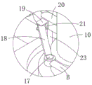
fig. 5 is a partially enlarged view of a portion B of fig. 1.
In the drawings, the components represented by the respective reference numerals are listed below:
1. a left transfer table; 2. a right transfer table; 3. a feeding and conveying table; 4. blocking the platform; 5. a fixed table; 6. a through groove; 7. an installation table; 8. a cylinder; 9. fixing the disc; 10. a hollow column; 11. a hydraulic cylinder; 12. a cross bar; 13. a column; 14. clamping the fixing device body; 15. an arc-shaped slot; 16. a top rod; 17. a rotating shaft; 18. a connecting rod; 19. a fixed block; 20. fixing the rod; 21. a recess; 22. connecting blocks; 23. a slide bar.
Detailed Description
The technical solutions in the embodiments of the present invention will be clearly and completely described below with reference to the drawings in the embodiments of the present invention, and it is obvious that the described embodiments are only a part of the embodiments of the present invention, and not all of the embodiments. All other embodiments, which can be derived by a person skilled in the art from the embodiments given herein without making any creative effort, shall fall within the protection scope of the present invention.
In the description of the present invention, it is to be understood that the terms "upper", "middle", "outer", "inner", and the like, indicate orientations or positional relationships, are used for convenience in describing the present invention and simplifying the description, but do not indicate or imply that the referenced components or elements must have a particular orientation, be constructed and operated in a particular orientation, and thus, should not be construed as limiting the present invention.
Referring to fig. 1-5, the utility model is a symmetrical feeding device of a stacker crane, comprising a left conveying table 1, a right conveying table 2, a feeding conveying table 3 and a clamping and fixing device body 14, wherein a baffle table 4 and a fixed table 5 are fixedly arranged between the left conveying table 1 and the right conveying table 2, a through groove 6 is arranged on the lower surface of the fixed table 5, an installation table 7 and a fixed table 9 are fixedly arranged on the upper surface of the fixed table 5, an arc-shaped groove 15 is arranged on the upper surface of the fixed table 9, a hollow column 10 is rotatably connected with the upper surface of the fixed table 9, a hydraulic cylinder 11 is fixedly arranged in the hollow column 10, a connecting block 22 is fixedly arranged on the upper surface of the hydraulic cylinder 11, two cross rods 12 are fixedly arranged on two side surfaces of the connecting block 22, vertical columns 13 are fixedly arranged on the lower surfaces of the two cross rods 12, a cylinder 8 is fixedly arranged on the lower surface of the vertical column 13 and the clamping and fixing device body 14, an air cylinder 8 is fixedly arranged on the upper surface of the installation table 7, and an ejector rod 16 is fixedly arranged on the output end of the air cylinder 8, one end of the ejector rod 16, which is far away from the air cylinder 8, is fixedly provided with a rotating shaft 17, the peripheral side surface of the fixed disc 9 is fixedly provided with a fixed rod 20, the side surface of the fixed rod 20 is fixedly provided with a fixed block 19, the side surface of the fixed block 19 is provided with a notch 21, the notch 21 is rotatably connected with a connecting rod 18, and the lower surface of the fixed rod 20 is fixedly provided with a sliding rod 23.
The sliding rod 23 is matched with the arc-shaped groove 15 in size, the sliding rod 23 is connected with the arc-shaped groove 15 in a sliding mode, and the sliding rod 23 slides in the arc-shaped groove 15 by taking the fixed disc 9 as a central point.
The feeding conveying table 3 is located between the left conveying table 1 and the right conveying table 2 and fixedly installed with the blocking table 4, and the air cylinder 8 is fixedly installed through the installation table 7 and the fixing table 5.
One end of the connecting rod 18 is rotatably connected with the mandril 16 through a rotating shaft 17, and the other end of the connecting rod 18 is rotatably connected with the fixed block 19 through a notch 21.
Both cross bars 12 are fixedly mounted by means of a connecting block 22 and a hydraulic cylinder 11.
As shown in fig. 1 to 5, this embodiment is a method for using a symmetrical feeding device of a stacker crane: the material is conveyed on the feeding and conveying table 3, the material stacking position is limited by the blocking table 4, when the hydraulic cylinder 11 moves downwards, the hydraulic cylinder 11 drives the two cross rods 12 to move through the connecting block 22, the two cross rods 12 respectively drive the two clamping and fixing device bodies 14 to move and clamp and fix the material on the feeding and conveying table 3, when the hydraulic cylinder 11 jacks upwards, the hydraulic cylinder 11 drives the two cross rods 12 to move through the connecting block 22, when the output end of the air cylinder 8 jacks outwards, the output end of the air cylinder 8 drives the ejector rod 16 to move, the ejector rod 16 drives the connecting rod 18 to rotate through the rotating shaft 17, the connecting rod 18 rotates in the fixed block 19 through the notch 21, so that the sliding rod 23 slides in the arc-shaped groove 15, the fixed block 19 drives the hollow column 10 to rotate through the fixed rod 20, when the hollow column 10 rotates, the hollow column 10 drives the hydraulic cylinder 11 and the connecting block 22 to rotate, so that the two cross rods 12 rotate, and thus the material is placed on the left and right transfer tables 1 and 2.
In the description herein, references to the description of "one embodiment," "an example," "a specific example" or the like are intended to mean that a particular feature, structure, material, or characteristic described in connection with the embodiment or example is included in at least one embodiment or example of the utility model. In this specification, the schematic representations of the terms used above do not necessarily refer to the same embodiment or example. Furthermore, the particular features, structures, materials, or characteristics described may be combined in any suitable manner in any one or more embodiments or examples.
The preferred embodiments of the utility model disclosed above are intended to be illustrative only. The preferred embodiments are not intended to be exhaustive or to limit the utility model to the precise embodiments disclosed. Obviously, many modifications and variations are possible in light of the above teaching. The embodiments were chosen and described in order to best explain the principles of the utility model and the practical application, to thereby enable others skilled in the art to best utilize the utility model. The utility model is limited only by the claims and their full scope and equivalents.
Claims (7)
1. The utility model provides a symmetrical loading attachment of hacking machine, includes left conveying platform (1), right conveying platform (2), pay-off conveying platform (3) and centre gripping fixing device body (14), its characterized in that: fixed mounting has fender platform (4) and fixed station (5) between left side conveying platform (1) and right side conveying platform (2), logical groove (6) have been seted up to fixed station (5) lower surface, fixed station (5) upper surface fixed mounting has mount table (7) and fixed disk (9) to arc wall (15) have been seted up, fixed disk (9) upper surface rotates and is connected with well post (10), well post (10) internal fixed mounting has pneumatic cylinder (11), pneumatic cylinder (11) upper surface fixed mounting has connecting block (22), connecting block (22) both sides face fixed mounting has two horizontal poles (12), two horizontal pole (12) lower surface equal fixed mounting has stand (13), stand (13) lower surface and centre gripping fixing device body (14) fixed mounting, mount table (7) upper surface fixed mounting has cylinder (8), cylinder (8) output end fixed mounting has ejector pin (16), the one end fixed mounting that cylinder (8) were kept away from in ejector pin (16) has axis of rotation (17), fixed disk (9) week side fixed mounting has dead lever (20), dead lever (20) side fixed mounting has fixed block (19), notch (21) have been seted up to fixed block (19) side, notch (21) internal rotation is connected with connecting rod (18), dead lever (20) lower fixed surface installs slide bar (23).
2. A symmetrical feeding device for a palletiser according to claim 1, characterised in that the feeding conveyor (3) is located between the left conveyor (1) and the right conveyor (2) and is fixedly mounted with the stop table (4).
3. A symmetrical loading unit for a palletiser according to claim 1, characterised in that one end of the connecting rod (18) is rotatably connected to the ejector rod (16) by means of a rotating shaft (17), and the other end of the connecting rod (18) is rotatably connected to the fixing block (19) by means of a notch (21).
4. A symmetrical loading device for a palletiser according to claim 1, characterised in that both said cross bars (12) are fixedly mounted by means of a connecting block (22) and a hydraulic cylinder (11).
5. A symmetrical feeding device for a palletiser according to claim 1, characterised in that the sliding bars (23) and the curved slots (15) are of suitable dimensions, the sliding bars (23) being slidingly connected with the curved slots (15).
6. A symmetrical loading device for palletisers according to claim 1, characterised in that the sliding rod (23) slides in an arc-shaped slot (15) with the fixed disk (9) as the centre point.
7. A symmetrical feeding device for a palletiser according to claim 1, characterised in that the cylinder (8) is fixedly mounted by means of a mounting table (7) and a fixed table (5).
Priority Applications (1)
| Application Number | Priority Date | Filing Date | Title |
|---|---|---|---|
| CN202122250390.6U CN215557308U (en) | 2021-09-17 | 2021-09-17 | Symmetrical feeding device of stacker crane |
Applications Claiming Priority (1)
| Application Number | Priority Date | Filing Date | Title |
|---|---|---|---|
| CN202122250390.6U CN215557308U (en) | 2021-09-17 | 2021-09-17 | Symmetrical feeding device of stacker crane |
Publications (1)
| Publication Number | Publication Date |
|---|---|
| CN215557308U true CN215557308U (en) | 2022-01-18 |
Family
ID=79850992
Family Applications (1)
| Application Number | Title | Priority Date | Filing Date |
|---|---|---|---|
| CN202122250390.6U Expired - Fee Related CN215557308U (en) | 2021-09-17 | 2021-09-17 | Symmetrical feeding device of stacker crane |
Country Status (1)
| Country | Link |
|---|---|
| CN (1) | CN215557308U (en) |
-
2021
- 2021-09-17 CN CN202122250390.6U patent/CN215557308U/en not_active Expired - Fee Related
Similar Documents
| Publication | Publication Date | Title |
|---|---|---|
| CN201842289U (en) | Plastic packing tongs for plastic bottles and stacking robot | |
| CN202508627U (en) | Single-column stacker crane | |
| CN203715198U (en) | Forklift device with independently rotated pallet forks | |
| CN220131358U (en) | Rotary carton stacking structure | |
| CN114055439A (en) | Roll-over carrying device of coiled material stacker crane | |
| CN222138092U (en) | Stacker crane clamp | |
| CN107758365A (en) | A kind of feed manufacturing machine stacking machine | |
| CN216763535U (en) | Hydraulic stacking equipment for building material production | |
| CN215797129U (en) | Semi-automatic hacking machine is used to bran processing raw materials | |
| CN115783765A (en) | A intelligent hacking machine for material is carried | |
| CN210682482U (en) | Stacking device | |
| CN2063117U (en) | Clamp for transporting refrigerator | |
| CN202358344U (en) | Rotary ceramic tile packet jacking device | |
| CN208753444U (en) | A kind of cylindrical battery cluster tool | |
| CN215709045U (en) | Telescopic storage goods shelf | |
| CN220998387U (en) | Palletizing robot for edible oil filling production line | |
| CN218658939U (en) | Support frame is used in hacking machine maintenance | |
| CN222041886U (en) | Rotary stack rotating mechanism | |
| CN222743526U (en) | Promote pile up neatly mechanism suitable for carton packagine machine | |
| CN223879026U (en) | A palletizing machine for feed production | |
| CN213140618U (en) | Material supporting and clamping structure of high-order stacker crane | |
| CN221719560U (en) | Automatic warehousing equipment for whole-support products | |
| CN215046872U (en) | Brick pile up neatly device permeates water | |
| CN213265607U (en) | A mobile base for a convenient palletizer | |
| CN222714601U (en) | Pile up neatly portal frame adjustment mechanism |
Legal Events
| Date | Code | Title | Description |
|---|---|---|---|
| GR01 | Patent grant | ||
| GR01 | Patent grant | ||
| CF01 | Termination of patent right due to non-payment of annual fee | ||
| CF01 | Termination of patent right due to non-payment of annual fee |
Granted publication date: 20220118 |