CN215554884U - Prevent corrugated box of horizontal moment power - Google Patents
Prevent corrugated box of horizontal moment power Download PDFInfo
- Publication number
- CN215554884U CN215554884U CN202121885604.0U CN202121885604U CN215554884U CN 215554884 U CN215554884 U CN 215554884U CN 202121885604 U CN202121885604 U CN 202121885604U CN 215554884 U CN215554884 U CN 215554884U
- Authority
- CN
- China
- Prior art keywords
- corrugated
- blocks
- buffer
- fixedly connected
- groove
- Prior art date
- Legal status (The legal status is an assumption and is not a legal conclusion. Google has not performed a legal analysis and makes no representation as to the accuracy of the status listed.)
- Expired - Fee Related
Links
- 230000007246 mechanism Effects 0.000 claims description 11
- 238000009434 installation Methods 0.000 claims description 9
- 244000309464 bull Species 0.000 claims 2
- 238000013016 damping Methods 0.000 claims 2
- 238000001125 extrusion Methods 0.000 abstract description 4
- 230000008859 change Effects 0.000 abstract description 3
- 238000000034 method Methods 0.000 abstract description 3
- 206010040007 Sense of oppression Diseases 0.000 abstract description 2
- 238000006243 chemical reaction Methods 0.000 abstract description 2
- 230000003139 buffering effect Effects 0.000 description 4
- 238000004806 packaging method and process Methods 0.000 description 4
- 230000008901 benefit Effects 0.000 description 2
- 239000011111 cardboard Substances 0.000 description 2
- 238000013461 design Methods 0.000 description 2
- 230000007613 environmental effect Effects 0.000 description 2
- 239000003292 glue Substances 0.000 description 2
- OYPRJOBELJOOCE-UHFFFAOYSA-N Calcium Chemical compound [Ca] OYPRJOBELJOOCE-UHFFFAOYSA-N 0.000 description 1
- 238000004026 adhesive bonding Methods 0.000 description 1
- 230000009286 beneficial effect Effects 0.000 description 1
- 229910052791 calcium Inorganic materials 0.000 description 1
- 239000011575 calcium Substances 0.000 description 1
- 230000006872 improvement Effects 0.000 description 1
- 238000007373 indentation Methods 0.000 description 1
- 230000004048 modification Effects 0.000 description 1
- 238000012986 modification Methods 0.000 description 1
- 238000012856 packing Methods 0.000 description 1
- 239000000123 paper Substances 0.000 description 1
- 239000011087 paperboard Substances 0.000 description 1
- 230000008569 process Effects 0.000 description 1
- 238000012545 processing Methods 0.000 description 1
Images


Landscapes
- Buffer Packaging (AREA)
Abstract
The utility model provides a corrugated case for preventing transverse moment force, which belongs to the technical field of corrugated cases and comprises a corrugated case; multiunit outside buffer gear, when corrugated box suffered from horizontal rectangle and assaulted, can lead to corrugated box to be changed into parallelogram by the rectangle step by step, at this moment when corrugated box conversion in-process, outside buffer gear just can begin work and absorb horizontal rectangle impact force, inboard buffer gear also can set up work simultaneously when it absorbs, then release the impact force and make corrugated box change to the rectangle by parallelogram, thereby make the article in the corrugated box can not receive oppression or extrusion and damage, make user's article obtain complete protection, also make corrugated box keep initial condition simultaneously, improve corrugated box's life.
Description
Technical Field
The utility model belongs to the technical field of corrugated cartons, and particularly relates to a corrugated carton capable of preventing transverse moment.
Background
The corrugated paper board is made into a corrugated paper box through die cutting, indentation, box nailing or box gluing. The corrugated case is a packaging product with the widest application, and the use amount is always the first of various packaging products. Comprises a calcium plastic corrugated case. For more than half a century, corrugated cartons gradually replace transport packaging containers such as wooden boxes and the like with excellent service performance and good processing performance, and become the leading force of transport packaging. It not only protects the goods, is convenient for storage and transportation, but also beautifies the goods and publicizes the goods. The corrugated case belongs to green environmental protection product, and it does benefit to the environmental protection, does benefit to the loading and unloading transportation.
Corrugated box is the most common mode when packing article and transporting, but current corrugated box mostly connects through glue or drawing pin for corrugated box can not cushion oneself when coming from horizontal moment to assault in the face, very easily causes the deformation, and then leads to the goods in the corrugated box to damage, causes user's loss of property.
SUMMERY OF THE UTILITY MODEL
The utility model aims to provide a corrugated case capable of preventing transverse moment force, and aims to solve the problem that in the prior art, most of corrugated cases are connected through glue or drawing pins, and the self-buffering resistance is poor, so that when the corrugated cases are impacted by the transverse moment force, the corrugated cases cannot be relieved by self, further internal goods are damaged, and property loss of users is caused.
In order to achieve the purpose, the utility model provides the following technical scheme:
a corrugated carton for preventing transverse moment forces, comprising:
a corrugated box;
the corrugated carton comprises a plurality of groups of outer side buffer mechanisms, each group of outer side buffer mechanisms consists of an installation block, two first hinged blocks, two first rotating rods, two U-shaped connecting blocks, a first buffer spring and a buffer groove, the installation block is fixedly connected to the lower end of the corrugated carton, the buffer groove is formed in one end of the corrugated carton, the first hinged block positioned on the lower side is fixedly connected to the upper end of the installation block, the first hinged block positioned on the upper side is slidably connected into the buffer groove, the two first rotating rods are respectively and rotatably connected to one ends of the two first hinged blocks, the two U-shaped connecting blocks are respectively and fixedly connected to the circumferential surfaces of the two first rotating rods, and the first buffer spring is fixedly connected to the adjacent ends of the two U-shaped connecting blocks; and
And the multiple groups of inner side buffer mechanisms are connected with the corrugated case to realize secondary buffering of the corrugated case.
As a preferable scheme of the present invention, each of the inner side buffer mechanisms is composed of two second hinge blocks, two second rotating rods, two second buffer springs, a force unloading groove and a plurality of force unloading blocks, the force unloading groove is opened on the lower inner wall of the corrugated case, the second hinge block located on the lower side is slidably connected in the force unloading groove, the second hinge block located on the upper side is fixedly connected to one inner wall of the corrugated case, the two second rotating rods are respectively and rotatably connected to one end of the two second hinge blocks, the plurality of force unloading blocks are respectively and fixedly connected to the circumferential surfaces of the two second rotating rods, and the two second buffer springs are respectively and fixedly connected between the adjacent ends of the plurality of force unloading blocks.
As a preferable scheme of the utility model, the adjacent ends of the two U-shaped connecting blocks and the plurality of force unloading blocks are respectively and fixedly connected with a first spring telescopic rod and a second spring telescopic rod.
As a preferred scheme of the utility model, the inner walls of the two sides of the buffer groove are respectively provided with a first limiting groove, the two ends of the first hinge block positioned at the upper side are respectively fixedly connected with a first limiting block, and the two first limiting blocks are respectively connected in the two first limiting grooves in a sliding manner.
As a preferable scheme of the utility model, the inner walls of both sides of the force unloading groove are respectively provided with a second limiting groove, both ends of the second hinge block positioned at the lower side are respectively fixedly connected with a second limiting block, and the two second limiting blocks are respectively connected in the two second limiting grooves in a sliding manner.
As a preferable scheme of the present invention, four corners of the lower end of the corrugated carton are fixedly connected with placing blocks, and the upper and lower inner walls of the buffer slot are fixedly connected with anti-collision blocks.
Compared with the prior art, the utility model has the beneficial effects that:
1. in this scheme, when corrugated box suffered from horizontal rectangle and assaulted, can lead to corrugated box to be changed into parallelogram by the rectangle step by step, at this moment when corrugated box conversion in-process, outside buffer gear just can begin work and absorb horizontal rectangle impact force, inboard buffer gear also can set up work in step when it is absorptive, then release the impact force and make corrugated box change to the rectangle by parallelogram, thereby make the article in the corrugated box can not receive oppression or extrusion and damage, make user's article obtain complete protection, also make corrugated box keep initial state simultaneously, improve corrugated box's life.
2. In this scheme, receive the impact at first articulated piece and when sliding in the dashpot, can slide at first spacing inslot through making first stopper, restrict the slip of first articulated piece through such mode, in the break away from the dashpot that leads to because the atress is uneven when preventing it from sliding to improve the life of this device.
3. In this scheme, when needs place corrugated box on subaerial, can place corrugated box more stable placing through placing the piece, prevent that it from producing the friction with ground, and then improve corrugated box's life, and when first articulated piece passes through the dashpot and slides, can make first articulated piece obtain certain buffering when touching with the dashpot through the anticollision piece, prevent that this device that the striking leads to between first articulated piece and the dashpot from damaging, and then improve this device's life.
Drawings
The accompanying drawings, which are included to provide a further understanding of the utility model and are incorporated in and constitute a part of this specification, illustrate embodiments of the utility model and together with the description serve to explain the principles of the utility model and not to limit the utility model. In the drawings:
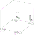
FIG. 1 is a perspective view of the present invention;
FIG. 2 is a main sectional view of the present invention;
fig. 3 is a bottom view of the present invention.
In the figure: 1. a corrugated box; 2. placing the blocks; 3. mounting blocks; 4. a first hinge block; 5. a first rotating lever; 6. a U-shaped connecting block; 7. a first buffer spring; 8. a first spring telescopic rod; 9. a buffer tank; 10. a first stopper; 11. an anti-collision block; 12. a second hinge block; 13. a second limiting block; 14. a second rotating rod; 15. a second buffer spring; 16. the second spring telescopic rod.
Detailed Description
The technical solutions in the embodiments of the present invention will be clearly and completely described below with reference to the drawings in the embodiments of the present invention, and it is obvious that the described embodiments are only a part of the embodiments of the present invention, and not all of the embodiments. All other embodiments, which can be derived by a person skilled in the art from the embodiments given herein without making any creative effort, shall fall within the protection scope of the present invention.
Example 1
Referring to fig. 1-3, the present invention provides the following technical solutions:
a corrugated carton for preventing transverse moment forces, comprising:
a corrugated box 1;
each group of outer side buffer mechanisms consists of an installation block 3, two first hinged blocks 4, two first rotating rods 5, two U-shaped connecting blocks 6, a first buffer spring 7 and a buffer groove 9, wherein the installation block 3 is fixedly connected to the lower end of the corrugated case 1, the buffer groove 9 is formed in one end of the corrugated case 1, the first hinged block 4 on the lower side is fixedly connected to the upper end of the installation block 3, the first hinged block 4 on the upper side is slidably connected into the buffer groove 9, the two first rotating rods 5 are respectively and rotatably connected to one ends of the two first hinged blocks 4, the two U-shaped connecting blocks 6 are respectively and fixedly connected to the circumferential surfaces of the two first rotating rods 5, and the first buffer spring 7 is fixedly connected to the adjacent ends of the two U-shaped connecting blocks 6; and
The multiple groups of inner side buffer mechanisms are connected with the corrugated case 1 to realize secondary buffering.
In the embodiment of the present invention, when the left side of the corrugated container 1 is impacted, which causes the corrugated container 1 to slowly change from a rectangular shape to a parallelogram shape, the first rotating rod 5 on the right side of the corrugated container 1 starts to rotate, the first buffer spring 7 and the first telescopic spring rod 8 are forced to be extended by the rotation of the first rotating rod, the first hinge block 4 on the right side slides down in the buffer slot 9, the first buffer spring 7 and the first telescopic spring rod 8 are extended again while sliding, the impact force is primarily buffered by the contractibility of the first hinge block, the left end of the corrugated container 1 starts to incline and press one of the first hinge blocks 4 to slide upwards in the buffer slot 9 when the corrugated container 1 is impacted, and the first buffer spring 7 and the first telescopic spring rod 8 on the left side of the corrugated container 1 are pressed when the corrugated container is slid, the corrugated carton 1 can store and gradually digest the impact force, when the impact force gradually subsides, the left first buffer spring 7 and the first spring telescopic rod 8 release the stored force to restore the deformed corrugated carton 1 to be rectangular again from the parallelogram, at the moment, the right end of the corrugated carton 1 is upward moved in the buffer groove 9 by the release force from the left first buffer spring 7 on the upper side of the first hinged block 4, so that the right parts return to the initial state, and the rectangular state of the corrugated carton 1 is maintained, the rectangular force from the left end and the right end can be resisted to the greatest extent through the design, the corrugated carton 1 is not deformed in a large scale, articles in the corrugated carton 1 are protected, the property of a user is guaranteed, and the damage cannot be caused.
Specifically referring to fig. 2, each group of inner side buffer mechanisms is composed of two second hinged blocks 12, two second rotating rods 14, two second buffer springs 15, a force unloading groove and a plurality of force unloading blocks, the force unloading groove is formed in the lower inner wall of the corrugated case 1, the second hinged block 12 located on the lower side is slidably connected in the force unloading groove, the second hinged block 12 located on the upper side is fixedly connected to the inner wall of one side of the corrugated case 1, the two second rotating rods 14 are respectively and rotatably connected to one ends of the two second hinged blocks 12, the plurality of force unloading blocks are respectively and fixedly connected to the circumferential surfaces of the two second rotating rods 14, and the two second buffer springs 15 are respectively and fixedly connected between the adjacent ends of the plurality of force unloading blocks.
In this embodiment: when the right-hand member at corrugated box 1 received horizontal impact, at this moment the right-hand member of corrugated box 1 just can receive the extrusion, and extrude second buffer spring 15 and second spring telescopic link 16 and cushion the impact force that comes from the right-hand member through it, when second spring telescopic link 16 cushions the impact force, can also slide in unloading the power groove through articulated piece 12 of second, and then further cushion the impact force, and when the impact force subsided, through second buffer spring 15 and the 16 releasing ability of second spring telescopic link, convert corrugated box 1 into the rectangle again, article through such design can make in the corrugated box 1 obtain further protection, improve user's article protectiveness, prevent its damage.
Referring to fig. 3, first limiting grooves are formed in inner walls of two sides of the buffer groove 9, first limiting blocks 10 are fixedly connected to two ends of the first hinge block 4 located on the upper side, and the two first limiting blocks 10 are slidably connected to the two first limiting grooves respectively.
In this embodiment: receive the extrusion and when the dashpot 9 slides at first articulated piece 4, can slide through two first stopper 10 at two first spacing inslots, can improve the sliding stability of first articulated piece 4 through such slip, prevent to lead to first articulated piece 4 to break away from in the dashpot 9 because the atress is uneven, and then improve the stability in use and the safety in utilization of this device.
Referring to fig. 2, the inner walls of the two sides of the force-releasing groove are respectively provided with a second limiting groove, two ends of the second hinge block 12 located at the lower side are respectively fixedly connected with a second limiting block 13, and the two second limiting blocks 13 are respectively connected in the two second limiting grooves in a sliding manner.
In this embodiment: when the second hinged block 12 is influenced by the impact force and slides in the force unloading groove, the second limiting block 13 can slide in the second limiting groove to limit the sliding of the second hinged block 12, so that the second hinged block cannot be separated from the force unloading groove, and the use safety of the device is further improved.
Specifically referring to fig. 3, the four corners of the lower end of the corrugated case 1 are fixedly connected with the placing blocks 2, and the upper and lower inner walls of the buffer slot 9 are fixedly connected with the anti-collision blocks 11.
In this embodiment: when needs place corrugated box 1 on subaerial, can be through placing the more stable placing of corrugated box 1 of piece 2, prevent that it from producing the friction with ground, and then improve corrugated box 1's life, and when first articulated piece 4 slides through dashpot 9, can make first articulated piece 4 obtain certain buffering when bumping against 9 with dashpot through anticollision piece 11, prevent that this device that the striking leads to between first articulated piece 4 and the dashpot 9 from damaging, and then improve this device's life.
The working principle and the using process of the utility model are as follows: when the left side of the corrugated case 1 is impacted, the corrugated case 1 is slowly transformed from a rectangle into a parallelogram, the first hinge block 4 on the right side slides down in the buffer slot 9, the first buffer spring 7 and the first telescopic spring rod 8 are stretched while sliding, the impact force is firstly buffered through the contractility of the first hinge block 4, the left end of the corrugated case 1 begins to incline and press one of the first hinge blocks 4 when the corrugated case is impacted, the first buffer spring 7 and the first telescopic spring rod 8 on the left side of the corrugated case 1 are pressed and slide upwards in the buffer slot 9, the impact force is accumulated and gradually digested, and when the impact force is gradually subsided, the force accumulated by the first buffer spring 7 and the first telescopic spring rod 8 on the left side is released to restore the deformed corrugated case 1 from the parallelogram into the rectangle again, in this case, the first hinge block 4 at the right end of the corrugated cardboard box 1 on the upper side is moved upward in the buffer groove 9 by the releasing force from the first buffer spring 7 on the left side, and the right-side components are returned to the initial state, and the rectangular state of the corrugated cardboard box 1 is maintained.
Finally, it should be noted that: although the present invention has been described in detail with reference to the foregoing embodiments, it will be apparent to those skilled in the art that changes may be made in the embodiments and/or equivalents thereof without departing from the spirit and scope of the utility model. Any modification, equivalent replacement, or improvement made within the spirit and principle of the present invention should be included in the protection scope of the present invention.
Claims (6)
1. A corrugated box for preventing a transverse moment, comprising:
a corrugated box (1);
a plurality of groups of outer side buffer mechanisms, each group of outer side buffer mechanisms consists of an installation block (3), two first hinging blocks (4), two first rotating rods (5), two U-shaped connecting blocks (6), a first buffer spring (7) and a buffer groove (9), the installation block (3) is fixedly connected to the lower end of the corrugated case (1), the buffer groove (9) is arranged at one end of the corrugated case (1), the first hinged block (4) positioned at the lower side is fixedly connected to the upper end of the installation block (3), the first hinged block (4) positioned at the upper side is slidably connected into the buffer groove (9), the two first rotating rods (5) are respectively and rotatably connected to one end of the two first hinged blocks (4), the two U-shaped connecting blocks (6) are respectively and fixedly connected to the circumferential surfaces of the two first rotating rods (5), the first buffer spring (7) is fixedly connected to the close ends of the two U-shaped connecting blocks (6); and
The multi-group inner side buffer mechanisms are connected with the corrugated case (1) to realize secondary buffer.
2. The corrugated carton for preventing transverse moment according to claim 1, wherein each set of the inner damping mechanisms is composed of two second hinge blocks (12), two second rotating rods (14), two second damping springs (15), a force-releasing groove, and a plurality of force-releasing blocks, unload power groove and open in the lower inner wall of corrugated box (1), be located the downside the articulated piece of second (12) sliding connection is in unloading the power inslot, is located the upside the articulated piece of second (12) fixed connection is in one side inner wall of corrugated box (1), two second bull stick (14) rotate respectively to be connected in the one end of the articulated piece of two seconds (12), and is a plurality of unload power piece fixed connection respectively in the circumferential surface of two second bull sticks (14), two second buffer spring (15) fixed connection respectively is close to between the end in a plurality of mutually of unloading power piece.
3. The corrugated carton for preventing the transverse moment force according to claim 2, wherein the adjacent ends of the two U-shaped connecting blocks (6) and the plurality of force unloading blocks are fixedly connected with a first telescopic spring rod (8) and a second telescopic spring rod (16), respectively.
4. The corrugated carton capable of preventing the transverse moment force according to claim 3, wherein first limiting grooves are formed in inner walls of two sides of the buffer groove (9), first limiting blocks (10) are fixedly connected to two ends of the first hinge block (4) located on the upper side, and the two first limiting blocks (10) are respectively connected in the two first limiting grooves in a sliding manner.
5. The corrugated carton capable of preventing the transverse moment force according to claim 4, wherein the inner walls of the two sides of the force unloading groove are respectively provided with a second limiting groove, the two ends of the second hinging block (12) positioned at the lower side are respectively fixedly connected with a second limiting block (13), and the two second limiting blocks (13) are respectively connected in the two second limiting grooves in a sliding manner.
6. The corrugated case for preventing the transverse moment force according to claim 5, wherein the placing blocks (2) are fixedly connected to four corners of the lower end of the corrugated case (1), and the anti-collision blocks (11) are fixedly connected to the upper and lower inner walls of the buffer groove (9).
Priority Applications (1)
| Application Number | Priority Date | Filing Date | Title |
|---|---|---|---|
| CN202121885604.0U CN215554884U (en) | 2021-08-12 | 2021-08-12 | Prevent corrugated box of horizontal moment power |
Applications Claiming Priority (1)
| Application Number | Priority Date | Filing Date | Title |
|---|---|---|---|
| CN202121885604.0U CN215554884U (en) | 2021-08-12 | 2021-08-12 | Prevent corrugated box of horizontal moment power |
Publications (1)
| Publication Number | Publication Date |
|---|---|
| CN215554884U true CN215554884U (en) | 2022-01-18 |
Family
ID=79835119
Family Applications (1)
| Application Number | Title | Priority Date | Filing Date |
|---|---|---|---|
| CN202121885604.0U Expired - Fee Related CN215554884U (en) | 2021-08-12 | 2021-08-12 | Prevent corrugated box of horizontal moment power |
Country Status (1)
| Country | Link |
|---|---|
| CN (1) | CN215554884U (en) |
-
2021
- 2021-08-12 CN CN202121885604.0U patent/CN215554884U/en not_active Expired - Fee Related
Similar Documents
| Publication | Publication Date | Title |
|---|---|---|
| US4382733A (en) | Freight cradle with replaceable deformable cushioning insert | |
| CN209306041U (en) | A kind of anti-deformation packing case | |
| CN211077017U (en) | Corrugated carton with protection function | |
| CN215708088U (en) | Colorful corrugated paper packing box with built-in inner box | |
| CN216154510U (en) | Anti-falling corrugated carton | |
| CN114275303A (en) | Corrugated carton with buffering shock-absorbing structure | |
| CN213200483U (en) | Hard packaging carton convenient to pile up neatly | |
| CN215156872U (en) | A pollution-free packaging carton with an inner lining mechanism | |
| CN221458290U (en) | Carton for refrigeration | |
| CN216547669U (en) | Half slotted sleeve and corrugated case with shockproof function | |
| CN116395274A (en) | A paper packaging box with a compression-resistant and shock-absorbing structure | |
| CN222794061U (en) | Anticollision resistance to compression formula carton | |
| CN216425126U (en) | Food transportation fresh-keeping carton | |
| CN215044862U (en) | Environmental protection packing box that protection nature is strong | |
| CN222081145U (en) | A foldable transport packaging box | |
| CN216834781U (en) | Impact-resistant moisture-proof corrugated carton | |
| CN219154997U (en) | High strength resistance to compression carton | |
| CN222780784U (en) | Carton with compression-resistant mechanism | |
| CN220810365U (en) | Corrugated carton with anti-falling and anti-seismic functions | |
| CN221069094U (en) | Compression-resistant carton | |
| CN216469205U (en) | Corrugated carton for transportation | |
| CN218840169U (en) | Dustproof separation corrugated carton | |
| CN213922306U (en) | Firm shock-proof type corrugated box | |
| CN222248087U (en) | Shockproof packaging carton | |
| CN224000004U (en) | Resistance to compression honeycomb core packing box |
Legal Events
| Date | Code | Title | Description |
|---|---|---|---|
| GR01 | Patent grant | ||
| GR01 | Patent grant | ||
| CF01 | Termination of patent right due to non-payment of annual fee |
Granted publication date: 20220118 |
|
| CF01 | Termination of patent right due to non-payment of annual fee |