CN215511414U - Fixed-width cutting mechanism for solid wood composite floor - Google Patents
Fixed-width cutting mechanism for solid wood composite floor Download PDFInfo
- Publication number
- CN215511414U CN215511414U CN202121784114.1U CN202121784114U CN215511414U CN 215511414 U CN215511414 U CN 215511414U CN 202121784114 U CN202121784114 U CN 202121784114U CN 215511414 U CN215511414 U CN 215511414U
- Authority
- CN
- China
- Prior art keywords
- cutting
- plate
- adjustable
- screw rod
- fixed
- Prior art date
- Legal status (The legal status is an assumption and is not a legal conclusion. Google has not performed a legal analysis and makes no representation as to the accuracy of the status listed.)
- Active
Links
- 239000002023 wood Substances 0.000 title claims abstract description 23
- 239000007787 solid Substances 0.000 title claims abstract description 18
- 239000002131 composite material Substances 0.000 title claims abstract description 15
- 230000005540 biological transmission Effects 0.000 claims abstract description 24
- 125000003003 spiro group Chemical group 0.000 claims description 3
- 238000009434 installation Methods 0.000 claims description 2
- 238000004519 manufacturing process Methods 0.000 abstract description 7
- 230000007547 defect Effects 0.000 description 1
- 230000007613 environmental effect Effects 0.000 description 1
- 238000010030 laminating Methods 0.000 description 1
- 238000005259 measurement Methods 0.000 description 1
Images

Abstract
The utility model discloses a fixed-width cutting mechanism for a solid wood composite floor, which comprises a base, a support table, a limiting plate, a transmission cutting table, a positioning plate, an adjustable plate, a bolt, a screw rod, a threaded sleeve, a positioning block, a driving motor, a supporting column, a saw blade and a transmission shaft. Firstly loosening and loosening the bolt, rotating the screw rod to drive the adjustable plate and the support platform to move left and right relatively to perform blank plate width fixing adjustment, namely adjusting the position of the saw blade at the adjustable notch, measuring the distance between the two saw blades through the scale, after the adjustment is completed, screwing the screw rod, fixing the adjustable plate on the support platform, starting the two driving motors to drive the saw blades to rotate, cutting the blank plate, avoiding potential safety hazards, grabbing the blank plate by adopting a mechanical gripper to perform cutting treatment, cutting the rough edges at two sides of the blank plate by the cutting mechanism, and keeping the plate at the middle part, so that one-step forming of width fixing cutting can be realized, and the cutting mechanism has the advantage of high production efficiency.
Description
The technical field is as follows:
the utility model belongs to the technical field of wood floor production equipment, and particularly relates to a fixed-width cutting mechanism for a solid wood composite floor.
Background art:
the solid wood composite floor is formed by laminating plates of different tree species in a staggered manner, overcomes the defects of wet expansion and dry shrinkage of the solid wood floor to a certain extent, has small dry shrinkage and wet expansion rate and better dimensional stability, and keeps the natural wood grains and comfortable foot feel of the solid wood floor. The solid wood composite floor has the advantages of both the stability of the laminate floor and the aesthetic property of the solid wood floor, and environmental protection. The blank plate of the solid wood composite floor needs to be cut due to the fact that the side face of the blank plate is rough and uneven, at present, a mode of manually cutting a thin edge of the solid wood composite floor is adopted, but the cutting mode is poor in precision, secondary measurement cutting is usually needed, particularly under the condition that the cutting amount is large, the blank plate is not required to meet the standard width requirement, and therefore the processing efficiency of wood floor production can be affected.
The utility model content is as follows:
the technical problem to be solved by the utility model is as follows: the fixed-width cutting mechanism for the solid wood composite floor is capable of adjusting the cutting width according to the production requirements of blank boards of wood floors with different sizes.
In order to solve the technical problems, the utility model is realized by the following technical scheme: the fixed-width cutting mechanism for the solid wood composite floor comprises a base, a support platform, limiting plates, a transmission cutting platform, a positioning plate, adjustable plates, bolts, screws, screw sleeves, a positioning block, a driving motor, supporting columns, saw blades and a transmission shaft, wherein the support platform is fixedly arranged on the base, the two limiting plates are vertically and symmetrically arranged on the base and the support platform, a cutting area is formed between the two limiting plates, the adjustable plates are provided with long round holes, the two adjustable plates are respectively and slidably arranged on two sides of the top of the support platform, the positioning block is fixedly arranged at the outer ends of the adjustable plates, the bolts penetrate through the long round holes to press and fix the adjustable plates on the support platform, the driving motor is fixedly arranged on the adjustable plates, the screw sleeves are fixedly arranged on the bottom surface of the support platform, the inner ends of the screws are in threaded transmission mode and arranged on the screw sleeves, the outer ends of the screws are rotatably arranged on the positioning blocks through bearings, the both ends fixed mounting of transmission cutting bed is on the interior face of limiting plate, the support column is arranged in the cutting area, and the upper and lower both ends of support column respectively with transmission cutting bed, base fixed connection, the transmission shaft passes through the bearing and rotates the limiting plate, it is used for compressing tightly fixed positioning bolt with the bearing to go back the spiro union and install on the limiting plate, saw bit fixed mounting is in the transmission shaft the inner, set up the adjustable breach of two parallels on the transmission cutting bed, the size that saw bit upper end surpassed adjustable breach is 5cm ~ 10 cm.
Preferably, the width of the adjustable incision is set to be 8cm to 10 cm.
Preferably, a hand wheel is fixedly arranged at the outer end of the screw rod.
Preferably, the base is provided with a countersunk threaded hole.
Compared with the prior art, the utility model has the advantages that: firstly loosening and loosening the bolt, rotating the screw rod to drive the adjustable plate and the support platform to move left and right relatively to perform blank plate width fixing adjustment, namely adjusting the position of the saw blade at the adjustable notch, measuring the distance between the two saw blades through the scale, after the adjustment is completed, screwing the screw rod, fixing the adjustable plate on the support platform, starting the two driving motors to drive the saw blades to rotate, cutting the blank plate, avoiding potential safety hazards, grabbing the blank plate by adopting a mechanical gripper to perform cutting treatment, cutting the rough edges at two sides of the blank plate by the cutting mechanism, and keeping the plate at the middle part, so that one-step forming of width fixing cutting can be realized, and the cutting mechanism has the advantage of high production efficiency.
Description of the drawings:
the utility model is further described below with reference to the accompanying drawings.
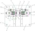
Fig. 1 is a front view of the present invention.
Fig. 2 is a top view of the present invention.
The specific implementation mode is as follows:
the present invention will be described in detail with reference to specific embodiments below:
as shown in fig. 1 and 2, the fixed-width cutting mechanism for solid wood composite floor comprises a base 1, a support table 12, limiting plates 2, a conveying cutting table 3, a positioning plate 4, adjustable plates 5, bolts 51, screws 52, threaded sleeves 53, a positioning block 54, a driving motor 6, a supporting column 7, a saw blade 8 and a transmission shaft 81, wherein the support table 2 is fixedly arranged on the base 1, the two limiting plates 2 are vertically and symmetrically arranged on the base 1 and the support table 12, a cutting area 21 is formed between the two limiting plates 2, the adjustable plates 5 are provided with oblong holes 56, the two adjustable plates 5 are respectively slidably arranged on two sides of the top of the support table 12, the positioning block 4 is fixedly arranged at the outer ends of the adjustable plates 5, the bolts 51 penetrate through the oblong holes 56 to press and fix the adjustable plates 5 on the support table 12, the driving motor 6 is fixedly arranged on the adjustable plates 5, the threaded sleeves 53 are fixedly arranged on the bottom surface of the support table 12, screw thread transmission is installed on swivel nut 53 in screw rod 52, screw rod 52 outer end passes through the bearing and rotates and install on locating piece 54, the both ends fixed mounting of transmission cutting bed 3 is on the interior face of limiting plate 2, support column 7 is arranged in cutting area 21, and the upper and lower both ends of support column 7 respectively with transmission cutting bed 3, base 1 fixed connection, transmission shaft 81 passes through the bearing and rotates limiting plate 2, it is used for compressing tightly fixed positioning bolt 22 with the bearing to go back the spiro union installation on the limiting plate 2, 8 fixed mounting of saw bit are in transmission shaft 81 the inner, adjustable breach 31 of two parallels has been seted up on the transmission cutting bed 3, the size that 8 upper ends of saw bit surpass adjustable breach 31 is 5cm ~ 10 cm.
Aiming at the actual cutting use requirement of the dimension of the wood floor, the width of the adjustable notch 31 is set to be 8-10 cm.
In addition, in order to facilitate the operator to rotate the screw rod 52, a hand wheel 55 is fixedly arranged at the outer end of the screw rod 52.
In order to fix the cutting mechanism on a fixing frame of a floor cutting production line, a countersunk head threaded hole 11 is formed in the base 1.
Firstly loosening and loosening the bolt 51, rotating the screw rod 52 to drive the adjustable plate 5 and the support table 12 to move left and right relatively to adjust the width of the blank plate, namely adjusting the position of the saw blade 8 at the adjustable notch 31, measuring the distance between the two saw blades 8 through a scale, after the adjustment is finished, screwing the screw rod 52, fixing the adjustable plate 5 on the support table 12, starting the two driving motors 6 to drive the saw blades 8 to rotate, namely cutting the blank plate, in order to avoid potential safety hazards, grabbing the blank plate by a mechanical gripper to perform cutting treatment, cutting the rough edges on two sides of the blank plate by the cutting mechanism, reserving the plate in the middle, realizing one-step forming of width-fixed cutting, and having the advantage of high production efficiency.
It is to be emphasized that: it will be evident to those skilled in the art that the utility model is not limited to the details of the foregoing illustrative embodiments, and that the present invention may be embodied in other specific forms without departing from the spirit or essential attributes thereof. The present embodiments are therefore to be considered in all respects as illustrative and not restrictive, the scope of the utility model being indicated by the appended claims rather than by the foregoing description, and all changes which come within the meaning and range of equivalency of the claims are therefore intended to be embraced therein.
Claims (4)
1. The utility model provides a solid wood composite floor decides wide cutting mechanism which characterized in that: the cutting table comprises a base (1), a support table (12), limiting plates (2), a conveying cutting table (3), a positioning plate (4), an adjustable plate (5), a bolt (51), a screw rod (52), a threaded sleeve (53), a positioning block (54), a driving motor (6), a supporting column (7), a saw blade (8) and a transmission shaft (81), wherein the support table (12) is fixedly arranged on the base (1), the two limiting plates (2) are vertically and symmetrically arranged on the base (1) and the support table (12), a cutting area (21) is formed between the two limiting plates (2), a long circular hole (56) is formed in the adjustable plate (5), the two adjustable plates (5) are respectively and slidably arranged on two sides of the top of the support table (12), the positioning plate (4) is fixedly arranged at the outer end of the adjustable plate (5), and the bolt (51) penetrates through the long circular hole (56) to tightly press and fix the adjustable plate (5) on the support table (12), the utility model discloses a cutting machine, including driving motor (6), swivel nut (53), support platform (12), support post (7), support post (21), support post (7), saw bit (8), saw bit (3) and saw bit (3), driving motor (6) fixed mounting is on adjustable board (5), swivel nut (53) fixed mounting is on the bottom surface of support platform (12), screw rod (52) inner screw thread transmission is installed on swivel nut (53), screw rod (52) outer end is passed through the bearing and is rotated and install on locating piece (54), the both ends fixed mounting of transmission cutting bed (3) is on the interior face of limiting plate (2), cutting area (21) is arranged in to support post (7), and the upper and lower both ends of support post (7) respectively with transmission cutting bed (3), base (1) fixed connection, transmission shaft (81) rotate limiting plate (2) through the bearing, it is used for compressing tightly fixed positioning bolt (22) with the bearing to go back the spiro union installation on limiting plate (2), saw bit (8) fixed mounting is in transmission shaft (81) the inner, set up two parallel adjustable breachs (31) on the transmission cutting bed (3), the size of the upper end of the saw blade (8) exceeding the adjustable notch (31) is 5 cm-10 cm.
2. The fixed-width cutting mechanism for solid wood composite floors according to claim 1, characterized in that: the width of the adjustable notch (31) is set to be 8-10 cm.
3. The fixed-width cutting mechanism for solid wood composite floors according to claim 1, characterized in that: and a hand wheel (55) is fixedly arranged at the outer end of the screw rod (52).
4. The fixed-width cutting mechanism for solid wood composite floors according to claim 1, characterized in that: the base (1) is provided with a countersunk head threaded hole (11).
Priority Applications (1)
| Application Number | Priority Date | Filing Date | Title |
|---|---|---|---|
| CN202121784114.1U CN215511414U (en) | 2021-08-02 | 2021-08-02 | Fixed-width cutting mechanism for solid wood composite floor |
Applications Claiming Priority (1)
| Application Number | Priority Date | Filing Date | Title |
|---|---|---|---|
| CN202121784114.1U CN215511414U (en) | 2021-08-02 | 2021-08-02 | Fixed-width cutting mechanism for solid wood composite floor |
Publications (1)
| Publication Number | Publication Date |
|---|---|
| CN215511414U true CN215511414U (en) | 2022-01-14 |
Family
ID=79788813
Family Applications (1)
| Application Number | Title | Priority Date | Filing Date |
|---|---|---|---|
| CN202121784114.1U Active CN215511414U (en) | 2021-08-02 | 2021-08-02 | Fixed-width cutting mechanism for solid wood composite floor |
Country Status (1)
| Country | Link |
|---|---|
| CN (1) | CN215511414U (en) |
Cited By (1)
| Publication number | Priority date | Publication date | Assignee | Title |
|---|---|---|---|---|
| CN116079146A (en) * | 2022-12-06 | 2023-05-09 | 石家庄博欧金属制品有限公司 | Tree-shaped casting automatic cutting device |
-
2021
- 2021-08-02 CN CN202121784114.1U patent/CN215511414U/en active Active
Cited By (2)
| Publication number | Priority date | Publication date | Assignee | Title |
|---|---|---|---|---|
| CN116079146A (en) * | 2022-12-06 | 2023-05-09 | 石家庄博欧金属制品有限公司 | Tree-shaped casting automatic cutting device |
| CN116079146B (en) * | 2022-12-06 | 2023-10-27 | 石家庄博欧金属制品有限公司 | Automatic cutting device for tree castings |
Similar Documents
| Publication | Publication Date | Title |
|---|---|---|
| CN101612748B (en) | Multi-functional hardwood floor re-notching machine | |
| CN201208770Y (en) | Auxiliary clamping device for wood planing machine | |
| CN111409123B (en) | A car floor mat cutting machine with adjustment function | |
| CN108943150A (en) | An intelligent cutting platform | |
| CN219190519U (en) | Plank chamfering equipment for furniture manufacturing | |
| CN108145239A (en) | The adjustable cutting machine of cutting angle | |
| CN213055168U (en) | Woodworking machine with double main shafts and primary and secondary saws | |
| CN2764586Y (en) | An angle adjustable cutting device | |
| CN108709852A (en) | A kind of timber/bamboo wood slicing experimental rig and test method | |
| CN206335610U (en) | A kind of wallpaper cutter of adjustable trimming size | |
| CN212096326U (en) | Wood floor surface plate slicing and marking device | |
| CN213732227U (en) | A wooden decoration material cutting device for interior decoration | |
| CN210548484U (en) | Air conditioner wind gap section bar cutting auxiliary device | |
| CN106965264A (en) | A kind of diclinic knife system of carpenter's flat plane | |
| CN209551915U (en) | A straight-cut straightening and cutting device for bamboo floor processing | |
| CN208991869U (en) | A kind of gaining machine | |
| CN207432371U (en) | A kind of sheet cutting machine | |
| CN207509388U (en) | A kind of compoiste wood floor positions trimming device | |
| CN221622474U (en) | Slitting device for processing lock catch floor | |
| CN105922373A (en) | Horizontal double-end tenon-reducing machine | |
| CN220517070U (en) | Wood board flat cutting machine capable of adjusting cutting angle | |
| CN215969203U (en) | Woodworking edge planer | |
| CN220052110U (en) | Energy-saving board production cutting device | |
| CN221603331U (en) | Slotting equipment for positioning angle square production | |
| CN218892086U (en) | Corner cut adjusting device for disc saw cutting machine |
Legal Events
| Date | Code | Title | Description |
|---|---|---|---|
| GR01 | Patent grant | ||
| GR01 | Patent grant |