CN215510661U - Fixture for machining outer shape of rotor of hydrogen return pump - Google Patents
Fixture for machining outer shape of rotor of hydrogen return pump Download PDFInfo
- Publication number
- CN215510661U CN215510661U CN202120644289.6U CN202120644289U CN215510661U CN 215510661 U CN215510661 U CN 215510661U CN 202120644289 U CN202120644289 U CN 202120644289U CN 215510661 U CN215510661 U CN 215510661U
- Authority
- CN
- China
- Prior art keywords
- rotor
- positioning table
- counter bore
- positioning
- return pump
- Prior art date
- Legal status (The legal status is an assumption and is not a legal conclusion. Google has not performed a legal analysis and makes no representation as to the accuracy of the status listed.)
- Active
Links
- UFHFLCQGNIYNRP-UHFFFAOYSA-N Hydrogen Chemical compound [H][H] UFHFLCQGNIYNRP-UHFFFAOYSA-N 0.000 title claims abstract description 30
- 229910052739 hydrogen Inorganic materials 0.000 title claims abstract description 30
- 239000001257 hydrogen Substances 0.000 title claims abstract description 30
- 238000003754 machining Methods 0.000 title description 18
- 230000000149 penetrating effect Effects 0.000 claims abstract description 6
- 238000011084 recovery Methods 0.000 claims description 6
- 238000004519 manufacturing process Methods 0.000 abstract description 2
- 238000000034 method Methods 0.000 description 24
- 230000007704 transition Effects 0.000 description 9
- 238000010586 diagram Methods 0.000 description 3
- 238000003801 milling Methods 0.000 description 2
- 239000000654 additive Substances 0.000 description 1
- 230000000996 additive effect Effects 0.000 description 1
- 230000009286 beneficial effect Effects 0.000 description 1
- 238000003825 pressing Methods 0.000 description 1
Images



Landscapes
- Details And Applications Of Rotary Liquid Pumps (AREA)
- Rotary Pumps (AREA)
Abstract
The utility model discloses a shape processing clamp for a hydrogen return pump rotor, which relates to the technical field of clamp manufacturing and comprises a base provided with a positioning table, wherein the positioning table is provided with a counter bore positioning table, and the counter bore positioning table is provided with two first threaded holes which are provided with first bolts in a penetrating way; the counter bore positioning table is composed of two bosses which are symmetrically arranged, and the two first threaded holes are symmetrically arranged on the two bosses respectively. Compared with the prior art, the utility model can solve the problem of poor stability of the processing precision of the curved surface appearance of the rotor body of the existing hydrogen return pump rotor.
Description
Technical Field
The utility model relates to the technical field of clamp manufacturing, in particular to an external curved surface machining clamp for a hydrogen return pump rotor.
Background
As shown in fig. 1, the hydrogen return pump rotor 1A includes a rotor body 10A having an outer edge provided with a splayed curved surface, two process holes 102A are provided in the rotor body 10A, a process transition hole 104A is provided between the two process holes 102A, and splayed positioning counter bores respectively communicating with the two process holes 102A and the process transition hole 104A are provided at both ends of the rotor body 10A. The end faces at two ends of the rotor body, the inner wall and the bottom face of the positioning counter bore, the two process holes, the process transition hole and the appearance curved surface of the rotor body are required to be processed according to design requirements; the current machining method of the rotor of the hydrogen return pump comprises the following steps: 1. placing a vice on a milling center, placing a hydrogen return pump rotor on the vice, positioning by using the end face of one end of a rotor body of the hydrogen return pump rotor, clamping the exterior curved surface of the rotor body by using the vice, and processing the end face of the other end of the rotor body, the inner wall and the bottom surface of a positioning counter bore, two process holes and a process transition hole; 2. and (3) replacing the surface of the rotor body of the hydrogen return pump rotor, placing the surface on a rotor external milling fixture to position the positioning counter bore at one end of the processed rotor body, pressing the unprocessed end face at the other end of the rotor body, and finely milling the external curved surface of the rotor body. This additive approach suffers from the following problems: 1. because the end face of one end of the rotor body and the inner wall and the bottom face of the positioning counter bore are processed after the appearance curved surface of the rotor body is clamped by the vice, the stability of the dimensional accuracy of the end face of one end of the processed rotor body and the inner wall and the bottom face of the positioning counter bore is poor; 2. because the processing of the curved surface shape of the outer edge of the rotor body takes the positioning counter bore at one end of the processed rotor body as positioning, the stability of the dimensional accuracy of the rotor body is influenced because the stability of the dimensional accuracy of the rotor body is poor.
SUMMERY OF THE UTILITY MODEL
The utility model aims to provide a machining clamp for the shape of a rotor of a hydrogen return pump, which aims to solve the problem of poor stability of machining precision of the curved surface shape of a rotor body of the conventional hydrogen return pump rotor.
The technical scheme adopted by the utility model for solving the technical problem is as follows: the machining clamp for the shape of the hydrogen return pump rotor comprises a base provided with a positioning table, wherein a counter bore positioning table is arranged on the positioning table, and two first threaded holes which are provided with first bolts in a penetrating mode are formed in the counter bore positioning table.
In the above technical solution of the clamp for processing the shape of the hydrogen return pump rotor, a more specific technical solution may also be: the counter bore positioning table is composed of two bosses which are symmetrically arranged, and the two first threaded holes are symmetrically arranged on the two bosses respectively.
Further: the outer sides of the two bosses are respectively provided with arc-shaped surfaces which are symmetrically arranged, and each arc-shaped surface is perpendicular to the upper end surface of the positioning table.
Further: the first bolt is a hexagon socket head cap screw.
Due to the adoption of the technical scheme, compared with the prior art, the utility model has the following beneficial effects: 1. the shape processing clamp for the hydrogen return pump rotor can be used for processing the end surface of the positioning end of the rotor body of a hydrogen return pump rotor blank, the inner wall and the bottom surface of the first positioning counter bore and the shape curved surface; the positioning table of the hydrogen-returning pump rotor appearance machining clamp base is provided with a counter bore positioning table, and the counter bore positioning table is provided with two first threaded holes which are provided with first bolts in a penetrating way; when the positioning device works, the second positioning counter bore of the positioning and clamping end of the rotor body of the hydrogen return pump rotor blank which is not processed can be sleeved on the counter bore positioning table, and the rotor body is fixed on the positioning table of the base by screwing the first bolt; when the shape machining clamp for the rotor of the hydrogen recovery pump is placed on the milling center, the machining of the end face of the positioning end of the rotor body of a blank of the rotor of the hydrogen recovery pump, the inner wall and the bottom face of the first positioning counter bore and the shape curved surface can be completed by one-time clamping, the relevant position degree size is ensured, the relevant coaxiality and the relevant verticality requirements are ensured, the original two processes are combined into one process, the machining stability of the size precision and the tolerance precision is improved, and the machining efficiency is also improved; 2. meanwhile, an accurate positioning reference is provided for machining the other end of the rotor body of the hydrogen return pump rotor blank.
Drawings
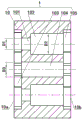
Fig. 1 is a schematic structural view of a hydrogen return pump rotor of the present invention.
Fig. 2 is a schematic structural diagram of a hydrogen return pump rotor blank according to an embodiment of the utility model.
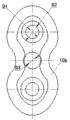
Fig. 3 is a right side view of fig. 2.
Fig. 4 is a left side view of fig. 2.
Fig. 5 is a schematic structural diagram of an embodiment of the present invention.
Fig. 6 is a schematic structural diagram of a base according to an embodiment of the present invention.
Fig. 7 is a top view of fig. 6.
Fig. 8 is a perspective view of a base of an embodiment of the present invention.
Detailed Description
The utility model is described in further detail below with reference to the accompanying drawings:
in the embodiment, a hydrogen-returning pump rotor is firstly manufactured into a hydrogen-returning pump rotor blank 1 as shown in fig. 2, fig. 3 and fig. 4, the hydrogen-returning pump rotor blank 1 comprises a rotor body 10 provided with a positioning end and a positioning and clamping end, the outer edge of the rotor body 10 is provided with a splayed outer curved surface, two process holes 102 are arranged in the rotor body 10, and a process transition hole 104 is arranged between the two process holes 102; a first positioning counter bore 105 which is respectively communicated with the two process holes 102 and the process transition hole 104 and is arranged in a splayed manner is arranged at the positioning end of the rotor body 10, a second positioning counter bore 103 which is communicated with the process transition hole 104 and is arranged in a splayed manner is arranged at the positioning and clamping end of the rotor body 10, the second positioning counter bore 103 is respectively communicated with the process holes 102 through mounting holes 101, the diameter D1 of the mounting holes 101 is smaller than the diameter D2 of the process holes 102, and the inner diameter of the process transition hole 104 is the diameter D3 of the process transition hole; then, the end face 10b of the positioning end of the rotor body 10 of the hydrogen return pump rotor blank 1, the inner wall and the bottom face of the first positioning counter bore 105 and the outer curved surface are machined by using the hydrogen return pump rotor outer shape machining fixture.
As shown in fig. 5, the shape processing fixture for the rotor of the hydrogen recovery pump comprises a base 3 provided with a positioning table 31, a counter bore positioning table 32 is arranged on the positioning table 31, the counter bore positioning table 32 of the embodiment is provided with two bosses which are symmetrically arranged, the two bosses are a boss 321 and a boss 322 respectively, the projections of the boss 321 and the boss 322 on the horizontal plane are symmetrically arranged by a central line MN, the outer sides of the two bosses are provided with arc surfaces which are symmetrically arranged respectively, the two arc surfaces are an arc surface 3211 at the outer side of the boss 321 and an arc surface 3221 at the outer side of the boss 322 respectively, so as to ensure the positioning accuracy of the counter bore positioning table 32; each arc-shaped surface is perpendicular to the upper end surface of the positioning table 31, and the arc-shaped surface 3211 of the boss 321 and the arc-shaped surface 3221 of the boss 322 are perpendicular to the upper end surface of the positioning table 31, so that the positioning accuracy of the counter bore positioning table 32 is improved; two first threaded holes are formed in the counter bore positioning table 32, the two first threaded holes are symmetrically formed in the boss 321 and the boss 322 respectively, and the projections of the two first threaded holes on the horizontal plane are symmetrically formed by a center line MN; each first threaded hole is provided with a first bolt 2 in a penetrating way, and the first bolt 2 in the embodiment is a hexagon socket head cap screw.
The hydrogen-returning pump rotor appearance machining clamp can be used for machining the end face 10b of the positioning end of the rotor body 10 of the hydrogen-returning pump rotor blank 1, the inner wall and the bottom face of the first positioning counter bore 105 and an appearance curved surface; because the positioning table 31 of the hydrogen-returning pump rotor appearance machining clamp base is provided with the counter bore positioning table 32, and the counter bore positioning table 32 is provided with two first threaded holes which are all provided with the first bolts 2 in a penetrating way; during working, the second positioning counter bore 103 at the positioning and clamping end of the rotor body 10 of the hydrogen-returning pump rotor blank 1 which is not machined can be sleeved on the counter bore positioning table 32, and the rotor body 10 is fixed on the positioning table 31 of the base 3 by screwing the first bolt 2; when the shape processing clamp of the rotor of the hydrogen recovery pump is placed on the milling center, the end surface 10b of the positioning end of the rotor body of a blank of the rotor of the hydrogen recovery pump, the inner wall and the bottom surface of the first positioning counter bore 105 and the shape curved surface can be processed by one-time clamping, the relevant position degree size is ensured, the relevant coaxiality and the relevant verticality requirement are ensured, the original two processes are combined into one process, the processing stability of the size precision and the tolerance precision is improved, and the processing efficiency is also improved; meanwhile, an accurate positioning reference is provided for machining the other end of the rotor body of the hydrogen return pump rotor blank.
Claims (2)
1. The utility model provides a hydrogen return pump rotor appearance adds clamping apparatus which characterized in that: the positioning device comprises a base provided with a positioning table, wherein a counter bore positioning table is arranged on the positioning table, and two first threaded holes which are provided with first bolts in a penetrating mode are formed in the counter bore positioning table; the counter bore location platform is two bosses that are the symmetry and set up, two first screw hole symmetry respectively sets up two on the boss, two the outside of boss is equipped with the arcwall face that is the symmetry and sets up respectively, every the arcwall face all with the perpendicular setting is personally submitted to the upper end of location platform.
2. The shape processing jig for a rotor of a hydrogen recovery pump according to claim 1, characterized in that: the first bolt is a hexagon socket head cap screw.
Priority Applications (1)
| Application Number | Priority Date | Filing Date | Title |
|---|---|---|---|
| CN202120644289.6U CN215510661U (en) | 2021-03-30 | 2021-03-30 | Fixture for machining outer shape of rotor of hydrogen return pump |
Applications Claiming Priority (1)
| Application Number | Priority Date | Filing Date | Title |
|---|---|---|---|
| CN202120644289.6U CN215510661U (en) | 2021-03-30 | 2021-03-30 | Fixture for machining outer shape of rotor of hydrogen return pump |
Publications (1)
| Publication Number | Publication Date |
|---|---|
| CN215510661U true CN215510661U (en) | 2022-01-14 |
Family
ID=79801110
Family Applications (1)
| Application Number | Title | Priority Date | Filing Date |
|---|---|---|---|
| CN202120644289.6U Active CN215510661U (en) | 2021-03-30 | 2021-03-30 | Fixture for machining outer shape of rotor of hydrogen return pump |
Country Status (1)
| Country | Link |
|---|---|
| CN (1) | CN215510661U (en) |
-
2021
- 2021-03-30 CN CN202120644289.6U patent/CN215510661U/en active Active
Similar Documents
| Publication | Publication Date | Title |
|---|---|---|
| CN103949909B (en) | A kind of CNC processes spherical parts built-up jig and clamping method | |
| CN206662766U (en) | Aerial blade fixture | |
| CN106041573A (en) | Combined clamp for machining holes in multiple faces through CNC and clamping method | |
| CN213969977U (en) | Universal tool for tapping of connecting plate | |
| CN220144797U (en) | Tool for turning multi-angle elbow die forging joint | |
| CN218110050U (en) | Adjustable leveling fixture for drilling and milling of irregularly shaped workpieces | |
| CN217619115U (en) | Clamping tool for processing two ends of shaft part | |
| CN113020918B (en) | Processing method of hydrogen return pump rotor | |
| CN217194118U (en) | Swash plate machining tool | |
| CN210967348U (en) | A frock clamp for high accuracy inner key groove line cutting process | |
| CN105500058B (en) | A kind of CNC processing bool special fixtures and clamping method | |
| CN103769909A (en) | Clamp special for lifting lug outer contour milling | |
| CN215200736U (en) | Back hydrogen pump rotor plane adds clamping apparatus | |
| CN214557570U (en) | Processing tool for threaded bottom hole of ABS retaining block | |
| CN224058878U (en) | Clamp for electric spark machining of end face inclined hole of oil supply ring communicated with closed cavity | |
| CN220533031U (en) | Frock clamp in counter sinking hole in dysmorphism part processing inclined plane | |
| CN207104641U (en) | Latch hook is ground notch fixture | |
| CN221495112U (en) | Positioning tool for milling pipe joint | |
| CN220497665U (en) | Riveting fixture clamp capable of accurately limiting three-dimensional direction | |
| CN221159426U (en) | Special tool of aviation part milling machine processing | |
| CN224196331U (en) | A tooling for a precise positioning and rapid clamping multi-station vertical machining center for milling, drilling, and boring. | |
| CN223325894U (en) | Die forging bending joint processing tool | |
| CN217122500U (en) | Robot joint machining clamp | |
| CN222643863U (en) | Tool clamp for machining axle center shell | |
| CN222520636U (en) | Carbon fiber gas cylinder tooling |
Legal Events
| Date | Code | Title | Description |
|---|---|---|---|
| GR01 | Patent grant | ||
| GR01 | Patent grant |