CN215505652U - Quick replacement device convenient to change sand filter material - Google Patents
Quick replacement device convenient to change sand filter material Download PDFInfo
- Publication number
- CN215505652U CN215505652U CN202121435286.8U CN202121435286U CN215505652U CN 215505652 U CN215505652 U CN 215505652U CN 202121435286 U CN202121435286 U CN 202121435286U CN 215505652 U CN215505652 U CN 215505652U
- Authority
- CN
- China
- Prior art keywords
- filter
- replacement device
- quick replacement
- support
- filter tank
- Prior art date
- Legal status (The legal status is an assumption and is not a legal conclusion. Google has not performed a legal analysis and makes no representation as to the accuracy of the status listed.)
- Expired - Fee Related
Links
Images




Landscapes
- Filtration Of Liquid (AREA)
Abstract
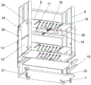
The utility model relates to a quick replacement device convenient for replacing a sand filter material, which comprises a filter tank and a filter element, wherein a plurality of filter boxes are arranged inside the filter tank, a moving frame is arranged outside the filter tank, rollers are arranged at the bottom of the moving frame, a plurality of layers of partition plates and a plurality of lifting assemblies are arranged on the moving frame, a plurality of support rods are arranged on the partition plates, pulleys are arranged on the support rods, support plates are movably connected to two sides of the moving frame, support legs are movably connected to the lower surfaces of the support plates, the moving frame and the partition plates on the moving frame can enable the filter boxes to be more conveniently and easily replaced, and the filter boxes can be directly placed on the partition plates after being disassembled, so that time and labor are saved, the support plates can be horizontally placed, and the filter boxes with higher positions can be conveniently disassembled by workers due to the support of the support legs.
Description
Technical Field
The utility model relates to the technical field of sand filtration equipment, in particular to a quick replacement device convenient for replacing a sand filtration material.
Background
The sand filtration is a water filtration treatment process using natural quartz sand, manganese sand and anthracite as a filter element, and in the actual use process, the sand filtration is mainly used for filtering large-particle solid impurities and colloid in water to clarify the water, and the manganese sand also has the function of removing heavy metals in the water, and the application number CN201696959. X discloses a sand filtration device which can disinfect sewage, because the quartz sand is usually arranged in a tank, the quartz sand needs to be replaced after a period of use, the process of replacing the quartz sand is troublesome, the quartz sand in the container is taken out firstly, the quartz sand at the corners is removed as clean as possible, then the container needs to be washed with water, the quartz sand which is not easy to be cleaned in the container is cleaned, and the quartz sand is taken out manually, which is very inconvenient, and the height of the sand filtration tank is high, and workers are not always enough when the quartz sand is replaced, the taking-out of the quartz sand is influenced.
SUMMERY OF THE UTILITY MODEL
Technical problem to be solved
Aiming at the defects of the prior art, the utility model provides a quick replacing device for replacing a sand filter material conveniently.
(II) technical scheme
In order to achieve the purpose, the utility model provides the following technical scheme: a quick replacement device convenient for replacing sand filter materials comprises a filter tank and a filter element, wherein a plurality of filter boxes are arranged inside the filter tank, the filter element is arranged inside the filter box, water holes are formed in the upper end and the lower end of the filter box, one end of the filter box penetrates through the filter tank and is connected with the filter tank through a flange, a plurality of support bars are arranged on the inner wall of the filter tank, a moving frame is arranged outside the filter tank, rollers are arranged at the bottom of the moving frame, a plurality of layers of partition plates and a plurality of lifting components are arranged on the moving frame, a plurality of support rods are arranged on the partition plates, pulleys are arranged on the support rods, a sliding groove is formed in each partition plate, part of the support rods are arranged in an n shape, the bottom ends of the part of the support rods are arranged in the sliding groove, the lower surfaces of the support rods are connected with the pulleys, and the other support rods are fixedly connected with the partition plates, and the top end is connected with the pulley, the two sides of the moving frame are movably connected with the supporting plates, the lower surfaces of the supporting plates are movably connected with the supporting legs, and the supporting plates are provided with limiting strips corresponding to the supporting legs.
Preferably, a base is arranged below the moving frame, the moving frame is connected with the base in a sliding mode, one group of lifting assemblies are arranged on the base, and the rollers are arranged on the lower surface of the base. The movable frame can be lifted and lowered, and can be used for adjusting the position of the partition plate, so that all the filter boxes can be taken out easily.
Preferably in the further, the lifting component comprises a lifting screw rod, a rocker, two driving blocks and a plurality of linkage rods, the driving blocks are in threaded connection with the lifting screw rod, two ends of the lifting screw rod are rotatably connected with the movable frame, one end of the lifting screw rod is connected with the rocker, one end of the linkage rod is connected with the partition plate or the movable frame, and the other end of the linkage rod is connected with the driving blocks. The lifting component can easily move the partition plate and the movable frame, so that the supporting rods or the rollers on the partition plate can contact the filter box.
Preferably, a plurality of guide rods are arranged on two sides of the lifting screw rod, the guide rods penetrate through the driving block and are in sliding connection with the driving block, and the guide rods are fixedly connected with the moving frame. The guide rod is used for supporting the driving block.
In a further preferred mode, the base is provided with a plurality of supporting columns, the supporting columns are provided with threads and are in threaded connection with the base, and the top ends of the supporting columns are provided with rotating blocks. The support column is used for fixing the movable frame and the base.
Preferably in further, be provided with the bar hole in the backup pad, be provided with a plurality of fixed column on the removal frame, the frame sliding connection is removed to the one end of fixed column, the other end of fixed column sets up to the T shape, and this end passes the bar hole. The fixed column is rotated a certain angle after being inserted into the strip-shaped hole, so that the supporting plate can be easily fixed.
In a further preferred mode, the support plate is provided with a plurality of support plates, one of the support plates is connected with the base, the other support plate is connected with the movable frame, the support legs on the support plates are arranged in a hollow mode, the extension rods are arranged inside the support legs, the top ends of the extension rods are movably connected with the support plates, and the support legs are provided with locking bolts. The support plates allow workers to reach the filter boxes at different heights, and the support legs with the extension rods can change the length so that the height of the support plates can be raised together with the moving frame.
In a further preferred embodiment, the support plates decrease in length from top to bottom. The higher backup pad of workman mountain-climbing ratio of being convenient for.
(III) advantageous effects
Compared with the prior art, the utility model provides a quick replacing device convenient for replacing a sand filter material, which has the following beneficial effects:
in the utility model, the filter element is arranged in the filter box, one end of the filter box penetrates through the filter tank and is connected by a flange to ensure the sealing property, when the filter element needs to be replaced, the movable frame can be directly pushed to lean against the filter tank, then a worker removes a bolt for connecting the filter tank and the filter box and takes out a part of the filter box, so that the filter box is arranged above the supporting rod and is arranged on the supporting rod, a pulley is arranged between the fixed supporting rod and the filter box, and a pulley is connected below the movable supporting rod, so that when the filter box is taken out from the filter tank, the filter box is easier and more convenient, after the filter box is taken out, the movable frame is pushed away, after a new filter box is replaced, the filter box can be directly pushed into the filter tank and then is fixed, because the filter element is replaced by replacing the filter box, a plurality of steps can be saved, and the replacing speed can also be increased, change the filter box through removing the frame, can make the change of filter box become very simple, it is quick, the height of baffle and bracing piece can be adjusted to lifting unit, a canister and filter box for adapting to not unidimensional, when the filter box is higher, pull down the one end of backup pad from removing the frame, and launch the supporting leg, put down the backup pad at last, thus, the workman can stand and go to dismantle in the backup pad and the higher filter box of mounted position, the process of launching the backup pad and accomodating the backup pad is very simple, can not too influence the filter box with the speed of changing.
Drawings
FIG. 1 is a schematic view of the overall structure of the present invention;
FIG. 2 is a schematic structural view of a movable frame according to the present invention;
FIG. 3 is a schematic sectional view of the movable frame of the present invention;
FIG. 4 is a schematic view of the construction of a canister according to the present invention;
FIG. 5 is a schematic view of the structure of the separator according to the present invention;
FIG. 6 is a schematic view showing the construction of the support plate and the support leg according to the present invention.
In the figure: 1. a filter tank; 2. a filter element; 3. a filter box; 4. water passing holes; 5. a supporting strip; 6. a movable frame; 7. a roller; 8. a partition plate; 9. a support bar; 10. a pulley; 11. a chute; 12. a support plate; 13. supporting legs; 14. a limiting strip; 15. a base; 16. lifting a screw rod; 17. a rocker; 18. a drive block; 19. a linkage rod; 20. a guide bar; 21. a support pillar; 22. rotating the block; 23. a strip-shaped hole; 24. fixing a column; 25. an extension pole; 26. and locking the bolt.
Detailed Description
The technical solutions in the embodiments of the present invention will be clearly and completely described below with reference to the drawings in the embodiments of the present invention, and it is obvious that the described embodiments are only a part of the embodiments of the present invention, and not all of the embodiments. All other embodiments, which can be derived by a person skilled in the art from the embodiments given herein without making any creative effort, shall fall within the protection scope of the present invention.
Example 1:
referring to fig. 1-6, a quick replacement device for replacing sand filter material conveniently comprises a filter tank 1 and a filter element 2, wherein a plurality of filter boxes 3 are arranged inside the filter tank 1, the filter element 2 is arranged inside the filter boxes 3, water holes 4 are arranged at the upper end and the lower end of each filter box 3, one end of each filter box 3 penetrates through the filter tank 1 and is connected with the filter tank 1 through a flange, a plurality of support bars 5 are arranged on the inner wall of the filter tank 1, a movable frame 6 is arranged outside the filter tank 1, rollers 7 are arranged at the bottom of the movable frame 6, a plurality of layers of partition plates 8 and a plurality of lifting assemblies are arranged on the movable frame 6, a plurality of support rods 9 are arranged on each partition plate 8, pulleys 10 are arranged on the support rods 9, a chute 11 is arranged on each partition plate 8, part of the support rods 9 are n-shaped, and the bottom ends of the part of the support rods 9 are arranged in the chute 11, and the lower surface is connected with pulley 10, other bracing piece 9 and baffle 8 fixed connection, and the top is connected with pulley 10, the equal swing joint in both sides that removes frame 6 has backup pad 12, backup pad 12 lower surface swing joint has supporting leg 13, be provided with spacing 14 that corresponds with supporting leg 13 in the backup pad 12.
In this embodiment, a base 15 is disposed below the movable frame 6, the movable frame 6 is slidably connected to the base 15, a set of lifting assemblies is disposed on the base 15, and the rollers 7 are disposed on the lower surface of the base 15. The base 15 is slidably connected to the movable frame 6, and the movable frame 6 can be raised by the lifting assembly, so that the filter boxes 3 on the canister 1, which are blocked by the lifting assembly, are not blocked, and all the filter boxes 3 can be taken out.
In this embodiment, the lifting assembly includes a lifting screw 16, a rocker 17, two driving blocks 18 and a plurality of linkage rods 19, the driving blocks 18 are in threaded connection with the lifting screw 16, two ends of the lifting screw 16 are rotatably connected with the movable frame 6, one end of the lifting screw is connected with the rocker 17, one end of the linkage rod 19 is connected with the partition plate 8 or the movable frame 6, and the other end of the linkage rod is connected with the driving blocks 18. The screw thread on the lifting screw rod 16 is a bidirectional screw thread, the lifting screw rod 16 is driven to rotate through the rocker 17, the driving blocks 18 are close to each other, the driving blocks 18 drive the partition plate 8 to ascend by means of the linkage rod 19, so that the partition plate 8 or the movable frame 6 can move, and the supporting rod 9 on the partition plate 8 can accurately support the filter box 3.
In this embodiment, a plurality of guide rods 20 are disposed on both sides of the lifting screw 16, the guide rods 20 penetrate through the driving block 18 and are slidably connected with the driving block 18, and the guide rods 20 are fixedly connected with the movable frame 6. The guide rod 20 may be used to support the drive block 18.
In this embodiment, the bottom of the movable frame 6 is provided with a plurality of supporting columns 21, the supporting columns 21 are provided with threads, the supporting columns 21 are in threaded connection with the movable frame 6, and the top ends of the supporting columns 21 are provided with rotating blocks 22. The rotation block 22 rotates the support post 21, so that the support post 21 contacts the ground to fix the base 15, and the base 15 does not move.
In this embodiment, be provided with bar hole 23 on the backup pad 12, be provided with a plurality of fixed column 24 on the removal frame 6, 6 sliding connection of frame are removed to the one end of fixed column 24, the other end of fixed column 24 sets up to the T shape, and this end passes bar hole 23. One end of the fixing column 24T is inserted into the strip-shaped hole 23, then the fixing column is rotated by a certain angle, so that the supporting plate 12 can be fixed, when the supporting plate 12 is connected with the base, the strip-shaped hole 23 on the supporting plate is longer, the fixing column 24 can slide in the strip-shaped hole 23, and the supporting plate 12 cannot block the moving frame 6 to move.
In this embodiment, the supporting plate 12 is provided with a plurality of supporting plates, one supporting plate 12 is connected with the base 15, the other supporting plates 12 are connected with the movable frame 6, the supporting legs 13 on the supporting plate 12 are hollow, an extension rod 25 is arranged inside the supporting legs 13, the top end of the extension rod 25 is movably connected with the supporting plate 12, and the supporting legs 13 are provided with locking bolts 26. The support plates 12 allow a person to reach the filter boxes 3 of different heights, the extension rods 25 allow the support legs 13 to be extended and fixed by the locking bolts 26, and the height of the support plates 12 can be changed, so that the support plates 12 can be used after the height of the moving frame 6 is changed.
In the present embodiment, the length of the supporting plate 12 decreases from top to bottom. The supporting plate 12 with a higher position can be conveniently climbed by people, the supporting legs 13 on the supporting plate 12 with a higher position can be placed in the supporting plate 12 by slotting the supporting plate 12, or the width of the supporting plate 12 is changed, so that a plurality of supporting plates 12 can be unfolded simultaneously.
Example 2:
referring to fig. 1-6, when the filter cartridge 2 is used, the service life of the filter cartridge 2 is used up, and the filter cartridge 2 needs to be replaced, the movable frame 6 is moved to the canister 1, then the rotating block 22 is rotated to rotate the supporting post 21, the bottom end of the supporting post 21 contacts the ground to fix the movable frame 6, after the movable frame 6 is fixed, a worker takes down the bolt connected with the filter cartridge 3, the filter cartridge 3 is partially drawn out by using a handle, the filter cartridge 3 is positioned above the supporting rod 9, then the rocker 17 corresponding to the partition plate 8 below the filter cartridge 3 is rotated, the rocker 17 drives the lifting screw 16 to rotate, the driving blocks 18 are close to each other, the driving blocks 18 drive the partition plate 8 to ascend by virtue of the linkage rod 19, further the pulley 10 on the fixed supporting rod 9 contacts the filter cartridge 3, the top ends of the other supporting rods 9 contact the filter cartridge 3, then the filter cartridge 3 is pulled by the handle to move, the movable supporting rod 9 moves along with the filter cartridge 3, the pulley 10 on the fixed support rod 9 rotates along with the movement of the filter box 3, the pulley 10 enables the filter box 3 or the support rod 9 to move more easily, after all the filter boxes 3 are taken out, the rotating block 22 is rotated to separate the support column 21 from the ground, so that the movable frame 6 can be easily pushed to move, the movable frame 6 is pushed to other places, the filter box 3 on the movable frame 6 is pushed to the side surface of the filter tank 1 after being replaced, the filter box 3 on the movable frame 6 is aligned to the corresponding position on the filter tank 1, the movable frame 6 is fixed by the support column 21, the filter box 3 is directly pushed to move to enter the filter tank 1, after most of the filter box 3 is pushed into the filter tank 1, the position on the filter box 3 connected with the filter tank 1 is blocked, at this time, the rocker 17 is rotated reversely, the driving block 18 is far away through the lifting screw rod 16, and the partition plate 8 and the support rod 9 descend, the filter boxes 3 are smoothly inserted into the filter tank 1, after all the filter boxes 3 are fixed on the filter boxes 3, the rocker 17 at the lowest part of the movable frame 6 is rotated, the movable frame 6 is lifted or shortened through the lifting screw rod 16, the driving block 18 and the linkage rod 19, and then the filter boxes 3 which are blocked by the lifting assembly and cannot be replaced are replaced until all the filter boxes 3 are replaced.
Example 3:
referring to fig. 1 to 6, when a lot of impurities are accumulated in a filter element 2 in a filter tank 1 and a filter box 3 needs to be replaced, a movable frame 6 is moved to the side of the filter tank 1, the movable frame 6 is fixed by a support post 21, the filter box 3 is disassembled, the filter box 3 can be taken down and a part of the filter box 3 is drawn out, the filter box 3 is positioned above a support rod 9, a lifting screw 16, a driving block 18 and a linkage rod 19 are driven by a rocker 17 to lift a partition plate 8, the support rod 9 supports the filter box 3, a pulley 10 enables the filter box 3 to move more easily, when the filter box 3 is replaced, if a worker is inconvenient to detach the filter box 3 due to the fact that the height of the filter box 3 is high, a fixing column 24 is rotated to enable one end of a T shape of the fixing column 24 to be aligned with a strip-shaped hole 23, the fixing column 24 can pass through the strip-shaped hole 23, and the fixing column 24 passes through the strip-shaped hole 23, put down the backup pad 12, and expand supporting leg 13, spacing strip 14 makes supporting leg 13 can not excessive expansion, can stand people in backup pad 12 like this, the workman stands and dismantles filter box 3 in backup pad 12, if filter box 3 position can expand higher backup pad 12 in position than higher, when expanding higher backup pad 12 in position, unscrew locking bolt 26, take supporting leg 13 out from extension rod 25, make supporting leg 13 expand the back and contact ground, then through locking bolt 26 with supporting leg 13 fixed, after having changed some filter boxes 3, rotate the rocker 17 of removal frame 6 below, make removal frame 6 rise and descend through lift lead screw 16, drive block 18 and trace 19, make baffle 8 aim at the filter box 3 that does not have the change, after having changed, reverse operation, make backup pad 12, baffle 8 etc. reset can.
Although embodiments of the present invention have been shown and described, it will be appreciated by those skilled in the art that changes, modifications, substitutions and alterations can be made in these embodiments without departing from the principles and spirit of the utility model, the scope of which is defined in the appended claims and their equivalents.
Claims (8)
1. The utility model provides a quick replacement device convenient to change sand filter material, includes canister (1) and filter core (2), its characterized in that: the filter comprises a filter tank (1), a plurality of filter boxes (3) are arranged in the filter tank (1), a filter element (2) is arranged in the filter tank (3), water holes (4) are formed in the upper end and the lower end of the filter tank (3), one end of the filter tank (3) penetrates through the filter tank (1), the end of the filter tank is connected with the filter tank (1) through a flange, a plurality of support bars (5) are arranged on the inner wall of the filter tank (1), a movable frame (6) is arranged outside the filter tank (1), rollers (7) are arranged at the bottom of the movable frame (6), a plurality of layers of partition plates (8) and a plurality of lifting components are arranged on the movable frame (6), a plurality of support rods (9) are arranged on the partition plates (8), pulleys (10) are arranged on the support rods (9), a sliding groove (11) is arranged on the partition plates (8), and part of the support rods (9) are arranged in an n shape, and this part bracing piece (9) bottom sets up in spout (11), and lower surface and pulley (10) are connected, other bracing piece (9) and baffle (8) fixed connection, and top and pulley (10) are connected, the equal swing joint in both sides of removing frame (6) has backup pad (12), backup pad (12) lower surface swing joint has supporting leg (13), be provided with spacing (14) that correspond with supporting leg (13) on backup pad (12).
2. The quick replacement device of claim 1, wherein the quick replacement device is adapted to facilitate replacement of a sand filter media, and further comprises: the movable rack is characterized in that a base (15) is arranged below the movable rack (6), the movable rack (6) is connected with the base (15) in a sliding mode, a group of lifting assemblies are arranged on the base (15), and the rollers (7) are arranged on the lower surface of the base (15).
3. The quick replacement device of claim 2, wherein the quick replacement device is adapted to facilitate replacement of a sand filter media, and further comprises: the lifting assembly comprises a lifting screw rod (16), a rocker (17), two driving blocks (18) and a plurality of linkage rods (19), the driving blocks (18) are in threaded connection with the lifting screw rod (16), the two ends of the lifting screw rod (16) are rotatably connected with the movable frame (6), one end of each linkage rod is connected with the rocker (17), one end of each linkage rod (19) is connected with the partition plate (8) or the movable frame (6), and the other end of each linkage rod is connected with the driving blocks (18).
4. The quick replacement device of claim 3, wherein the quick replacement device is adapted to facilitate replacement of a sand filter media, and further comprises: the lifting screw rod (16) is characterized in that a plurality of guide rods (20) are arranged on two sides of the lifting screw rod (16), the guide rods (20) penetrate through the driving block (18) and are in sliding connection with the driving block (18), and the guide rods (20) are fixedly connected with the moving frame (6).
5. The quick replacement device of claim 2, wherein the quick replacement device is adapted to facilitate replacement of a sand filter media, and further comprises: be provided with a plurality of support column (21) on base (15), be provided with the screw thread on support column (21), support column (21) and base (15) threaded connection, the top of support column (21) is provided with turning block (22).
6. The quick replacement device of claim 1, wherein the quick replacement device is adapted to facilitate replacement of a sand filter media, and further comprises: be provided with bar hole (23) on backup pad (12), be provided with a plurality of fixed column (24) on removing frame (6), the one end of fixed column (24) removes frame (6) frame sliding connection, the other end of fixed column (24) sets up to the T shape, and this end passes bar hole (23).
7. The quick replacement device of claim 3, wherein the quick replacement device is adapted to facilitate replacement of a sand filter media, and further comprises: the supporting plate (12) is provided with a plurality of, one of them backup pad (12) and base (15) are connected, other the backup pad (12) and removal frame (6) are connected, and this part supporting leg (13) on backup pad (12) are the cavity setting, just the inside of supporting leg (13) is provided with extension rod (25), the top and backup pad (12) swing joint of extension rod (25), be provided with locking bolt (26) on supporting leg (13).
8. The quick change device of claim 7 for facilitating the change of sand filter media, wherein: the length of the supporting plate (12) is reduced from top to bottom in sequence.
Priority Applications (1)
| Application Number | Priority Date | Filing Date | Title |
|---|---|---|---|
| CN202121435286.8U CN215505652U (en) | 2021-06-25 | 2021-06-25 | Quick replacement device convenient to change sand filter material |
Applications Claiming Priority (1)
| Application Number | Priority Date | Filing Date | Title |
|---|---|---|---|
| CN202121435286.8U CN215505652U (en) | 2021-06-25 | 2021-06-25 | Quick replacement device convenient to change sand filter material |
Publications (1)
| Publication Number | Publication Date |
|---|---|
| CN215505652U true CN215505652U (en) | 2022-01-14 |
Family
ID=79810463
Family Applications (1)
| Application Number | Title | Priority Date | Filing Date |
|---|---|---|---|
| CN202121435286.8U Expired - Fee Related CN215505652U (en) | 2021-06-25 | 2021-06-25 | Quick replacement device convenient to change sand filter material |
Country Status (1)
| Country | Link |
|---|---|
| CN (1) | CN215505652U (en) |
-
2021
- 2021-06-25 CN CN202121435286.8U patent/CN215505652U/en not_active Expired - Fee Related
Similar Documents
| Publication | Publication Date | Title |
|---|---|---|
| CN117065380A (en) | Separating device for different mediums for preparation of trialkyl phosphine oxide extractant | |
| CN213081148U (en) | Polishing device with excess material collection function | |
| CN216874827U (en) | Tealeaves is produced and is turned over stir-fry device with tealeaves | |
| CN113426172A (en) | Energy-concerving and environment-protective waste water recovery processing apparatus that uses | |
| CN116871237B (en) | Silicon wafer cleaning device for production of photovoltaic power generation monocrystalline silicon wafer | |
| CN218775276U (en) | Cleaning device for processing light pollution prevention lens | |
| CN114857938B (en) | A slag removal device for high temperature furnace and use method thereof | |
| CN212284770U (en) | Quick cleaning device of crude salt | |
| CN215926629U (en) | Scaffold frame that building engineering used | |
| CN114251018A (en) | Protective fence for engineering construction | |
| CN219251811U (en) | An impurity filter device used in the process of industrial sewage treatment | |
| CN218291158U (en) | Metal product surface electroplating processing equipment | |
| CN219091427U (en) | Dust removal framework for high-temperature smoke dust filtration | |
| CN221502199U (en) | Road drainage structure | |
| CN218608435U (en) | Shallow sand filter equipment | |
| CN219481693U (en) | Recovery filter press | |
| CN223017795U (en) | A diversified drainage pump station for urban use | |
| CN213645089U (en) | Glass cleaning machine | |
| CN221061862U (en) | Loquat honey separation device | |
| CN216706883U (en) | Lubricating oil recycling device for wire cutting machine | |
| CN212319362U (en) | Portable environmental protection monitoring devices | |
| CN224100147U (en) | Plateau plant extract liquid precision filter device | |
| CN221031299U (en) | Building elevating platform convenient to adjust | |
| CN221412349U (en) | A building sewage treatment device | |
| CN221451768U (en) | Flavonoid extraction filter device |
Legal Events
| Date | Code | Title | Description |
|---|---|---|---|
| GR01 | Patent grant | ||
| GR01 | Patent grant | ||
| CF01 | Termination of patent right due to non-payment of annual fee | ||
| CF01 | Termination of patent right due to non-payment of annual fee |
Granted publication date: 20220114 |