CN215503615U - Foot drop rehabilitation auxiliary device - Google Patents
Foot drop rehabilitation auxiliary device Download PDFInfo
- Publication number
- CN215503615U CN215503615U CN202122008011.2U CN202122008011U CN215503615U CN 215503615 U CN215503615 U CN 215503615U CN 202122008011 U CN202122008011 U CN 202122008011U CN 215503615 U CN215503615 U CN 215503615U
- Authority
- CN
- China
- Prior art keywords
- fixedly connected
- box body
- wall
- foot drop
- plate
- Prior art date
- Legal status (The legal status is an assumption and is not a legal conclusion. Google has not performed a legal analysis and makes no representation as to the accuracy of the status listed.)
- Expired - Fee Related
Links
- 206010034701 Peroneal nerve palsy Diseases 0.000 title claims abstract description 22
- 230000000087 stabilizing effect Effects 0.000 claims description 4
- 230000007547 defect Effects 0.000 description 2
- 230000009286 beneficial effect Effects 0.000 description 1
- 210000003141 lower extremity Anatomy 0.000 description 1
- 238000000034 method Methods 0.000 description 1
- 230000004048 modification Effects 0.000 description 1
- 238000012986 modification Methods 0.000 description 1
- 230000000399 orthopedic effect Effects 0.000 description 1
- 238000001356 surgical procedure Methods 0.000 description 1
Images


Landscapes
- Rehabilitation Tools (AREA)
Abstract
The utility model relates to the technical field of foot drop rehabilitation, in particular to a foot drop rehabilitation auxiliary device, which comprises a box body, wherein the top of the box body is provided with an opening, a placing plate is movably connected between the front inner wall and the rear inner wall of the box body and is arranged in an L shape, a threaded rod is movably connected on the left side and the right side of the box body through a bearing, a rectangular block is sleeved on the side wall of the threaded rod, the top of the rectangular block is fixedly connected with a first fixing plate, the front wall of the first fixing plate is movably connected with a supporting plate, the rear side wall of the supporting plate, which is close to the top, is movably connected with a second fixing plate, the top of the second fixing plate is fixedly connected with the placing plate, the threaded rod is driven to rotate through rotating a vertical rod during actual use through the box body, the placing plate, the threaded rod, the rectangular block, a vertical pipe, a vertical rod and the like, so that the inclination angle of the placing plate can be adjusted according to the needs, and the inclination angle of a patient on the placing plate can be adjusted, can effectively achieve the convenient use.
Description
Technical Field
The utility model relates to a foot drop rehabilitation instrument, in particular to a foot drop rehabilitation auxiliary device.
Background
The foot drop is one of the physical signs of orthopedic surgery, two lower limbs of a patient in a sitting position naturally hang, if the foot is in a plantarflexion position and can not be actively dorsiflexed, turned inwards and outwards, the foot drop is caused, a foot drop rehabilitation auxiliary device is needed to be used for correcting in the process of treating the foot drop, when the existing partial foot drop rehabilitation auxiliary device is used, the inclination angle needs to be adjusted after the auxiliary device is lifted from the upper surface of the rehabilitation auxiliary device every time, inconvenience is brought to the patient, the height of the handrail can not be adjusted according to patients with different physiques, and therefore the problems that the use is inconvenient, the use range is low and the like are caused, and the foot drop rehabilitation auxiliary device is provided by people.
SUMMERY OF THE UTILITY MODEL
Aiming at the defects of the prior art, the utility model provides a foot drop rehabilitation assisting device, which overcomes the defects of the prior art, and effectively solves the problems that the inclination angle is adjusted after the inclination angle is adjusted from the upper surface of the rehabilitation assisting device every time, so that inconvenience is brought to patients, the height of a handrail cannot be adjusted according to patients with different physiques, the use is inconvenient, the use range is low, and the like.
In order to solve the technical problems, the utility model provides the following technical scheme:
a foot drop rehabilitation auxiliary device comprises a box body, wherein the top of the box body is provided with an opening, a placing plate is movably connected between the front inner wall and the rear inner wall of the box body, and the placing plate is arranged in an L shape;
the left side and the right side of the box body are movably connected with a threaded rod through a bearing, a rectangular block is sleeved on the side wall of the threaded rod, a first fixing plate is fixedly connected to the top of the rectangular block, a supporting plate is movably connected to the front wall of the first fixing plate, a second fixing plate is movably connected to the rear side wall of the supporting plate, which is close to the top, the top of the second fixing plate is fixedly connected with a placing plate, a shell is fixedly connected to the right side wall of the box body, the right end of the threaded rod penetrates through the inner ring of the bearing and extends into the shell, a first bevel gear is fixedly connected with the right end of the threaded rod, a vertical pipe is arranged above the shell, a vertical rod is arranged in the vertical pipe, the bottom end of the vertical rod penetrates through the shell and is movably connected with the shell, a second bevel gear is fixedly connected to the bottom of the vertical pipe, the second bevel gear is meshed with the first bevel gear, a rotary table is fixedly connected to the top of the vertical pipe, a threaded hole is formed in the right side wall, which is close to the bottom, and a bolt is arranged in the threaded hole, and the left end of the bolt extends into the vertical pipe and contacts with the vertical pipe.
As a preferred technical scheme of the utility model, the bottom of the rectangular block is fixedly connected with a first sliding block, and the bottom of the inner cavity of the box body is provided with a first sliding groove matched with the first sliding block.
As a preferred technical scheme of the utility model, the front side wall and the rear side wall of the box body are respectively and fixedly connected with a protection plate, and a stabilizing plate is fixedly connected between the left inner wall and the right inner wall of the protection plate.
As a preferred technical scheme of the utility model, the left side and the right side of the vertical rod are respectively and fixedly connected with a second sliding block, and the left inner wall and the right inner wall of the vertical tube are respectively provided with a second sliding groove matched with the second sliding block.
As a preferred technical scheme of the utility model, the top of the placing plate is fixedly connected with two limiting rings, and the top of the placing plate, which is positioned in the limiting rings, is fixedly connected with an anti-skid pad.
As a preferable technical scheme of the utility model, bottom plates are fixedly connected to the bottom of the box body close to four corners respectively.
The embodiment of the utility model provides a foot drop rehabilitation auxiliary device, which has the following beneficial effects: the inclination can be adjusted without getting off the upper surface of the rehabilitation assisting device when the inclination angle is adjusted, convenience is brought to a patient, and the height of the handrail can be adjusted according to patients with different physiques, so that the handrail is convenient to use and wide in application range.
1. Through setting up the box, placing board, threaded rod, rectangular block, standpipe, montant etc. and drive the threaded rod through rotating the montant and rotate when in-service use, make the inclination of placing the board obtain adjusting as required, reach the patient and can adjust the inclination of placing the board on placing the board, can effectively reach its convenient use.
2. Through setting up standpipe, montant, bolt, guard plate etc. when the in-service use, can reach and adjust according to the patient of different physiques through the height of bolt adjustment carousel to can effectual improvement its application range.
Drawings
The accompanying drawings, which are included to provide a further understanding of the utility model and are incorporated in and constitute a part of this specification, illustrate embodiments of the utility model and together with the description serve to explain the principles of the utility model and not to limit the utility model. In the drawings:
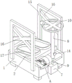
FIG. 1 is a schematic view of the overall structure of the present invention;
FIG. 2 is a cross-sectional view of FIG. 1;
FIG. 3 is a front cross-sectional view of FIG. 2;
fig. 4 is an enlarged view at a in fig. 1.
In the figure: 1. a box body; 2. placing the plate; 3. a threaded rod; 4. a rectangular block; 5. a first fixing plate; 6. a support plate; 7. a housing; 8. a vertical rod; 9. a vertical rod; 10. a turntable; 11. A second fixing plate; 12. a first bevel gear; 13. a second bevel gear; 14. a bolt; 15. a protection plate; 16. a stabilizing plate; 17. a limit ring.
Detailed Description
The preferred embodiments of the present invention will be described in conjunction with the accompanying drawings, and it will be understood that they are described herein for the purpose of illustration and explanation and not limitation.
Example (b): as shown in fig. 1-4, a foot drop rehabilitation assisting device comprises a box body 1, wherein the top of the box body 1 is provided with an opening, a placing plate 2 is movably connected between the front inner wall and the rear inner wall of the box body 1, and the placing plate 2 is arranged in an L shape;
the left side and the right side of the box body 1 are movably connected with a threaded rod 3 through bearings, the side wall of the threaded rod 3 is sleeved with a rectangular block 4, the top of the rectangular block 4 is fixedly connected with a first fixing plate 5, the front wall of the first fixing plate 5 is movably connected with a supporting plate 6, the rear side wall of the supporting plate 6 is movably connected with a second fixing plate 11 close to the top, the top of the second fixing plate 11 is fixedly connected with a placing plate 2, the right side wall of the box body 1 is fixedly connected with a shell 7, the right end of the threaded rod 3 penetrates through the inner ring of the bearing and extends into the shell 7 to be fixedly connected with a first bevel gear 12, a vertical pipe 8 is arranged above the shell 7, a vertical rod 9 is arranged in the vertical pipe 8, the bottom end of the vertical rod 9 penetrates through the shell 7 and is movably connected with the shell 7, the bottom end of the vertical rod 9 is fixedly connected with a second bevel gear 13, the second bevel gear 13 is meshed with the first bevel gear 12, and the top of the vertical pipe 8 is fixedly connected with a rotary table 10, the right side wall of standpipe 8 is equipped with the screw hole near bottom department, and threaded hole installs bolt 14, and bolt 14 left end extends to and contacts with montant 9 in the standpipe 8.
In this embodiment, through setting up box 1, placing board 2, threaded rod 3, rectangular block 4, standpipe 8, montant 9 etc. drive threaded rod 3 through rotating montant 9 and rotate when in-service use, make the inclination of placing board 2 obtain adjusting as required, reach the patient and can adjust the inclination of placing board 2 on placing board 2, can effectively reach its convenient use.
Wherein, the first slider of 4 bottom fixedly connected with of rectangle pieces, 1 inner chamber bottom of box seted up with first slider assorted first spout.
Wherein, the front and back lateral walls of the box body 1 are respectively fixedly connected with a protection plate 15, and a stabilizing plate 16 is fixedly connected between the left and right inner walls of the protection plate 15.
Wherein, the left and right sides of the vertical rod 9 are respectively fixedly connected with a second sliding block, and the left and right inner walls of the vertical pipe 8 are respectively provided with a second sliding chute matched with the second sliding block.
Wherein, place two spacing rings 17 of 2 top fixedly connected with of board, place 2 tops of board and lie in spacing ring 17 internal fixation and be connected with slipmat.
In this embodiment, through setting up standpipe 8, montant 9, bolt 14, guard plate 15 etc. when the in-service use, can adjust the height of carousel 10 through bolt 14, reach and to adjust according to the patient of different physiques to can effectual improvement its application range.
Wherein, the bottom of the box body 1 is fixedly connected with a bottom plate near four corners respectively.
The working principle is as follows: when the device is used, a patient can stand in the two limiting rings 17 on the placing plate 2 and hold the turntable 10 by hand, so that the safety of the patient is ensured, the patient can adjust the inclination of the placing plate 2 according to the requirement, the vertical pipe 8 and the vertical rod 9 are driven to rotate by rotating the rotary table 10, the vertical rod 9 drives the threaded rod 3 to rotate by the second bevel gear 13 and the first bevel gear 12 synchronously, the rectangular block 4 and the first fixing plate 5 are driven to move leftwards or rightwards by the threaded rod 3, the placing plate 2 is pushed to turn leftwards or rightwards by the first fixing plate 5 through the supporting plate 6, and the purpose of adjusting the inclination angle of the placing plate 2 is achieved, if the height of carousel 1 needs to be adjusted, upwards pull or push down carousel 1 and standpipe 8 after unscrewing bolt 14, screw up bolt 14 again after the adjustment is accomplished, with the rigidity of standpipe 8 and carousel 10, reach and to carry out height-adjusting's purpose according to the patient of different physiques.
Finally, it should be noted that: in the description of the present invention, it should be noted that the terms "vertical", "upper", "lower", "horizontal", and the like indicate orientations or positional relationships based on those shown in the drawings, and are only for convenience of describing the present invention and simplifying the description, but do not indicate or imply that the referred device or element must have a specific orientation, be constructed in a specific orientation, and be operated, and thus, should not be construed as limiting the present invention.
In the description of the present invention, it should also be noted that, unless otherwise explicitly specified or limited, the terms "disposed," "mounted," "connected," and "connected" are to be construed broadly and may, for example, be fixedly connected, detachably connected, or integrally connected; can be mechanically or electrically connected; they may be connected directly or indirectly through intervening media, or they may be interconnected between two elements. The specific meanings of the above terms in the present invention can be understood by those skilled in the art according to specific situations.
Although the present invention has been described in detail with reference to the foregoing embodiments, it will be apparent to those skilled in the art that changes may be made in the embodiments and/or equivalents thereof without departing from the spirit and scope of the utility model. Any modification, equivalent replacement, or improvement made within the spirit and principle of the present invention should be included in the protection scope of the present invention.
Claims (6)
1. The foot drop rehabilitation assisting device comprises a box body (1), and is characterized in that the top of the box body (1) is provided with an opening, a placing plate (2) is movably connected between the front inner wall and the rear inner wall of the box body (1), and the placing plate (2) is arranged in an L shape;
the box body (1) is provided with a threaded rod (3) at the left side and the right side through a bearing, the threaded rod (3) is sleeved with a rectangular block (4) on the side wall, the top of the rectangular block (4) is fixedly connected with a first fixing plate (5), the front wall of the first fixing plate (5) is movably connected with a supporting plate (6), the back side wall of the supporting plate (6) is close to the top and is movably connected with a second fixing plate (11), the top of the second fixing plate (11) is fixedly connected with a placing plate (2), the right side wall of the box body (1) is fixedly connected with a shell (7), the right end of the threaded rod (3) penetrates through an inner bearing ring and extends into the shell (7) to be fixedly connected with a first bevel gear (12), a vertical pipe (8) is arranged above the shell (7), a vertical rod (9) is arranged in the vertical pipe (8), the bottom end of the vertical rod (9) penetrates through the shell (7) and is movably connected with the shell (7), montant (9) bottom fixedly connected with second bevel gear (13), second bevel gear (13) mesh mutually with first bevel gear (12), standpipe (8) top fixedly connected with carousel (10), standpipe (8) right side wall is close to bottom department set up threaded hole, threaded hole installs bolt (14), bolt (14) left end contacts with montant (9) in extending to standpipe (8).
2. The foot drop rehabilitation assisting device as claimed in claim 1, wherein a first sliding block is fixedly connected to the bottom of the rectangular block (4), and a first sliding groove matched with the first sliding block is formed in the bottom of an inner cavity of the box body (1).
3. The foot drop rehabilitation assisting device as claimed in claim 1, wherein the front and rear side walls of the box body (1) are fixedly connected with protection plates (15) respectively, and stabilizing plates (16) are fixedly connected between the left and right inner walls of the protection plates (15).
4. The foot drop rehabilitation assisting device as claimed in claim 1, wherein the left side and the right side of the vertical rod (9) are respectively and fixedly connected with a second sliding block, and the left inner wall and the right inner wall of the vertical tube (8) are respectively provided with a second sliding groove matched with the second sliding block.
5. The foot drop rehabilitation assisting device as claimed in claim 1, wherein two limiting rings (17) are fixedly connected to the top of the placing plate (2), and a non-slip mat is fixedly connected to the top of the placing plate (2) in the limiting rings (17).
6. The foot drop rehabilitation assisting device as claimed in claim 1, wherein bottom plates are fixedly connected to the bottom of the box body (1) near four corners respectively.
Priority Applications (1)
| Application Number | Priority Date | Filing Date | Title |
|---|---|---|---|
| CN202122008011.2U CN215503615U (en) | 2021-08-25 | 2021-08-25 | Foot drop rehabilitation auxiliary device |
Applications Claiming Priority (1)
| Application Number | Priority Date | Filing Date | Title |
|---|---|---|---|
| CN202122008011.2U CN215503615U (en) | 2021-08-25 | 2021-08-25 | Foot drop rehabilitation auxiliary device |
Publications (1)
| Publication Number | Publication Date |
|---|---|
| CN215503615U true CN215503615U (en) | 2022-01-14 |
Family
ID=79793201
Family Applications (1)
| Application Number | Title | Priority Date | Filing Date |
|---|---|---|---|
| CN202122008011.2U Expired - Fee Related CN215503615U (en) | 2021-08-25 | 2021-08-25 | Foot drop rehabilitation auxiliary device |
Country Status (1)
| Country | Link |
|---|---|
| CN (1) | CN215503615U (en) |
-
2021
- 2021-08-25 CN CN202122008011.2U patent/CN215503615U/en not_active Expired - Fee Related
Similar Documents
| Publication | Publication Date | Title |
|---|---|---|
| CN216496188U (en) | Anti-sliding inflation device | |
| CN208756386U (en) | The limb support frame of calf lifting angle is adjusted in a kind of obstetrics and gynecology department | |
| CN210843926U (en) | Hospital bed accompanying type surgical nursing support | |
| CN219921873U (en) | Leg limiter for pelvic tumor radiotherapy | |
| CN111759656A (en) | Novel orthopedics treatment is with supplementary device | |
| CN208974459U (en) | Medical electric diagnostic bed | |
| CN210330749U (en) | Bed Mounted Surgical Instrument Tray | |
| CN208838472U (en) | A knee-chest lying position auxiliary support | |
| CN211834751U (en) | Adjustable traction support of shank for medical orthopedics | |
| CN211354511U (en) | Novel medical medicine cabinet with adjustable height | |
| CN108150804A (en) | A kind of stand-type office bracket for computer | |
| CN210408838U (en) | Prone position turning-over bed | |
| CN216394605U (en) | Novel multi-functional upper limbs operation is supplementary device | |
| CN222738309U (en) | A mobile bladder flushing stand | |
| CN215385441U (en) | Strutting arrangement is used in uropoiesis surgery nursing | |
| CN211875586U (en) | Fixing base for orthopedic equipment | |
| CN215350218U (en) | Dressing frame for orthopedic rehabilitation | |
| CN222265631U (en) | Medical nursing bracket | |
| CN222195378U (en) | Adjustable's frame of changing dressings | |
| CN214908056U (en) | Auxiliary vehicle for operating room nursing | |
| CN221980901U (en) | Adjustable lifting structure of OCT mandibular support | |
| CN213465692U (en) | Medical multifunctional nursing bed convenient to adjust | |
| CN221451048U (en) | Adjustable auxiliary support for spinal surgery | |
| CN217245320U (en) | Tray placing frame | |
| CN214713334U (en) | Internal medicine outpatient service chair |
Legal Events
| Date | Code | Title | Description |
|---|---|---|---|
| GR01 | Patent grant | ||
| GR01 | Patent grant | ||
| CF01 | Termination of patent right due to non-payment of annual fee |
Granted publication date: 20220114 |
|
| CF01 | Termination of patent right due to non-payment of annual fee |