CN215498540U - A generator set with remote communication function - Google Patents

A generator set with remote communication function Download PDF

Info

Publication number
CN215498540U
CN215498540U CN202121916139.2U CN202121916139U CN215498540U CN 215498540 U CN215498540 U CN 215498540U CN 202121916139 U CN202121916139 U CN 202121916139U CN 215498540 U CN215498540 U CN 215498540U
Authority
CN
China
Prior art keywords
generator set
photovoltaic
rain
main body
outer cover
Prior art date
Legal status (The legal status is an assumption and is not a legal conclusion. Google has not performed a legal analysis and makes no representation as to the accuracy of the status listed.)
Active
Application number
CN202121916139.2U
Other languages
Chinese (zh)
Inventor
胡岭
孙丽
胡迪
Current Assignee (The listed assignees may be inaccurate. Google has not performed a legal analysis and makes no representation or warranty as to the accuracy of the list.)
Stenico Generator Jiangsu Co ltd
Original Assignee
Shanghai Kosda Electric Co ltd
Priority date (The priority date is an assumption and is not a legal conclusion. Google has not performed a legal analysis and makes no representation as to the accuracy of the date listed.)
Filing date
Publication date
Application filed by Shanghai Kosda Electric Co ltd filed Critical Shanghai Kosda Electric Co ltd
Priority to CN202121916139.2U priority Critical patent/CN215498540U/en
Application granted granted Critical
Publication of CN215498540U publication Critical patent/CN215498540U/en
Active legal-status Critical Current
Anticipated expiration legal-status Critical

Links

Images

Classifications

    • Y—GENERAL TAGGING OF NEW TECHNOLOGICAL DEVELOPMENTS; GENERAL TAGGING OF CROSS-SECTIONAL TECHNOLOGIES SPANNING OVER SEVERAL SECTIONS OF THE IPC; TECHNICAL SUBJECTS COVERED BY FORMER USPC CROSS-REFERENCE ART COLLECTIONS [XRACs] AND DIGESTS
    • Y02—TECHNOLOGIES OR APPLICATIONS FOR MITIGATION OR ADAPTATION AGAINST CLIMATE CHANGE
    • Y02E—REDUCTION OF GREENHOUSE GAS [GHG] EMISSIONS, RELATED TO ENERGY GENERATION, TRANSMISSION OR DISTRIBUTION
    • Y02E10/00—Energy generation through renewable energy sources
    • Y02E10/50—Photovoltaic [PV] energy
    • Y02E10/56—Power conversion systems, e.g. maximum power point trackers

Landscapes

  • Selective Calling Equipment (AREA)

Abstract

本实用新型公开了一种具有远程通讯功能的发电机组,包括发电机组主体、底座、防雨外罩、光伏发电板和无线通讯天线,该具有远程通讯功能的发电机组,使用时,防雨外罩可对电机机组主体进行挡雨,光伏发电板吸热发电产生的电能通过光伏控制器一部分传输到蓄电箱保存,另一部分通过光伏逆变器转换成直流电供给其它用电设备,全景摄像头可对发电机组主体进行实时视频监控,烟雾传感器和温湿度传感器可自动监测发电机组主体周围的烟雾浓度以及温湿度状况,一旦出现烟雾浓度超标或者温湿度超出正常范围,便会在控制器控制下通过无线通讯天线发送给用户手机或者电脑终端,便于用户进行远程监控以及方便及时处理。

Figure 202121916139

The utility model discloses a generator set with remote communication function, comprising a generator set main body, a base, a rainproof cover, a photovoltaic power generation panel and a wireless communication antenna. The generator set with remote communication function, when in use, the rainproof cover can be The main body of the motor unit is protected from rain, and the electric energy generated by the photovoltaic power generation panel is transmitted to the storage box through the photovoltaic controller, and the other part is converted into direct current through the photovoltaic inverter to supply other electrical equipment. The panoramic camera can generate electricity. The main body of the unit performs real-time video monitoring. The smoke sensor and temperature and humidity sensor can automatically monitor the smoke concentration and temperature and humidity conditions around the main body of the generator set. Once the smoke concentration exceeds the standard or the temperature and humidity exceeds the normal range, it will be controlled by the controller through wireless communication. The antenna is sent to the user's mobile phone or computer terminal, which is convenient for the user to perform remote monitoring and timely processing.

Figure 202121916139

Description

Generating set with remote communication function
Technical Field
The utility model relates to the technical field of generator sets, in particular to a generator set with a remote communication function.
Background
In order to effectively solve the power supply contradiction and relieve the power supply crisis, a power department encourages power consumers to configure generators by themselves, and timely power supply service is provided for users by utilizing the self-generating function of the generators, most users purchase the generator sets and place the generator sets indoors, and the generator sets are provided with independent generator set rooms, but the generator sets need to be placed outdoors at use places such as construction sites, mines, petroleum and the like.
However, the existing generator set has the following disadvantages;
1. the existing generator set does not have a remote communication function, so that a user cannot carry out remote safety monitoring on the generator set placed outdoors, and the use safety is not high.
2. The existing generator set is poor in rainproof effect, equipment is easily damaged due to rain, and the service life is short.
SUMMERY OF THE UTILITY MODEL
The utility model aims to provide a generator set with a remote communication function so as to solve the problems in the background technology.
In order to achieve the purpose, the utility model provides the following technical scheme:
the utility model provides a generating set with remote communication function, includes generating set main part, base, rain-proof dustcoat, photovoltaic power generation board and wireless communication antenna, the base is installed to the bottom of generating set main part, the outside of generating set main part is provided with rain-proof dustcoat, photovoltaic power generation board is installed at the top of rain-proof dustcoat, wireless communication antenna is installed at one side of photovoltaic power generation board at the top of rain-proof dustcoat, panoramic camera is installed to the interior top surface of rain-proof dustcoat, smoke transducer is installed to one side of panoramic camera, temperature and humidity sensor is installed to panoramic camera's opposite side, the equipment fixing chamber has been seted up in the generating set main part, total controller, photovoltaic inverter, accumulator case and photovoltaic controller are installed to the equipment fixing intracavity.
As a further scheme of the utility model: the front end of the rainproof outer cover is provided with a front baffle, the upper end of the front baffle is provided with a hinge, and the front baffle is movably hinged with the rainproof outer cover through the hinge.
As a still further scheme of the utility model: the rain-proof dustcoat is characterized in that telescopic support rods are arranged between the two sides of the front baffle and the rain-proof dustcoat, and the two ends of each telescopic support rod are movably hinged with the front baffle and the rain-proof dustcoat respectively.
As a still further scheme of the utility model: the outer walls of the two sides of the rainproof outer cover are provided with shutters, and the front baffle is provided with a transparent glass window.
As a still further scheme of the utility model: the photovoltaic power generation board passes through wire and photovoltaic controller electric connection, the photovoltaic controller passes through the wire respectively with accumulator case and photovoltaic inverter electric connection, photovoltaic inverter passes through wire and total controller electric connection.
As a still further scheme of the utility model: the smoke sensor, the temperature and humidity sensor and the panoramic camera are all electrically connected with the master controller through leads, the master controller is electrically connected with the wireless communication antenna through leads, and the wireless communication antenna is wirelessly connected with a mobile phone terminal or a computer end through a communication base station.
Compared with the prior art, the utility model has the beneficial effects that:
1. according to the utility model, by arranging the camera, the smoke sensor, the temperature and humidity sensor and the wireless communication antenna, the camera can carry out video monitoring on the generator set main body in real time, the smoke sensor and the temperature and humidity sensor can automatically monitor the smoke concentration and the temperature and humidity state around the generator set main body, and once the situation that large smoke exists around the generator set main body or the temperature and humidity exceed the safe use range is found, the smoke is transmitted to a user mobile phone or a computer terminal through the wireless communication antenna, so that the user can timely process the smoke and the humidity, and the smoke and the temperature are conveniently monitored
2. According to the utility model, the rain-proof outer cover is arranged, the rain-proof outer cover can shield rain for the generator set main body, the safety of outdoor use is improved, meanwhile, the shutters are arranged on two sides of the rain-proof outer cover, normal heat dissipation of the generator set main body can be ensured, the front baffle can be convenient for personnel to overhaul and maintain, the photovoltaic power generation board is arranged on the rain-proof outer cover, solar power generation can be carried out, electric energy generated by power generation is supplied to each electric device in the device for use, and the effects of energy conservation and environmental protection are achieved.
Drawings
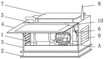
Fig. 1 is a front view of a generator set with telecommunications capabilities.
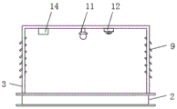
Figure 2 is a front cross-sectional view of the protective enclosure of figure 1 for a power generation unit having telecommunications capabilities.
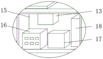
Fig. 3 is an enlarged view of a power generating unit having a telecommunication function at a in fig. 1.
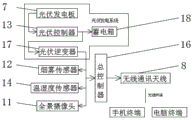
Fig. 4 is a block diagram of a structure of a generator set with a telecommunication function.
1. A generator set main body; 2. a base; 3. a rain-proof outer cover; 4. a front baffle; 5. a hinge; 6. a telescopic support rod; 7. a photovoltaic power generation panel; 8. a wireless communication antenna; 9. a blind window; 10. a transparent glass window; 11. a panoramic camera; 12. a smoke sensor; 13. a photovoltaic controller; 14. a temperature and humidity sensor; 15. an equipment installation cavity; 16. a master controller; 17. a photovoltaic inverter; 18. an accumulator box.
Detailed Description
The technical solutions in the embodiments of the present invention will be clearly and completely described below with reference to the drawings in the embodiments of the present invention, and it is obvious that the described embodiments are only a part of the embodiments of the present invention, and not all of the embodiments. All other embodiments, which can be derived by a person skilled in the art from the embodiments given herein without making any creative effort, shall fall within the protection scope of the present invention.
Referring to fig. 1-4, in the embodiment of the utility model, a generator set with a remote communication function includes a generator set main body 1, a base 2, a rainproof cover 3, a photovoltaic power generation board 7 and a wireless communication antenna 8, the base 2 is installed at the bottom of the generator set main body 1, the rainproof cover 3 is installed outside the generator set main body 1, the photovoltaic power generation board 7 is installed at the top of the rainproof cover 3, the wireless communication antenna 8 is installed at one side of the photovoltaic power generation board 7 at the top of the rainproof cover 3, a panoramic camera 11 is installed at the inner top surface of the rainproof cover 3, a smoke sensor 12 is installed at one side of the panoramic camera 11, the type of the smoke sensor 12 is JTY-GD-S836, a temperature and humidity sensor 14 is installed at the other side of the panoramic camera 11, the type of the temperature and humidity sensor 14 is SQHT03, an equipment installation cavity 15 is formed in the generator set main body 1, a master controller 16, a photovoltaic inverter 17, a storage box 18 and a photovoltaic controller 13 are installed in the equipment installation cavity 15, the model of the master controller 16 is S7-200, and the model of the photovoltaic controller 13 is GF-30I-01.
The front end of the rain-proof outer cover 3 is provided with a front baffle 4, the upper end of the front baffle 4 is provided with a hinge 5, and the front baffle 4 is movably hinged with the rain-proof outer cover 3 through the hinge 5.
Install flexible bracing piece 6 between the both sides of preceding baffle 4 and rain-proof dustcoat 3, the both ends of flexible bracing piece 6 are articulated with preceding baffle 4 and rain-proof dustcoat 3 activity respectively, are provided with the fastener on the flexible bracing piece 6, are convenient for adjust the length of flexible bracing piece 6.
Install shutter 9 on the both sides outer wall of rain-proof dustcoat 3, shutter 9 has stronger waterproof performance when can playing the radiating, installs clear glass window 10 on the preceding baffle 4, and clear glass window 10 makes things convenient for personnel to stand the running state at rain-proof dustcoat 3 outside direct observation generating set main part 1.
The photovoltaic power generation board 7 is electrically connected with the photovoltaic controller 13 through a lead, the photovoltaic controller 13 is electrically connected with the storage battery box 18 and the photovoltaic inverter 17 through leads, and the photovoltaic inverter 17 is electrically connected with the master controller 16 through a lead.
The smoke sensor 12, the temperature and humidity sensor 14 and the panoramic camera 11 are electrically connected with a master controller 16 through leads, the master controller 16 is electrically connected with the wireless communication antenna 8 through leads, and the wireless communication antenna 8 is wirelessly connected with a mobile phone terminal or a computer end through a communication base station.
The working principle of the utility model is as follows:
during the use, rain-proof dustcoat 3 can keep off the rain to generating set main part 1, photovoltaic power generation board 7 absorbs heat and generates electricity the electric energy and transmit to accumulator case 18 through photovoltaic controller 13 and preserve, another part converts the direct current into through photovoltaic inverter 17 and supplies with other consumer, panoramic camera 11 can carry out real-time video monitoring to generating set main part 1, smoke transducer 12 and temperature and humidity sensor 14 can automatic monitoring generating set main part 1 around smog concentration and humiture situation, in case smog concentration exceeds standard or humiture exceedes normal range, just can send for user's cell-phone or computer terminal through wireless communication antenna 8 under the control of master controller 16, be convenient for the user to carry out remote monitoring and convenient in time handle.
Although the present invention has been described in detail with reference to the foregoing embodiments, it will be apparent to those skilled in the art that various changes in the embodiments and/or modifications of the utility model can be made, and equivalents and modifications of some features of the utility model can be made without departing from the spirit and scope of the utility model.

Claims (6)

1. The utility model provides a generating set with remote communication function, includes generating set main part (1), base (2), rain-proof dustcoat (3), photovoltaic power generation board (7) and wireless communication antenna (8), its characterized in that: a base (2) is arranged at the bottom of the generator set main body (1), a rainproof outer cover (3) is arranged outside the generator set main body (1), the top of the rain-proof outer cover (3) is provided with a photovoltaic power generation board (7), the top of the rain-proof outer cover (3) is provided with a wireless communication antenna (8) at one side of the photovoltaic power generation board (7), a panoramic camera (11) is arranged on the inner top surface of the rainproof outer cover (3), a smoke sensor (12) is arranged on one side of the panoramic camera (11), a temperature and humidity sensor (14) is arranged on the other side of the panoramic camera (11), the device comprises a generator set main body (1), and is characterized in that an equipment installation cavity (15) is formed in the generator set main body (1), and a master controller (16), a photovoltaic inverter (17), an accumulator box (18) and a photovoltaic controller (13) are installed in the equipment installation cavity (15).
2. The generator set with telecommunication function of claim 1, wherein: the front end of the rainproof outer cover (3) is provided with a front baffle (4), a hinge (5) is installed at the upper end of the front baffle (4), and the front baffle (4) is movably hinged with the rainproof outer cover (3) through the hinge (5).
3. The generator set with telecommunication function as claimed in claim 2, wherein: the rain-proof cover is characterized in that a telescopic supporting rod (6) is arranged between the two sides of the front baffle (4) and the rain-proof cover (3), and the two ends of the telescopic supporting rod (6) are movably hinged with the front baffle (4) and the rain-proof cover (3) respectively.
4. The generator set with telecommunication function as claimed in claim 2, wherein: the rainproof outer cover is characterized in that the outer walls of two sides of the rainproof outer cover (3) are provided with shutters (9), and the front baffle (4) is provided with a transparent glass window (10).
5. The generator set with telecommunication function of claim 1, wherein: the photovoltaic power generation board (7) is electrically connected with a photovoltaic controller (13) through a lead, the photovoltaic controller (13) is respectively electrically connected with a storage battery box (18) and a photovoltaic inverter (17) through leads, and the photovoltaic inverter (17) is electrically connected with a master controller (16) through leads.
6. The generator set with telecommunication function of claim 1, wherein: the smoke sensor (12), the temperature and humidity sensor (14) and the panoramic camera (11) are electrically connected with a master controller (16) through leads, the master controller (16) is electrically connected with the wireless communication antenna (8) through leads, and the wireless communication antenna (8) is wirelessly connected with a mobile phone terminal or a computer end through a communication base station.
CN202121916139.2U 2021-08-16 2021-08-16 A generator set with remote communication function Active CN215498540U (en)

Priority Applications (1)

Application Number Priority Date Filing Date Title
CN202121916139.2U CN215498540U (en) 2021-08-16 2021-08-16 A generator set with remote communication function

Applications Claiming Priority (1)

Application Number Priority Date Filing Date Title
CN202121916139.2U CN215498540U (en) 2021-08-16 2021-08-16 A generator set with remote communication function

Publications (1)

Publication Number Publication Date
CN215498540U true CN215498540U (en) 2022-01-11

Family

ID=79760112

Family Applications (1)

Application Number Title Priority Date Filing Date
CN202121916139.2U Active CN215498540U (en) 2021-08-16 2021-08-16 A generator set with remote communication function

Country Status (1)

Country Link
CN (1) CN215498540U (en)

Similar Documents

Publication Publication Date Title
JP3177767U (en) Solar power system
CN108598892A (en) A kind of outdoor power equipment with lightning arrester
CN207203262U (en) A kind of comprehensive blower fan fire-fighting system
CN207753648U (en) A kind of traffic monitoring apparatus wind-light complementing power generation device
CN207926049U (en) A kind of electric power high-voltage ring main unit
CN207320584U (en) A kind of electric power cabinet easy to remove with water-proof function
CN206948790U (en) A kind of communication engineering optical fiber commuting case
CN212969833U (en) Video monitoring equipment of 5G communication base station
CN220382791U (en) Energy storage power supply with protective structure
CN207053007U (en) A kind of electric power safety transformer station
CN215529621U (en) Energy-saving electrical cabinet with built-in wire arrangement structure
CN215500050U (en) Outdoor hidden non-standard electrical control cabinet
CN213960024U (en) Photovoltaic power station inverter evaluation device
CN215600815U (en) Block terminal for intelligent engineering of building
CN209844236U (en) Electric automatization PLC outdoor protection type equipment
CN207625344U (en) A kind of DC UPS
CN218097855U (en) Comprehensive monitoring equipment of transmission tower
CN209282921U (en) Industrial energy-saving emergency power supply
CN209233768U (en) A kind of energy conservation electrical storage type distributed new generating equipment
CN207301234U (en) A kind of website formula status of electric power on-Line Monitor Device
CN213845937U (en) Novel intelligent looped netowrk cabinet of thing networking device
CN218724350U (en) DC power supply cabinet monitoring equipment
CN211058597U (en) Intelligent smoke exhaust system
CN205319521U (en) Novel dual power supply distribution box
CN221575749U (en) Small-size power supply unit convenient to installation

Legal Events

Date Code Title Description
GR01 Patent grant
GR01 Patent grant
TR01 Transfer of patent right

Effective date of registration: 20260227

Address after: 225222 Jiangsu Province Yangzhou City Jiangdu District Wuqiao Town Industrial Park Xiewu Road 132.NO

Patentee after: Stenico Generator (Jiangsu) Co.,Ltd.

Country or region after: China

Address before: 201418 Building 1, No. 1, Haikun Road, Fengxian District, Shanghai

Patentee before: Shanghai kosda Electric Co.,Ltd.

Country or region before: China