CN215491387U - Notebook computer tool porous position degree detection device - Google Patents
Notebook computer tool porous position degree detection device Download PDFInfo
- Publication number
- CN215491387U CN215491387U CN202121237628.5U CN202121237628U CN215491387U CN 215491387 U CN215491387 U CN 215491387U CN 202121237628 U CN202121237628 U CN 202121237628U CN 215491387 U CN215491387 U CN 215491387U
- Authority
- CN
- China
- Prior art keywords
- detection
- notebook computer
- pin
- block
- main detection
- Prior art date
- Legal status (The legal status is an assumption and is not a legal conclusion. Google has not performed a legal analysis and makes no representation as to the accuracy of the status listed.)
- Expired - Fee Related
Links
Images




Landscapes
- A Measuring Device Byusing Mechanical Method (AREA)
Abstract
The utility model discloses a device for detecting the position degree of a plurality of holes of a notebook computer jig, which comprises a detection table, wherein the lower end of the detection table is fixedly provided with support legs, the detection table is provided with a base, the detection table is provided with a moving mechanism for driving the base to move, the base is fixedly provided with a positioning frame, the detection table is fixedly provided with a portal frame, the portal frame is downwards fixedly provided with a telescopic cylinder, a piston rod of the telescopic cylinder is downwards arranged and fixedly provided with a mounting plate, and the lower end of the mounting plate is distributed with detection pin assemblies. The notebook computer jig porous position degree detection device has the advantages of simple structure, high efficiency and high detection precision.
Description
Technical Field
The utility model relates to the technical field of notebook computer jigs, in particular to a device for detecting the position degree of multiple holes of a notebook computer jig.
Background
The notebook computer jig is a common jig in the production process of the notebook computer, plays a vital role in the production link, and has more holes for assembly and positioning, so that the position precision requirement of the holes is higher.
At present, the hole position degree detection modes and equipment are few, and most of the hole position degrees are detected by single holes, but most of notebook computer jigs are provided with a plurality of hole positions, so that the efficiency is low and the precision is poor when a single jig is detected.
Disclosure of Invention
To the not enough of above-mentioned prior art, the technical problem that this patent application will solve provides a simple structure, efficient, detects the high notebook computer tool porous position degree detection device of precision.
In order to solve the technical problems, the utility model adopts the following technical scheme:
the utility model provides a notebook computer tool porous position degree detection device, is including examining test table, the lower extreme fixed mounting who examines test table has the stabilizer blade, it is provided with the base on the test table to examine, examine and to install the moving mechanism who is used for driving the base and removes on the test table, fixed mounting has the locating frame on the base, it has the portal frame to examine fixed mounting on the test table, the downward fixed mounting of portal frame has telescopic cylinder, telescopic cylinder's piston rod sets up and fixed mounting has the mounting panel downwards, the lower extreme distribution of mounting panel installs the detection round pin subassembly.
The moving mechanism comprises two push-pull air cylinders fixedly mounted on the detection platform, piston rods of the push-pull air cylinders are horizontally arranged and fixedly connected with the base, and the number of the push-pull air cylinders is two.
Wherein, the detection round pin subassembly includes the main detection round pin and vice detection round pin, vice detection round pin is provided with at least 3 and the equipartition sets up the circumference at the main detection round pin, the lower extreme fixed mounting of main detection round pin has the main detection piece, the main detection piece is the minimum diameter size of inspection hole, the lower extreme fixed mounting of vice detection round pin has vice detection piece, vice detection piece is just for the straight face to the surface of main detection piece, and the outside surface of vice detection piece is the inclined plane, inclined plane leanin, vice detection piece is located the main detection piece circumference.
The structure of the main detection pin is the same as that of the auxiliary detection pin, the main detection pin comprises an outer barrel and a barrel rod in sliding fit with the outer barrel, the upper end of the outer barrel is fixedly connected with a mounting plate through a mounting disc, a stop block is fixedly mounted at the upper end of the barrel rod, a convex edge is arranged at the lower end of the outer barrel in an inward protruding mode, the stop block is abutted against the convex edge, a pressure sensor is fixedly mounted right opposite to the barrel rod through the mounting disc, a compression spring is arranged between the pressure sensor and the stop block, and the lower end of the barrel rod is fixedly connected with the main detection block or the auxiliary detection block.
Wherein, the both sides of locating frame are seted up and are stepped down the groove.
In conclusion, the device for detecting the position of the plurality of holes of the notebook computer jig has the advantages of simple structure, high efficiency and high detection precision.
Drawings
Fig. 1 is a schematic structural diagram of a device for detecting the position of a plurality of holes of a notebook computer jig according to the present invention.
FIG. 2 is an isometric view of the sensing pin assembly of FIG. 1.
FIG. 3 is a partial schematic view of the sensing pin assembly and sensing bore.
FIG. 4 is a partial schematic view of the sensing pin assembly and sensing bore.
FIG. 5 is a partial schematic view of the sensing pin assembly and sensing bore.
FIG. 6 is a partial schematic view of the sensing pin assembly and sensing bore.
Detailed Description
The present invention will be described in further detail with reference to the accompanying drawings. In the description of the present invention, it is to be understood that the orientation or positional relationship indicated by the orientation words such as "upper, lower" and "top, bottom" etc. are usually based on the orientation or positional relationship shown in the drawings, and are only for convenience of description and simplicity of description, and in the case of not making a reverse description, these orientation words do not indicate and imply that the device or element referred to must have a specific orientation or be constructed and operated in a specific orientation, and therefore, should not be interpreted as limiting the scope of the present invention; the terms "inner and outer" refer to the inner and outer relative to the profile of the respective component itself.
As shown in fig. 1-2, a notebook computer tool porous position degree detection device, including examining test table 1, the lower extreme fixed mounting who examines test table has stabilizer blade 2, it is provided with base 3 on the test table to examine, examine and install the moving mechanism who is used for driving the base and remove on the test table, fixed mounting has locating frame 4 on the base, it has portal frame 5 to examine fixed mounting on the test table, the downward fixed mounting of portal frame has telescopic cylinder 6, telescopic cylinder's piston rod sets up and fixed mounting has mounting panel 7 downwards, the lower extreme distribution of mounting panel is installed and is detected round pin subassembly 8.
Therefore, the notebook computer jig 9 to be detected is placed in the positioning frame, the moving mechanism drives the base to move to the lower side of the portal frame, the piston rod of the telescopic cylinder extends downwards to drive the mounting plate to move downwards, and the detecting pin assembly is used for detecting the detecting hole 10 in the notebook computer jig. After the detection is finished, the piston rod of the telescopic cylinder pushes the base to move outwards, the notebook computer jig after the detection is taken down by an operator, the notebook computer jig to be detected is placed in the positioning frame, and the detection is continued.
The moving mechanism comprises a push-pull air cylinder 11 fixedly installed on the detection platform, a piston rod of the push-pull air cylinder is horizontally arranged and fixedly connected with the base, and the number of the push-pull air cylinders is two. The push-pull cylinder drives the base to move.
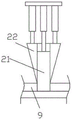
Wherein, the detection round pin subassembly includes the main detection round pin and vice detection round pin, vice detection round pin is provided with at least 3 and the equipartition sets up the circumference at the main detection round pin, the lower extreme fixed mounting of main detection round pin has main detection piece 21, the main detection piece is the minimum diameter size of inspection hole, the lower extreme fixed mounting of vice detection round pin has vice detection piece 22, vice detection piece is just for the surface of main detection piece for straight face, and the outside surface of vice detection piece is the inclined plane, inclined plane leanin, vice detection piece is located the main detection piece circumference.
In this way, the main detection pin is used for detecting the detection hole, the main detection pin is the minimum size of the detection hole, the size of the auxiliary detection pin is gradually increased from bottom to top, and the auxiliary detection pin can provide the detection of the maximum size of the detection hole.
The structure of the main detection pin is the same as that of the auxiliary detection pin, the main detection pin comprises an outer barrel 23 and a barrel rod 24 in sliding fit with the outer barrel, the upper end of the outer barrel is fixedly connected with the mounting plate through a mounting disc 25, a stop block is fixedly mounted at the upper end of the barrel rod, a convex edge is arranged at the lower end of the outer barrel in an inward protruding mode, the stop block is abutted against the convex edge, a pressure sensor is fixedly mounted right opposite to the barrel rod through the mounting disc, a compression spring is arranged between the pressure sensor and the stop block, and the lower end of the barrel rod is fixedly connected with the main detection block or the auxiliary detection block. The section of thick bamboo pole can be followed the urceolus and slided, and upward movement when the section of thick bamboo pole receives the promotion drives the dog and presses pressure sensor, resets under compression spring's effect after detecting the completion, is convenient for detect next time. In the initial state, the cylinder rod freely falls down due to gravity, the compression spring does not compress the pressure sensor, and the pressure sensor has no indication.
Wherein, the both sides of locating frame are seted up and are stepped down groove 13. The notebook computer jig after detection is convenient to take out.
Specifically, the main detection block of the detection pin assembly is the minimum diameter size of the detection hole:
as shown in fig. 3, the main detection block is inserted into the detection hole, the auxiliary detection block cannot be inserted into the detection through hole, the pressure sensor corresponding to the auxiliary detection pin detects pressure, and the pressure sensor corresponding to the main detection pin does not detect pressure, so that the detection hole is qualified;
as shown in fig. 4, the main detection block and a part of the auxiliary detection blocks cannot be inserted into the detection holes, and the rest of the auxiliary detection blocks are inserted into the detection holes, so that the pressure sensors corresponding to the main detection pins and the part of the auxiliary detection pins detect the pressure, and the pressure sensors corresponding to the rest of the auxiliary detection pins do not detect the pressure, so that the detection holes are unqualified, and the axes of the detection holes are deviated or the size of the detection holes is smaller than the normal size;
as shown in fig. 5, the main detection block and the auxiliary detection block are inserted into the detection holes, and the pressure sensors corresponding to the main detection pin and part of the auxiliary detection pins do not detect pressure, so that the detection holes are unqualified and the size of the detection holes is larger;
as shown in fig. 6, the main detection block and the auxiliary detection block are inserted into the detection hole, the pressure sensor corresponding to the main detection pin detects pressure, and the pressure indication detected by the pressure sensor corresponding to the auxiliary detection pin is in a reasonable range, so that the size of the detection hole is qualified.
Specifically, still include the PLC controller for be connected with pressure sensor, accept pressure sensor's signal and show on the display screen, whether the operating personnel of being convenient for observes the inspection hole qualified, and the PLC controller can also control the action of wherein electrical component simultaneously.
The principle is as follows:
the notebook computer jig to be detected is placed in the positioning frame, the moving mechanism drives the base to move to the position below the portal frame, the piston rod of the telescopic cylinder extends downwards to drive the mounting plate to move downwards, and the detecting pin assembly is used for detecting the detecting hole in the notebook computer jig. After the detection is finished, the piston rod of the telescopic cylinder pushes the base to move outwards, the notebook computer jig after the detection is taken down by an operator, the notebook computer jig to be detected is placed in the positioning frame, and the detection is continued.
Finally, it should be noted that: various modifications and alterations of this invention may be made by those skilled in the art without departing from the spirit and scope of this invention. Thus, it is intended that the present invention cover the modifications and variations of this invention provided they come within the scope of the appended claims and their equivalents.
Claims (5)
1. The utility model provides a notebook computer tool porous position degree detection device, its characterized in that, is including examining test table, the lower extreme fixed mounting who examines test table has the stabilizer blade, it is provided with the base on the test table to examine, examine and to install the moving mechanism who is used for driving the base and remove on the test table, fixed mounting has the locating frame on the base, it has the portal frame to examine fixed mounting on the test table, the downward fixed mounting of portal frame has telescopic cylinder, telescopic cylinder's piston rod sets up and fixed mounting has the mounting panel downwards, the lower extreme distribution of mounting panel is installed and is detected the round pin subassembly.
2. The device for detecting the multi-hole position of the notebook computer jig according to claim 1, wherein the moving mechanism comprises two push-pull air cylinders fixedly mounted on the detection table, piston rods of the push-pull air cylinders are horizontally arranged and fixedly connected with the base.
3. The device for detecting the location degree of the multiple holes of the notebook computer jig according to claim 2, wherein the detection pin assembly comprises a main detection pin and auxiliary detection pins, the auxiliary detection pins are provided with at least 3 detection pins and are uniformly distributed in the circumferential direction of the main detection pin, a main detection block is fixedly mounted at the lower end of the main detection pin, the main detection block is the minimum diameter size of the detection hole, an auxiliary detection block is fixedly mounted at the lower end of the auxiliary detection pin, the surface of the auxiliary detection block, which faces the main detection block, is a straight surface, the outer side surface of the auxiliary detection block is an inclined surface, the inclined surface is inclined inwards, and the auxiliary detection block is located in the circumferential direction of the main detection block.
4. The device for detecting the location of the plurality of holes in the notebook computer jig according to claim 3, wherein the main detection pin and the auxiliary detection pin are identical in structure, the main detection pin comprises an outer barrel and a barrel rod which is in sliding fit with the outer barrel, the upper end of the outer barrel is fixedly connected with the mounting plate through a mounting plate, a stop block is fixedly mounted at the upper end of the barrel rod, a convex edge is arranged at the lower end of the outer barrel in an inward protruding mode, the stop block is abutted against the convex edge, a pressure sensor is fixedly mounted on the barrel rod through the mounting plate, a compression spring is arranged between the pressure sensor and the stop block, and the lower end of the barrel rod is fixedly connected with the main detection block or the auxiliary detection block.
5. The apparatus of claim 1, wherein the positioning frame has two sides formed with a recess.
Priority Applications (1)
| Application Number | Priority Date | Filing Date | Title |
|---|---|---|---|
| CN202121237628.5U CN215491387U (en) | 2021-06-04 | 2021-06-04 | Notebook computer tool porous position degree detection device |
Applications Claiming Priority (1)
| Application Number | Priority Date | Filing Date | Title |
|---|---|---|---|
| CN202121237628.5U CN215491387U (en) | 2021-06-04 | 2021-06-04 | Notebook computer tool porous position degree detection device |
Publications (1)
| Publication Number | Publication Date |
|---|---|
| CN215491387U true CN215491387U (en) | 2022-01-11 |
Family
ID=79782637
Family Applications (1)
| Application Number | Title | Priority Date | Filing Date |
|---|---|---|---|
| CN202121237628.5U Expired - Fee Related CN215491387U (en) | 2021-06-04 | 2021-06-04 | Notebook computer tool porous position degree detection device |
Country Status (1)
| Country | Link |
|---|---|
| CN (1) | CN215491387U (en) |
Cited By (1)
| Publication number | Priority date | Publication date | Assignee | Title |
|---|---|---|---|---|
| CN114486241A (en) * | 2022-04-18 | 2022-05-13 | 济南弘正科技有限公司 | Detection device for motorcycle clutch |
-
2021
- 2021-06-04 CN CN202121237628.5U patent/CN215491387U/en not_active Expired - Fee Related
Cited By (2)
| Publication number | Priority date | Publication date | Assignee | Title |
|---|---|---|---|---|
| CN114486241A (en) * | 2022-04-18 | 2022-05-13 | 济南弘正科技有限公司 | Detection device for motorcycle clutch |
| CN114486241B (en) * | 2022-04-18 | 2022-06-17 | 济南弘正科技有限公司 | Detection apparatus for motorcycle clutch |
Similar Documents
| Publication | Publication Date | Title |
|---|---|---|
| CN213780299U (en) | A keyboard testing machine and testing equipment | |
| CN208805182U (en) | A wheel hub positioning and clamping device for wheel hub detection | |
| CN110849302B (en) | Connecting rod detection device | |
| CN217571660U (en) | Axial clearance repairing device for compressor rotor and pump body | |
| CN216954472U (en) | Automobile die surface flatness detection equipment | |
| CN210572603U (en) | Jig for FPC test | |
| CN216523839U (en) | Sucker flatness detection device | |
| CN216523743U (en) | Mobile phone shell size detection device | |
| CN111610105A (en) | Fluoroplastic particle testing strength high-temperature extrusion device | |
| CN116329946A (en) | Automatic oil pump assembly equipment and method and industrial control equipment | |
| CN201352108Y (en) | Press fit examining mechanism for assembly machine of deep groove ball bearing retainer | |
| CN209364056U (en) | Automatic lock swivel nut kludge | |
| CN220040561U (en) | Probe test device | |
| CN203759684U (en) | Automatic CPU (central processing unit) taking and placing machine for testing computer main board | |
| CN212460074U (en) | Mechanical type direction detection mechanism | |
| CN219996029U (en) | New energy automobile rear floor examines utensil | |
| CN218697845U (en) | Quick change structure for automobile part checking fixture | |
| CN222994294U (en) | Detection device | |
| CN223882892U (en) | Automobile front door bright strip gauge | |
| CN219977250U (en) | Product detection jig | |
| CN213022255U (en) | A PIN needle assembly and its endurance testing equipment | |
| CN220419365U (en) | Probe mechanism of automatic PCB circuit detection device | |
| CN221350073U (en) | Display backboard production detection structure | |
| CN219511502U (en) | Bearing thickness detection device for being equipped with dust cover | |
| CN219122436U (en) | Barrel hole inspection jig |
Legal Events
| Date | Code | Title | Description |
|---|---|---|---|
| GR01 | Patent grant | ||
| GR01 | Patent grant | ||
| CF01 | Termination of patent right due to non-payment of annual fee | ||
| CF01 | Termination of patent right due to non-payment of annual fee |
Granted publication date: 20220111 |