CN215470849U - Jig for assembling radiating fin - Google Patents
Jig for assembling radiating fin Download PDFInfo
- Publication number
- CN215470849U CN215470849U CN202120962446.8U CN202120962446U CN215470849U CN 215470849 U CN215470849 U CN 215470849U CN 202120962446 U CN202120962446 U CN 202120962446U CN 215470849 U CN215470849 U CN 215470849U
- Authority
- CN
- China
- Prior art keywords
- plate
- fixedly connected
- slide rail
- chassis
- jig
- Prior art date
- Legal status (The legal status is an assumption and is not a legal conclusion. Google has not performed a legal analysis and makes no representation as to the accuracy of the status listed.)
- Expired - Fee Related
Links
- 238000003825 pressing Methods 0.000 claims abstract description 16
- 238000009434 installation Methods 0.000 abstract description 7
- XOMKZKJEJBZBJJ-UHFFFAOYSA-N 1,2-dichloro-3-phenylbenzene Chemical compound ClC1=CC=CC(C=2C=CC=CC=2)=C1Cl XOMKZKJEJBZBJJ-UHFFFAOYSA-N 0.000 description 8
- 230000009286 beneficial effect Effects 0.000 description 1
- 238000006073 displacement reaction Methods 0.000 description 1
- 238000009826 distribution Methods 0.000 description 1
- 230000000694 effects Effects 0.000 description 1
- 238000004519 manufacturing process Methods 0.000 description 1
- 239000002994 raw material Substances 0.000 description 1
Images


Landscapes
- Cooling Or The Like Of Electrical Apparatus (AREA)
Abstract
The utility model discloses an assembled radiating fin jig which comprises a bottom plate, a bearing tray, a PCB (printed circuit board), a limiting block and a connecting plate, wherein both sides of the surface of the bottom plate are fixedly connected with chassis slide rails, the upper part of the bearing tray is connected with the limiting plate through a fixing bolt in a threaded manner, one side of the bottom plate is fixedly connected with the connecting plate, one side of the connecting plate is fixedly connected with a movable slide rail, a movable slide block is sleeved on the surface of the movable slide rail in a limiting manner, one side of the movable slide block is fixedly connected with one side of a pressing plate, and a hexagonal limiting bolt is arranged on the surface of the connecting plate above the movable slide rail. The utility model not only accelerates the installation speed of the assembled radiating fin jig when in use, realizes the function of limiting and guiding when in use, but also realizes the function of conveniently assembling the radiating fin when in use.
Description
Technical Field
The utility model relates to the technical field of radiating fin assembly, in particular to a radiating fin assembly jig.
Background
With the continuous development of society, the living standard of people is also increasing, wherein the radiating fin can prolong the service life of a plurality of elements due to good radiating effect, so that people can widely use the radiating fin, and the radiating fin needs to be assembled when in use, so that a corresponding radiating fin assembling jig is needed.
This type of equipment fin tool on the market is various today, can satisfy people's user demand basically, but still has certain problem:
1. when the jig for assembling the radiating fin is used, certain trouble is caused when the jig is used due to the slow installation speed;
2. when the jig for assembling the radiating fins is used, the jig is inconvenient to limit and guide, so that the jig can have the possibility of installation deviation when being used;
3. when the jig for assembling the radiating fin is used, the radiating fin is inconvenient to install due to the inconvenience of the jig for assembling the radiating fin.
SUMMERY OF THE UTILITY MODEL
The utility model aims to provide a jig for assembling a radiating fin, which solves the problems that the jig in the background art is low in installation speed, inconvenient in limiting and guiding and inconvenient in installing the radiating fin.
In order to achieve the purpose, the utility model provides the following technical scheme: equipment fin tool, including the bottom plate, bear tray, PCB board, stopper and connecting plate, the equal fixedly connected with chassis slide rail in both sides on bottom plate surface, the top of bearing the tray has the limiting plate through fixing bolt threaded connection, one side fixedly connected with connecting plate of bottom plate, and one side fixedly connected with of connecting plate removes the slide rail, the removal slider has been cup jointed to the surface spacing of removal slide rail, one side of removal slider and one side fixed connection of clamp plate, the connecting plate surface of removal slide rail top is provided with the spacing bolt of hexagonal, the corner position department of bottom plate one side all fixedly connected with support the pad foot.
Preferably, the surface of the chassis slide rail is sleeved with a chassis slide block in a limiting manner, a bearing tray is arranged on one side of the chassis slide block, and one side of the bearing tray is fixedly connected with the surface of the chassis slide block.
Preferably, the chassis slide rail is connected with the chassis slide block in a sliding manner, and the movable slide block is connected with the movable slide rail in a sliding manner.
Preferably, a PCB is arranged on the surface of the bearing tray above the chassis sliding block, a radiating fin body is arranged above the PCB, and the top end of the radiating fin body is fixedly connected with the surface of the bottom plate through a limiting block.
Preferably, the surface of the connecting plate is provided with two hexagonal limiting bolts, and the two connecting plates are symmetrically distributed on the longitudinal central axis of the movable slide rail.
Preferably, one side of the limiting plate is fixedly connected with a pressing plate through a pressing column, and one side of the pressing plate is provided with a quick clamp.
Compared with the prior art, the utility model has the beneficial effects that: the assembled radiating fin jig not only accelerates the installation speed of the assembled radiating fin jig when in use, realizes the function of limiting and guiding when in use, but also realizes the function of conveniently assembling the radiating fin when in use;
(1) through the arrangement of the quick clamp and the pressing plate, manual force is reduced, the assembly yield of the radiating fin body 7 can be guaranteed, the mounting speed of the assembled radiating fin jig during use is increased, and therefore the practicability of the assembled radiating fin jig during use is improved;
(2) the bearing tray, the bottom plate, the chassis slide rail and the movable slide rail are arranged, the chassis slide rail and the chassis slide block on the surface of the bottom plate can limit the movement of the bearing tray when the bearing tray is pulled so as to avoid the phenomenon of installation deviation of the radiating fin body when the bearing tray is installed, the movable slide block and the movable slide rail also have the function of limiting the sliding of the pressing plate, and the movable slide rail also limits the moving range of the movable slide rail, so that the function of limiting and guiding when the assembled radiating fin jig is used is realized, and the possibility of deviation when the assembled radiating fin jig is used is avoided;
(3) through being provided with and bearing tray, PCB board and quick clamp, the operator will bear the tray and pull out, puts the PCB board on bearing the tray, fixes the PCB board, inserts appointed position department on the PCB board with the fin body, presses down the quick clamp, has realized the function that conveniently assembles the fin when this equipment fin tool uses to the convenient degree when having improved this equipment fin tool and using.
Drawings
FIG. 1 is a schematic front view of the present invention;
FIG. 2 is a schematic side view of the present invention;
FIG. 3 is a schematic bottom view of the present invention;
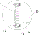
fig. 4 is an enlarged partial sectional view of a portion a in fig. 2 according to the present invention.
In the figure: 1. a base plate; 2. a carrying tray; 3. a chassis slide rail; 4. a chassis slider; 5. a PCB board; 6. a limiting block; 7. a heat sink body; 8. supporting the foot pad; 9. a connecting plate; 901. pressing a plate; 10. a hexagonal limit bolt; 11. moving the slide block; 12. moving the slide rail; 13. quickly clamping; 14. fixing the bolt; 15. a limiting plate; 16. and (5) pressing the column.
Detailed Description
The technical solutions in the embodiments of the present invention will be clearly and completely described below with reference to the drawings in the embodiments of the present invention, and it is obvious that the described embodiments are only a part of the embodiments of the present invention, and not all of the embodiments. All other embodiments, which can be derived by a person skilled in the art from the embodiments given herein without making any creative effort, shall fall within the protection scope of the present invention.
Referring to fig. 1-4, an embodiment of the present invention is shown: the assembly radiating fin jig comprises a bottom plate 1, a bearing tray 2, a PCB 5, a limiting block 6 and a connecting plate 9, wherein both sides of the surface of the bottom plate 1 are fixedly connected with chassis slide rails 3, the chassis slide rails 3 are in sliding connection with chassis slide blocks 4, and the movable slide blocks 11 are in sliding connection with movable slide rails 12, so that the bearing tray 2 can be conveniently pulled;
the surface of the chassis sliding rail 3 is sleeved with a chassis sliding block 4 in a limiting manner, one side of the chassis sliding block 4 is provided with a bearing tray 2, one side of the bearing tray 2 is fixedly connected with the surface of the chassis sliding block 4, the surface of the bearing tray 2 above the chassis sliding block 4 is provided with a PCB (printed circuit board) 5, a radiating fin body 7 is arranged above the PCB 5, and the top end of the radiating fin body 7 is fixedly connected with the surface of the bottom plate 1 through a limiting block 6, so that the PCB 5 is convenient to limit;
a limiting plate 15 is connected above the bearing tray 2 through a fixing bolt 14 in a threaded manner, a pressing plate 901 is fixedly connected to one side of the limiting plate 15 through a pressing column 16, and a quick clamp 13 is arranged on one side of the pressing plate 901, so that the PCB 5 can be conveniently installed;
one side of the bottom plate 1 is fixedly connected with a connecting plate 9, one side of the connecting plate 9 is fixedly connected with a movable slide rail 12, a movable slide block 11 is sleeved on the surface of the movable slide rail 12 in a limiting mode, one side of the movable slide block 11 is fixedly connected with one side of the pressing plate 901, and a hexagonal limiting bolt 10 is arranged on the surface of the connecting plate 9 above the movable slide rail 12;
the surface of connecting plate 9 of hexagonal spacing bolt 10 is provided with two, and two connecting plates 9 are the symmetric distribution on the vertical axis of movable slide rail 12, are convenient for inject the displacement of clamp plate 901, and the corner position department of bottom plate 1 one side all fixedly connected with supports pad foot 8.
The working principle is as follows: when the assembled radiating fin jig is used, firstly, an operator pulls out the bearing tray 2, puts the PCB 5 on the bearing tray 2, fixes the PCB 5, inserts the radiating fin body 7 at a specified position on the PCB 5, presses down the quick clamp 13 to quickly press the radiating fin body 7 on the PCB 5, greatly accelerates the installation speed of the radiating fin body 7, reduces the manual force, can ensure the assembly yield of the radiating fin body 7, greatly improves the product quality and the working efficiency, saves the energy and the raw material consumption, improves the labor condition, improves the production process and the management system, and accelerates the revolution of the industrial structure of the society and the progress of social informatization;
secondly, when the bearing tray 2 is pulled, the chassis slide rail 3 and the chassis slide block 4 on the surface of the bottom plate 1 can move and limit the bearing tray so as to avoid the phenomenon that the radiating fin body 7 is installed and deviated when the bearing tray is installed, meanwhile, the movable slide block 11 and the movable slide rail 12 have the same function of limiting and sliding the pressing plate 901, meanwhile, the movable slide rail 12 also limits the moving range of the movable slide rail, and finally, the work of assembling the radiating fin jig is completed.
It will be evident to those skilled in the art that the utility model is not limited to the details of the foregoing illustrative embodiments, and that the present invention may be embodied in other specific forms without departing from the spirit or essential attributes thereof. The present embodiments are therefore to be considered in all respects as illustrative and not restrictive, the scope of the utility model being indicated by the appended claims rather than by the foregoing description, and all changes which come within the meaning and range of equivalency of the claims are therefore intended to be embraced therein. Any reference sign in a claim should not be construed as limiting the claim concerned.
Claims (6)
1. Equipment fin tool includes bottom plate (1), bears tray (2), PCB board (5), stopper (6) and connecting plate (9), its characterized in that: bottom plate (1) both sides on surface all fixedly connected with chassis slide rail (3), there is limiting plate (15) top of bearing tray (2) through fixing bolt (14) threaded connection, one side fixedly connected with connecting plate (9) of bottom plate (1), and one side fixedly connected with of connecting plate (9) removes slide rail (12), the surperficial spacing mobile sliding block (11) of having cup jointed of removal slide rail (12), one side of removing slide block (11) and one side fixed connection of clamp plate (901), connecting plate (9) surface of removing slide rail (12) top is provided with hexagonal spacing bolt (10), the corner position department of bottom plate (1) one side all fixedly connected with supports and fills up foot (8).
2. The assembled heat sink jig of claim 1, wherein: the surface of the chassis sliding rail (3) is sleeved with a chassis sliding block (4) in a limiting mode, a bearing tray (2) is arranged on one side of the chassis sliding block (4), and one side of the bearing tray (2) is fixedly connected with the surface of the chassis sliding block (4).
3. The assembled heat sink jig of claim 1, wherein: the chassis slide rail (3) is in sliding connection with the chassis slide block (4), and the movable slide block (11) is in sliding connection with the movable slide rail (12).
4. The assembled heat sink jig of claim 2, wherein: the surface of the bearing tray (2) above the chassis sliding block (4) is provided with a PCB (printed circuit board) plate (5), a radiating fin body (7) is arranged above the PCB plate (5), and the top end of the radiating fin body (7) is fixedly connected with the surface of the bottom plate (1) through a limiting block (6).
5. The assembled heat sink jig of claim 1, wherein: the two hexagonal limiting bolts (10) are arranged on the surface of the connecting plate (9), and the two connecting plates (9) are symmetrically distributed on the longitudinal central axis of the movable slide rail (12).
6. The assembled heat sink jig of claim 1, wherein: one side of the limiting plate (15) is fixedly connected with a pressing plate (901) through a pressing column (16), and one side of the pressing plate (901) is provided with a quick clamp (13).
Priority Applications (1)
| Application Number | Priority Date | Filing Date | Title |
|---|---|---|---|
| CN202120962446.8U CN215470849U (en) | 2021-05-08 | 2021-05-08 | Jig for assembling radiating fin |
Applications Claiming Priority (1)
| Application Number | Priority Date | Filing Date | Title |
|---|---|---|---|
| CN202120962446.8U CN215470849U (en) | 2021-05-08 | 2021-05-08 | Jig for assembling radiating fin |
Publications (1)
| Publication Number | Publication Date |
|---|---|
| CN215470849U true CN215470849U (en) | 2022-01-11 |
Family
ID=79777187
Family Applications (1)
| Application Number | Title | Priority Date | Filing Date |
|---|---|---|---|
| CN202120962446.8U Expired - Fee Related CN215470849U (en) | 2021-05-08 | 2021-05-08 | Jig for assembling radiating fin |
Country Status (1)
| Country | Link |
|---|---|
| CN (1) | CN215470849U (en) |
-
2021
- 2021-05-08 CN CN202120962446.8U patent/CN215470849U/en not_active Expired - Fee Related
Similar Documents
| Publication | Publication Date | Title |
|---|---|---|
| CN219131255U (en) | Welding positioning tool for pole lugs of flexible square shell power battery module | |
| CN216869294U (en) | Quick plate sheet suspension device for plate heat exchanger | |
| CN207239200U (en) | One kind production aluminium frame Wood-plastic formwork punching aluminum profile device | |
| CN211361168U (en) | Welding fixture for intelligent terminal mainboard | |
| CN210156216U (en) | Transformer convenient for moving installation position | |
| CN220902162U (en) | Public welding frock of friction welding bottom plate front and back | |
| CN210172373U (en) | Heat-conducting plate stamping device of heat dissipation module | |
| CN213052310U (en) | Punching device for machining metal cabinet | |
| CN215470618U (en) | Assembling shielding cover jig | |
| CN214767980U (en) | Metal stamping workpiece surface leveling device | |
| CN214517723U (en) | Bridge processing and drilling device | |
| CN210209549U (en) | Positioning fixture for processing bridge support | |
| CN211917823U (en) | Press convenient to fixed work piece | |
| CN211637897U (en) | Punching machine is used in automobile parts processing | |
| CN220880100U (en) | New energy automobile safety component bumper crossbeam punching press frock | |
| CN211469927U (en) | Carrier is used in PCBA production and processing | |
| CN222674575U (en) | Soft and hard combined plate with anticreep function | |
| CN221010411U (en) | High-current field effect transistor | |
| CN217253506U (en) | Clamp for chip electro-copper | |
| CN213426581U (en) | Positioning die of circuit board | |
| CN220739289U (en) | Support frame of punch press | |
| CN216031351U (en) | Double faced adhesive tape cushion punch press template | |
| CN215453440U (en) | Quick compression fittings of HDI circuit board | |
| CN222096786U (en) | C type rubber injection molding machine | |
| CN209738263U (en) | A press for producing braking clearance automatic adjustment arm |
Legal Events
| Date | Code | Title | Description |
|---|---|---|---|
| GR01 | Patent grant | ||
| GR01 | Patent grant | ||
| CF01 | Termination of patent right due to non-payment of annual fee |
Granted publication date: 20220111 |
|
| CF01 | Termination of patent right due to non-payment of annual fee |