CN215465982U - Strong vibrating screen - Google Patents
Strong vibrating screen Download PDFInfo
- Publication number
- CN215465982U CN215465982U CN202121884022.0U CN202121884022U CN215465982U CN 215465982 U CN215465982 U CN 215465982U CN 202121884022 U CN202121884022 U CN 202121884022U CN 215465982 U CN215465982 U CN 215465982U
- Authority
- CN
- China
- Prior art keywords
- powerful
- screen
- vibration motor
- electric cabinet
- vibrating screen
- Prior art date
- Legal status (The legal status is an assumption and is not a legal conclusion. Google has not performed a legal analysis and makes no representation as to the accuracy of the status listed.)
- Expired - Fee Related
Links
- 230000000694 effects Effects 0.000 claims description 11
- 230000005540 biological transmission Effects 0.000 claims description 3
- 239000004744 fabric Substances 0.000 claims 2
- 239000000463 material Substances 0.000 description 40
- 238000012216 screening Methods 0.000 description 19
- 238000000034 method Methods 0.000 description 8
- 230000005484 gravity Effects 0.000 description 4
- 239000002699 waste material Substances 0.000 description 3
- 229910000838 Al alloy Inorganic materials 0.000 description 2
- 230000005611 electricity Effects 0.000 description 2
- 239000000956 alloy Substances 0.000 description 1
- 230000009286 beneficial effect Effects 0.000 description 1
- 230000002301 combined effect Effects 0.000 description 1
- 230000007547 defect Effects 0.000 description 1
- 238000010586 diagram Methods 0.000 description 1
- 230000005284 excitation Effects 0.000 description 1
- 238000012423 maintenance Methods 0.000 description 1
- 230000001105 regulatory effect Effects 0.000 description 1
Images



Landscapes
- Combined Means For Separation Of Solids (AREA)
- Apparatuses For Generation Of Mechanical Vibrations (AREA)
Abstract
The utility model discloses a powerful vibrating screen which comprises a fixed support, a powerful vibrating motor, a vibrating screen, a feeding hole, an electric cabinet and a collecting bin, wherein the powerful vibrating motor is arranged on the fixed support, the powerful vibration motor is welded with the fixed bracket, the vibration sieve is fixedly connected with the collection bin, a rotating shaft is arranged on the side surface of the powerful vibration motor and is rotationally connected with the powerful vibration motor, a rotating rod is arranged between the vibrating screen and the collecting bin, a feeding roller is arranged in the feeding hole, the feeding roller is provided with a connecting rod, the connecting rod is welded with the feeding roller and penetrates through the feeding hole, the vibration motor is rotatably connected with the feeding hole, a turntable is arranged on the side surface of the connecting rod, and an electric cabinet is arranged on the side surface close to the powerful vibration motor.
Description
Technical Field
The utility model relates to the field of vibrating screens, in particular to a powerful vibrating screen.
Background
The vibrating screen operates by utilizing reciprocating rotary type vibration generated by vibrator excitation. The upper rotary heavy hammer of the vibrator makes the screen surface generate plane rotary vibration, the lower rotary heavy hammer makes the screen surface generate conical surface rotary vibration, and the combined effect makes the screen surface generate re-rotary vibration. The vibration locus is a complex space curve. The curve is projected as a circle in the horizontal plane and as an ellipse in the vertical plane. The amplitude can be changed by adjusting the exciting force of the upper and lower rotary weights. However, because the bottom plate of the screen box of the vibrating screen is washed by long-time materials, the materials are easily abraded seriously, the maintenance process is complicated, the screening time is long, the working efficiency is low, and the general vibrating screen does not have a collecting structure, the box and the like are generally required to be manually placed at the bottom of the vibrating screen after the vibrating screen is used for placing the screened materials, and the general vibrating screen can also cause the waste of the materials in the screening process and easily throw the materials out of the vibrating screen.
SUMMERY OF THE UTILITY MODEL
Aiming at the defects in the technology, the utility model provides the powerful vibrating screen which has the characteristics of high screening efficiency, short screening time and large amplitude, can quickly collect screened materials, can reduce the waste of the materials and can save the process of manually collecting the materials.
In order to achieve the purpose, the utility model adopts the following technical scheme: the utility model provides a powerful vibrating screen, includes fixed bolster, powerful vibrating motor, shale shaker, feed inlet, electric cabinet and collects the storehouse, powerful vibrating motor sets up on the fixed bolster, just powerful vibrating motor and fixed bolster welded connection, the shale shaker with collect storehouse fixed connection, powerful vibrating motor's side is equipped with the pivot, the pivot with powerful vibrating motor rotates to be connected, the shale shaker with be equipped with the dwang between the collection storehouse, the inside feeding roller that is provided with of feed inlet, be equipped with the connecting rod on the feeding roller, the connecting rod with feeding roller welded connection, the connecting rod runs through the feed inlet, and with the feed inlet rotates to be connected, the side of connecting rod is provided with the carousel, is close to powerful vibrating motor's side is equipped with the electric cabinet, the electric cabinet includes display lamp, the electric cabinet is including the display lamp, The display screen is arranged in the middle of the electric cabinet, the control key is arranged below the display screen, the display lamp is arranged below the control key, and the power button is arranged on the side face of the display screen.
By way of further illustration, the electric cabinet is electrically connected with the powerful vibration motor.
As a further explanation, dwang and pivot side all are provided with the activity dish, the activity dish with be provided with the connecting band between the carousel, the activity dish pass through the connecting band with the carousel forms transmission cooperation.
As further elaboration, the vibrating screen is provided with a spring assembly on the side, and the spring assembly is fixedly connected with the fixed support.
As a further elaboration, the top of the collection bin is provided with a screen, and the screen is connected with the collection bin in a screw fixing manner.
As further elaboration, the side of collection storehouse is provided with the discharge gate.
In conclusion, the utility model has the following beneficial effects: the utility model relates to a strong vibrating screen which can automatically adjust the vibration frequency by arranging an electric cabinet, accelerate screening and effectively save screening time, and a strong vibrating motor has the characteristics of high power and good vibration effect, can screen most materials by the vibrating screen, can screen by arranging the vibrating screen and a collecting bin, when in use, the materials are fed from a feed inlet, the strong vibrating motor is controlled to operate by the electric cabinet, then the strong vibrating motor drives a rotating shaft to rotate, further the rotating shaft enables a rotating rod, a connecting rod and a feed roller to rotate through a connecting belt, further the feed roller sucks the materials from the feed inlet and sends the materials to the vibrating screen for screening, the screened materials are accumulated in the collecting bin or discharged from a discharge outlet on the collecting bin, the whole process of screening the materials is completed, and the screened materials can be quickly collected, the waste of material can be reduced, and the process of manual collection can be saved.
Drawings
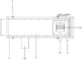
FIG. 1 is a front view of a high force shaker of the present invention;
FIG. 2 is a top view of a high force shaker of the present invention;
FIG. 3 is a schematic view of the structure of the collecting chamber of the present invention;
FIG. 4 is a schematic structural diagram of an electric cabinet according to the present invention;
fig. 5 is a schematic structural view of embodiment 3.
Reference numbers in the figures:
FIG. 1-fixed support; 2-powerful vibration motors; 3-vibrating the screen; 4-a feed inlet; 5, an electric cabinet; 6, collecting a bin; 7-a spring assembly; 8-a rotating shaft; 9-rotating rod; 10-a movable disc; 11-a connecting rod; 12-a turntable; 13-a connecting strap; 14-a discharge hole; 15-a feed roll; 16-a screen mesh; 17-a display screen; 18-power button; 19-control keys; 20-display lamps; 21-universal wheel.
Detailed Description
The technical solutions in the embodiments of the present invention will be clearly and completely described below with reference to the drawings in the embodiments of the present invention, and it is obvious that the described embodiments are only a part of the embodiments of the present invention, and not all of the embodiments. All other embodiments, which can be derived by a person skilled in the art from the embodiments given herein without making any creative effort, shall fall within the protection scope of the present invention.
As shown in the following fig. 1-4, a powerful vibrating screen comprises a fixed support 1, a powerful vibrating motor 2, a vibrating screen 3, a feeding port 4, an electric cabinet 5 and a collecting bin 6, wherein the powerful vibrating motor 2 is arranged on the fixed support 1, the powerful vibrating motor 2 is welded to the fixed support 1, the vibrating screen 3 is fixedly connected with the collecting bin 6, a rotating shaft 8 is arranged on the side surface of the powerful vibrating motor 2, the rotating shaft 8 is rotatably connected with the powerful vibrating motor 2, a rotating rod 9 is arranged between the vibrating screen 3 and the collecting bin 6, a feeding roller 15 is arranged inside the feeding port 4, a connecting rod 11 is arranged on the feeding roller 15, the connecting rod 11 is welded to the feeding roller 15, the connecting rod 11 penetrates through the feeding port 4 and is rotatably connected with the feeding port 4, a rotary disc 12 is arranged on the side surface of the connecting rod 11, the side face close to the powerful vibration motor 2 is provided with an electric cabinet 5, the electric cabinet 5 comprises a display lamp 20, a control key 19, a display screen 17 and a power button 18, the display screen 17 is arranged in the middle of the electric cabinet 5, the control key 19 is arranged below the display screen 17, the display lamp 20 is arranged below the control key 19, and the power button 18 is arranged on the side face of the display screen 17.
In this embodiment, electric cabinet 5 with the powerful vibration motor 2 is connected between the electricity, is connected with powerful vibration motor 2 electricity through electric cabinet 5, can reach the purpose of control powerful vibration motor 2 moving, during the use, can automatically regulated vibration frequency through electric cabinet 5, prevents that shale shaker 3 is too fast or leads to the screening inhomogeneous too slowly.
In this embodiment, dwang 9 and 8 sides of pivot all are provided with activity dish 10, activity dish 10 with be provided with connecting band 13 between the carousel 12, activity dish 10 through connecting band 13 with carousel 12 forms transmission cooperation, and when using, powerful vibrating motor 2 drives pivot 8 and rotates, and then pivot 8 makes dwang 9, connecting rod 11 and feeding roller 15 rotate through connecting band 13, and then reaches the purpose of powerful vibrating motor 2 drive feeding roller 15 pivoted, and then sieves the material.
In this embodiment, 3 sides of shale shaker are provided with spring assembly 7, spring assembly 7 with fixed bolster 1 fixed connection can make shale shaker 3 keep steady vibrations at vibrations in-process through setting up spring assembly 7, enables the material screening more even.
In this embodiment, the top of the collection bin 6 is provided with a screen 16, the screen 16 is connected with the collection bin 6 in a screw fixing manner, and the screen 16 is arranged to screen materials.
In the present embodiment, the side of the collecting bin 6 is provided with a discharge hole 14, and the material inside the collecting bin 6 can be discharged through the discharge hole 14.
In this embodiment, powerful vibrating motor 2 can be gasoline motor, diesel motor, has the characteristics that power is big, fixed bolster 1 adopts aluminum alloy material to make, has the light in weight, characteristics that intensity is big, spring assembly 7 adopts high elasticity spring and aluminum alloy plate to constitute, when using, can reduce the noise that produces when vibrations.
Example 1: as shown in figure 1, in specific use, materials are fed from a feeding hole 4, after the materials are electrified, a power supply button 18 is turned on, then an electric cabinet 5 is turned on, at the moment, a display lamp 20 on the electric cabinet 5 displays green, various parameters are set through a control key 19, the vibration frequency is adjusted, then a strong vibration motor 2 is controlled to operate through the electric cabinet 5, then the strong vibration motor 2 drives a rotating shaft 8 to rotate, further the rotating shaft 8 enables a rotating rod 9, a connecting rod 11 and a feeding roller 15 to rotate through a connecting belt 13, then the feeding roller 15 sucks the materials from the feeding hole 4 and sends the materials to a vibration screen 3 for screening, under the action of the strong vibration motor 2, the vibration screen 3 repeatedly moves up and down to screen the materials, the screened materials fall into a collecting bin 6 due to the action of gravity, at the moment, the screened materials are accumulated in the collecting bin 6, and when the quantity of the materials is increased, due to the action of gravity, the screened materials are discharged from the discharge hole 4 on the collecting bin 6, and after the materials in the collecting bin 6 are completely collected, the power button 18 is turned off, and the electric cabinet 5 is turned off to complete the whole screening process.
Example 2: as shown in fig. 1, the present embodiment is different from embodiment 1 in that: the inclination angles between the vibrating screen 3 and the collecting bin 6 and the fixed support 1 are 30 degrees, and the inclination angles are larger, so that the speed of materials entering the vibrating screen 3 and the collecting bin 6 is higher, the screening speed is higher, the screening efficiency is higher, when the device is used, the materials are fed from the feeding hole 4, after the device is electrified, the power button 18 is turned on, the electric cabinet 5 is further turned on, the display lamp 20 on the electric cabinet 5 displays green, various parameters are set through the control keys 19, the vibration frequency is adjusted, the strong vibration motor 2 is controlled to operate through the electric cabinet 5, the strong vibration motor 2 drives the rotating shaft 8 to rotate, the rotating shaft 8 enables the rotating rod 9, the connecting rod 11 and the feeding roller 15 to rotate through the connecting belt 13, the feeding roller 15 sucks the materials from the feeding hole 4 and sends the materials to the vibrating screen 3 for screening, under the action of the strong vibration motor 2, the repeated up-and-down motion of shale shaker 3 sieves the material, and the material falls into to collect the storehouse 6 because the action of gravity after the screening this moment, and the material after the screening is piled up in collecting the storehouse 6 this moment, and when material quantity increased, because the action of gravity, the material after the screening was discharged from collecting the discharge gate 14 on the storehouse 6, after collecting the material in the storehouse 6 completely, closed power button 18, closed electric cabinet 5 can accomplish whole screening process.
Example 3: as shown in fig. 5, the universal wheel 21 is arranged at the bottom of the fixing support 1, and the powerful vibrating screen can have stronger activity, is flexible and convenient and can be conveniently carried by arranging the universal wheel 21.
It will be evident to those skilled in the art that the utility model is not limited to the details of the foregoing illustrative embodiments, and that the present invention may be embodied in other specific forms without departing from the spirit or essential attributes thereof. The present embodiments are therefore to be considered in all respects as illustrative and not restrictive, the scope of the utility model being indicated by the appended claims rather than by the foregoing description, and all changes which come within the meaning and range of equivalency of the claims are therefore intended to be embraced therein. Any reference sign in a claim should not be construed as limiting the claim concerned.
Furthermore, it should be understood that although the present description refers to embodiments, not every embodiment may contain only a single embodiment, and such description is for clarity only, and those skilled in the art should integrate the description, and the embodiments may be combined as appropriate to form other embodiments understood by those skilled in the art.
Claims (6)
1. A powerful vibrating screen is characterized in that: the vibration sieve comprises a fixed support, a powerful vibration motor, a vibration sieve, a feed inlet, an electric cabinet and a collection bin, wherein the powerful vibration motor is arranged on the fixed support and is welded with the fixed support, the vibration sieve is fixedly connected with the collection bin, a rotating shaft is arranged on the side surface of the powerful vibration motor and is rotatably connected with the powerful vibration motor, a rotating rod is arranged between the vibration sieve and the collection bin, a feed roller is arranged in the feed inlet, a connecting rod is arranged on the feed roller and is welded with the feed roller, the connecting rod penetrates through the feed inlet and is rotatably connected with the feed inlet, a turntable is arranged on the side surface of the connecting rod, the electric cabinet is arranged on the side surface close to the powerful vibration motor, and comprises a display lamp, a control key, a display screen and a power button, the display screen is arranged in the middle of the electric cabinet, a control key is arranged below the display screen, a display lamp is arranged below the control key, and the power button is arranged on the side face of the display screen.
2. A power shaker as defined in claim 1, further comprising: the electric control box is electrically connected with the powerful vibration motor.
3. A power shaker as defined in claim 1, further comprising: dwang and pivot side all are provided with the activity dish, the activity dish with be provided with the connecting band between the carousel, the activity dish pass through the connecting band with the carousel forms transmission cooperation.
4. A power shaker as defined in claim 1, further comprising: the vibrating screen is characterized in that a spring assembly is arranged on the side face of the vibrating screen, and the spring assembly is fixedly connected with the fixed support.
5. A power shaker as defined in claim 1, further comprising: the top of collecting the storehouse is provided with the screen cloth, the screen cloth with collect between the storehouse and be connected through the screw fixation mode.
6. A power shaker as defined in claim 1, further comprising: and a discharge port is formed in the side surface of the collecting bin.
Priority Applications (1)
| Application Number | Priority Date | Filing Date | Title |
|---|---|---|---|
| CN202121884022.0U CN215465982U (en) | 2021-08-13 | 2021-08-13 | Strong vibrating screen |
Applications Claiming Priority (1)
| Application Number | Priority Date | Filing Date | Title |
|---|---|---|---|
| CN202121884022.0U CN215465982U (en) | 2021-08-13 | 2021-08-13 | Strong vibrating screen |
Publications (1)
| Publication Number | Publication Date |
|---|---|
| CN215465982U true CN215465982U (en) | 2022-01-11 |
Family
ID=79758933
Family Applications (1)
| Application Number | Title | Priority Date | Filing Date |
|---|---|---|---|
| CN202121884022.0U Expired - Fee Related CN215465982U (en) | 2021-08-13 | 2021-08-13 | Strong vibrating screen |
Country Status (1)
| Country | Link |
|---|---|
| CN (1) | CN215465982U (en) |
-
2021
- 2021-08-13 CN CN202121884022.0U patent/CN215465982U/en not_active Expired - Fee Related
Similar Documents
| Publication | Publication Date | Title |
|---|---|---|
| CN217911548U (en) | Oyster peptide production is with preventing blockking up shale shaker | |
| CN207887511U (en) | A kind of oscillatory type Sand screen for building | |
| CN114526645A (en) | Production device and production method of solid primer for fireworks and crackers leads | |
| CN211488497U (en) | Screening plant for agricultural products | |
| CN119216017A (en) | A raw material crushing and screening device for manufacturing activated carbon | |
| CN213644866U (en) | Concrete raw materials screening grading plant | |
| CN108212772A (en) | A kind of automatic blanking sieve | |
| CN215964715U (en) | Vibrating screen screening device | |
| CN219150762U (en) | Vibrating screen | |
| CN218282630U (en) | Vibrating soil screening machine | |
| CN216322117U (en) | Milling equipment is used in spices processing | |
| CN216571718U (en) | High-efficiency mobile garbage recycling station capable of separating solid from liquid | |
| CN210207586U (en) | Agricultural seed classified collection device | |
| CN218222673U (en) | Powder screening device suitable for production of rubber vulcanization accelerator | |
| CN211756761U (en) | Novel vibrating quartz sand screening device | |
| CN210097857U (en) | Rubbing crusher that possesses screening function | |
| CN224181305U (en) | Biax shale shaker with even screening function | |
| CN207899741U (en) | A kind of vibration sand device with cast hopper | |
| CN218360617U (en) | Novel sample separating screen | |
| CN223616220U (en) | High-frequency vibrating screen for iron ore dressing | |
| CN211070838U (en) | A sieve bed device for cement manufacture | |
| CN2041980U (en) | Complex-frequency rotary vibration sieve | |
| CN223145278U (en) | A rotary grading screen for packaging in feed production | |
| CN113499818A (en) | Manufacturing process and device of environment-friendly new printing material | |
| CN223970111U (en) | High efficiency shaking table device |
Legal Events
| Date | Code | Title | Description |
|---|---|---|---|
| GR01 | Patent grant | ||
| GR01 | Patent grant | ||
| CF01 | Termination of patent right due to non-payment of annual fee |
Granted publication date: 20220111 |
|
| CF01 | Termination of patent right due to non-payment of annual fee |