CN215463576U - Rotor structure of industrial coating dispersion machine - Google Patents
Rotor structure of industrial coating dispersion machine Download PDFInfo
- Publication number
- CN215463576U CN215463576U CN202120825480.0U CN202120825480U CN215463576U CN 215463576 U CN215463576 U CN 215463576U CN 202120825480 U CN202120825480 U CN 202120825480U CN 215463576 U CN215463576 U CN 215463576U
- Authority
- CN
- China
- Prior art keywords
- main shaft
- pipe
- chassis
- circular plate
- cavity
- Prior art date
- Legal status (The legal status is an assumption and is not a legal conclusion. Google has not performed a legal analysis and makes no representation as to the accuracy of the status listed.)
- Active
Links
- 239000006115 industrial coating Substances 0.000 title claims abstract description 17
- 239000006185 dispersion Substances 0.000 title description 7
- 238000003756 stirring Methods 0.000 claims abstract description 18
- 239000000463 material Substances 0.000 claims description 4
- 239000011248 coating agent Substances 0.000 claims description 3
- 238000000576 coating method Methods 0.000 claims description 3
- 238000007789 sealing Methods 0.000 description 10
- 239000012530 fluid Substances 0.000 description 8
- XLYOFNOQVPJJNP-UHFFFAOYSA-N water Substances O XLYOFNOQVPJJNP-UHFFFAOYSA-N 0.000 description 6
- 230000000694 effects Effects 0.000 description 4
- 238000000034 method Methods 0.000 description 4
- 230000008569 process Effects 0.000 description 4
- 239000000243 solution Substances 0.000 description 3
- 238000010586 diagram Methods 0.000 description 2
- 230000007246 mechanism Effects 0.000 description 2
- 230000004075 alteration Effects 0.000 description 1
- 230000009286 beneficial effect Effects 0.000 description 1
- 230000008878 coupling Effects 0.000 description 1
- 238000010168 coupling process Methods 0.000 description 1
- 238000005859 coupling reaction Methods 0.000 description 1
- 238000002347 injection Methods 0.000 description 1
- 239000007924 injection Substances 0.000 description 1
- 238000012986 modification Methods 0.000 description 1
- 230000004048 modification Effects 0.000 description 1
- 238000006467 substitution reaction Methods 0.000 description 1
- 230000001960 triggered effect Effects 0.000 description 1
- 230000003245 working effect Effects 0.000 description 1
Images


Landscapes
- Accessories For Mixers (AREA)
Abstract
The utility model relates to the technical field of rotor structures, in particular to a rotor structure of an industrial coating dispersing machine, which comprises a main shaft, wherein two stirring rods are symmetrically distributed around the main shaft, the end parts of the stirring rods are fixedly connected with a supporting plate, one end of the supporting plate is fixed on the main shaft, the bottom end of the main shaft is provided with a chassis, one end of the main shaft extends into a circular plate groove formed in the chassis, a clamping ring is fixedly sleeved on the outer wall of the end part of the main shaft, and a circular plate groove is formed in the bottom surface of the end part of the main shaft.
Description
Technical Field
The utility model relates to the technical field of rotor structures, in particular to a rotor structure of an industrial coating dispersion machine.
Background
The industrial coating stirring dispersion machine in the prior art works, the industrial coating is stirred by the rotor, the uniform texture of the industrial coating is ensured, the rotor is improved, the automation degree of the rotor is improved, and the industrial coating stirring dispersion machine has important significance for the coating industry.
If the rotor structure can be invented, the double effects of rotating and dispersing the coating and automatically injecting water can be realized, the function is stable and strong, the problem can be solved, and the rotor structure of the industrial coating dispersing machine is provided for the purpose.
SUMMERY OF THE UTILITY MODEL
The utility model aims to provide a rotor structure of an industrial coating material dispenser, which aims to solve the problems in the prior art.
In order to achieve the purpose, the utility model provides the following technical scheme: a rotor structure of an industrial coating dispersion machine comprises a main shaft, wherein two stirring rods which are symmetrically distributed are arranged around the main shaft, a supporting plate is fixedly connected to the end part of each stirring rod, one end of each supporting plate is fixed on the main shaft, a chassis is arranged at the bottom end of the main shaft, one end of the main shaft extends into a circular plate groove formed in the chassis, a clamping ring is fixedly sleeved on the outer wall of the end part of the main shaft, a circular plate groove is formed in the bottom surface of the end part of the main shaft, two vertical pipes which are symmetrically distributed are arranged in the circular plate groove of the main shaft, a spring, an interception cylinder and a control column are arranged in each vertical pipe, one end of the spring is in contact with the interception cylinder, the other end of the spring is in contact with the control column, one end of the control column extends out of each vertical pipe, a hemispherical block is arranged at one end of each vertical pipe, a main pipe cavity and a branch pipe cavity are formed in the main shaft, a plurality of branch pipe cavities which are uniformly arranged in a ring manner are communicated with each other, one end of the branch pipe cavity extends to the outside of the main shaft, one end of the hard pipe extends to the circular plate groove of the main shaft, the other end of the hard pipe extends to the main pipe cavity, a plurality of semi-sphere blocks which are uniformly distributed are arranged in the circular plate of the main shaft, the semi-sphere blocks are fixed on the chassis, an L-shaped pipe cavity is arranged in the chassis, one end of the L-shaped pipe cavity extends to the cylindrical groove in the main shaft, the other end of the L-shaped pipe cavity extends to the outside of the chassis, two control valves are arranged in the hard pipe, and the two control valves are arranged on two sides of a connector of the vertical pipe and the hard pipe.
Preferably, the control valve includes annular piece, L template and seal receptacle, middle part one side of annular piece is provided with the seal receptacle, and the seal receptacle shape is the circular disk one side body coupling round platform, and the round platform of seal receptacle is most advanced to be protruded to the annular piece in, and the ring is equipped with a plurality of evenly distributed's L template around the seal receptacle, and L template one end is fixed on the annular piece, and the other end of L template is protruded to in the spout of seting up on the circular disk lateral wall of seal receptacle.
Preferably, the intercepting cylinder is fixed on the wall of an inner cavity of the vertical pipe, the control column is cylindrical, the column body is movably sleeved in the inner cavity of the vertical pipe, a protruding sliding block is fixed on the inner wall of the vertical pipe on one side of the control column, and the protruding sliding block is arranged in a sliding groove formed in the side wall of the control column.
Preferably, the clamping ring is in an annular plate shape, the clamping ring is arranged in an annular groove formed in the inner side wall of a circular plate groove of the chassis in a matching mode, and the bottom end of the main shaft is movably sleeved in the circular plate groove of the chassis.
Compared with the prior art, the utility model has the beneficial effects that:
1. the utility model realizes double working effects by the structural design, one is the rotation of the rotor to stir and disperse the industrial coating, and the other is the rotation process of the main shaft relative to the chassis, which provides power for the water flow movement in the main shaft to force the water flow to be uniformly dispersed out through the main shaft, thereby achieving the effect of automatic water injection;
2. the control column is forced to reciprocate by the control column through the semi-spherical blocks which are arranged in a ring one by one and the semi-spherical blocks and the spring are matched, so that the fluid in the main shaft is triggered to flow in a single direction, and the stable flow control effect in the main shaft is realized through the exquisite part design.
Drawings
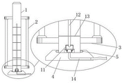
FIG. 1 is a schematic structural view of the present invention;
FIG. 2 is a diagram of a hard tube position distribution;
fig. 3 is a schematic structural diagram of a in fig. 2.
In the figure: the device comprises a main shaft 1, a stirring rod 2, a supporting plate 3, a chassis 4, a clamping ring 5, a vertical pipe 6, a spring 7, an intercepting cylinder 8, a control column 9, a hemispherical block 10, a hard pipe 11, a main pipe cavity 12, a branch pipe cavity 13, an L-shaped pipe cavity 14, a control valve 15, an annular sheet 16, an L-shaped plate 17 and a sealing seat 18.
Detailed Description
The technical solutions in the embodiments of the present invention will be clearly and completely described below with reference to the drawings in the embodiments of the present invention, and it is obvious that the described embodiments are only a part of the embodiments of the present invention, and not all of the embodiments. All other embodiments obtained by those skilled in the art without creative efforts based on the technical solutions of the present invention belong to the protection scope of the present invention.
Referring to fig. 1 to 3, the present invention provides a technical solution: a rotor structure of an industrial coating dispersion machine comprises a main shaft 1, two stirring rods 2 which are symmetrically distributed are arranged around the main shaft 1, a supporting plate 3 is fixedly connected to the end part of each stirring rod 2, one end of each supporting plate 3 is fixed on the main shaft 1, a chassis 4 is arranged at the bottom end of the main shaft 1, one end of the main shaft 1 extends into a circular plate groove formed in the chassis 4, a clamping ring 5 is fixedly sleeved on the outer wall of the end part of the main shaft 1, a circular plate groove is formed in the bottom surface of the end part of the main shaft 1, two vertical pipes 6 which are symmetrically distributed are arranged in the circular plate groove of the main shaft 1, a spring 7, an intercepting cylinder 8 and a control column 9 are arranged in the vertical pipe 6, one end of the spring 7 is contacted with the intercepting cylinder 8, the other end of the spring 7 is contacted with the control column 9, one end of the control column 9 extends to the outside of the vertical pipe 6, a hemispherical block 10 is arranged at one end of the vertical pipe 6, a hard pipe 11 is fixedly connected to the other end of the vertical pipe 6, a main pipe cavity 12 and branch pipe cavities 13 are arranged in a main shaft 1, a plurality of branch pipe cavities 13 uniformly arranged in a ring are communicated around the main pipe cavity 12, one end of each branch pipe cavity 13 extends to the outside of the main shaft 1, one end of a hard pipe 11 extends into a circular plate groove of the main shaft 1, the other end of the hard pipe 11 extends into the main pipe cavity 12, a plurality of uniformly distributed hemispherical blocks 10 are arranged in the circular plate of the main shaft 1, the hemispherical blocks 10 are fixed on a chassis 4, an L-shaped pipe cavity 14 is arranged in the chassis 4, one end of the L-shaped pipe cavity 14 extends into a cylindrical groove on the main shaft 1, the other end of the L-shaped pipe cavity 14 extends to the outside of the chassis 4, two control valves 15 are arranged in the hard pipe 11, the two control valves 15 are arranged at two sides of a joint of a stand pipe 6 and the hard pipe 11, referring to figure 1, a hose is fixed at one side of the chassis 4, the hose extends to the outside of the whole stirring mechanism and is connected with a water supply device, the upper end of the main shaft 1 is connected with a stirring mechanism in the prior art, so that a rotor structure is arranged in a stirring barrel, industrial coating is stirred by rotation, and the chassis 4 is fixed at the bottom of the stirring barrel.
The control valve 15 comprises an annular sheet 16, an L-shaped plate 17 and a sealing seat 18, the sealing seat 18 is arranged on one side of the middle of the annular sheet 16, the sealing seat 18 is in the shape of a circular plate integrally connected with a circular table on one side of the circular plate, the tip of the circular table of the sealing seat 18 protrudes into the annular sheet 16, a plurality of L-shaped plates 17 which are uniformly distributed are annularly arranged around the sealing seat 18, one end of each L-shaped plate 17 is fixed on the annular sheet 16, and the other end of each L-shaped plate 17 protrudes into a sliding groove formed in the side wall of the circular plate of the sealing seat 18.
The intercepting cylinder 8 is fixed on the wall of the inner cavity of the vertical pipe 6, the control column 9 is cylindrical and the column body is movably sleeved in the inner cavity of the vertical pipe 6, a convex sliding block is fixed on the inner wall of the vertical pipe 6 on one side of the control column 9, and the convex sliding block is arranged in a sliding groove formed in the side wall of the control column 9.
The clamping ring 5 is in an annular plate shape, the clamping ring 5 is arranged in an annular groove formed in the inner side wall of a circular plate groove of the chassis 4 in a matching mode, and the bottom end of the main shaft 1 is movably sleeved in the circular plate groove of the chassis 4.
The working principle is as follows: the main shaft 1 drives the hard tube 11 in the rotation process, the hard tube 11 drives the stand tube 6 and further drives the control column 9 to move, the control column 9 passes through the plurality of hemispherical blocks 10 one by one in the movement process, the hemispherical blocks 10 stir the control column 9 to force the control column 9 to retract into the stand tube 6, thus fluid in the hard tube 11 is forced to be injected into the main tube cavity 12, then the spring 7 rebounds to push the control column 9, the control column 9 extends out of the stand tube 6 again, fluid is required to be supplemented into the hard tube 11 in the process, the fluid comes from a circular plate groove of the main shaft 1, because the control valve 15 has the effect of one-way control fluid, the fluid can only be the fluid to jack up the sealing seat 18 through the control valve 15, and then the sealing seat 18 is directly driven to block the annular sheet 16 through a channel between the annular sheet 16 and the sealing seat 18 in a reverse flow manner, so that the control column 9 is forced to reciprocate by the movement of the stand tube 6, the control column 9 provides motive force for the movement of the fluid, so that the water flow is injected into the circular plate groove of the main shaft 1 through the L-shaped pipe cavity 14, then injected into the main pipe cavity 12 through the hard pipe 11, and then diffused out through the plurality of branch pipe cavities 13.
Although embodiments of the present invention have been shown and described, it will be appreciated by those skilled in the art that changes, modifications, substitutions and alterations can be made in these embodiments without departing from the principles and spirit of the utility model, the scope of which is defined in the appended claims and their equivalents.
Claims (4)
1. The utility model provides an industry coating dispenser rotor structure, includes main shaft (1), its characterized in that: the stirring device is characterized in that two stirring rods (2) are symmetrically distributed around the main shaft (1), the end parts of the stirring rods (2) are fixedly connected with a supporting plate (3), one end of the supporting plate (3) is fixed on the main shaft (1), the bottom end of the main shaft (1) is provided with a chassis (4), one end of the main shaft (1) extends into a circular plate groove formed in the chassis (4), a clamping ring (5) is fixedly sleeved on the outer wall of the end part of the main shaft (1), the circular plate groove is formed in the bottom surface of the end part of the main shaft (1), two vertical pipes (6) are symmetrically distributed in the circular plate groove of the main shaft (1), a spring (7), an intercepting cylinder (8) and a control column (9) are arranged in each vertical pipe (6), one end of the spring (7) is in contact with the intercepting cylinder (8), the other end of the spring (7) is in contact with the control column (9), one end of the control column (9) extends to the outside of the vertical pipe (6), one end of the vertical pipe (6) is provided with a hemispherical block (10), the other end of the vertical pipe (6) is fixedly connected with a hard pipe (11), a main pipe cavity (12) and a branch pipe cavity (13) are arranged in the main shaft (1), the periphery of the main pipe cavity (12) is communicated with a plurality of branch pipe cavities (13) which are uniformly and annularly arranged, one ends of the branch pipe cavities (13) extend to the outside of the main shaft (1), one ends of the hard pipes (11) extend into a circular plate groove of the main shaft (1), the other ends of the hard pipes (11) extend into the main pipe cavity (12), the circular plate middle ring of the main shaft (1) is provided with a plurality of uniformly distributed hemispherical blocks (10), the hemispherical blocks (10) are fixed on the chassis (4), an L-shaped pipe cavity (14) is arranged in the chassis (4), one end of the L-shaped pipe cavity (14) extends into a cylindrical groove on the main shaft (1), and the other end of the L-shaped pipe cavity (14) extends to the outside of the chassis (4), two control valves (15) are arranged in the hard pipe (11), and the two control valves (15) are arranged on two sides of the interface of the vertical pipe (6) and the hard pipe (11).
2. The industrial coating material dispenser rotor structure of claim 1, wherein: control valve (15) include annular piece (16), L template (17) and seal receptacle (18), middle part one side of annular piece (16) is provided with seal receptacle (18), and seal receptacle (18) shape is the integrative round platform of connecting of plectane one side, and the round platform of seal receptacle (18) is most advanced to be protruded to annular piece (16), and encircles L template (17) that are equipped with a plurality of evenly distributed around seal receptacle (18), and L template (17) one end is fixed on annular piece (16), and the other end of L template (17) is protruded to in the spout of seting up on the plectane lateral wall of seal receptacle (18).
3. The industrial coating material dispenser rotor structure of claim 1, wherein: the intercepting cylinder (8) is fixed on the wall of an inner cavity of the vertical pipe (6), the control column (9) is cylindrical and the column body is movably sleeved in the inner cavity of the vertical pipe (6), a protruding sliding block is fixed on the inner wall of the vertical pipe (6) on one side of the control column (9), and the protruding sliding block is arranged in a sliding groove formed in the side wall of the control column (9).
4. The industrial coating material dispenser rotor structure of claim 1, wherein: the clamping ring (5) is in an annular plate shape, the clamping ring (5) is arranged in an annular groove formed in the inner side wall of a circular plate groove of the chassis (4) in a matching mode, and the bottom end of the main shaft (1) is movably sleeved in the circular plate groove of the chassis (4).
Priority Applications (1)
| Application Number | Priority Date | Filing Date | Title |
|---|---|---|---|
| CN202120825480.0U CN215463576U (en) | 2021-04-21 | 2021-04-21 | Rotor structure of industrial coating dispersion machine |
Applications Claiming Priority (1)
| Application Number | Priority Date | Filing Date | Title |
|---|---|---|---|
| CN202120825480.0U CN215463576U (en) | 2021-04-21 | 2021-04-21 | Rotor structure of industrial coating dispersion machine |
Publications (1)
| Publication Number | Publication Date |
|---|---|
| CN215463576U true CN215463576U (en) | 2022-01-11 |
Family
ID=79775436
Family Applications (1)
| Application Number | Title | Priority Date | Filing Date |
|---|---|---|---|
| CN202120825480.0U Active CN215463576U (en) | 2021-04-21 | 2021-04-21 | Rotor structure of industrial coating dispersion machine |
Country Status (1)
| Country | Link |
|---|---|
| CN (1) | CN215463576U (en) |
-
2021
- 2021-04-21 CN CN202120825480.0U patent/CN215463576U/en active Active
Similar Documents
| Publication | Publication Date | Title |
|---|---|---|
| CN111976105B (en) | Handling frame with circumference shape shoe mold | |
| CN109042236A (en) | A kind of agricultural irrigation machine | |
| CN206793660U (en) | A kind of vertical response kettle | |
| CN215138909U (en) | A kind of raw material proportioning device for polyether polyol production | |
| CN111893688B (en) | Pneumatic homogenizing device for dye of dyeing machine | |
| CN111760514A (en) | Liquid stirring device with good mixing effect for machining | |
| CN216692215U (en) | Lead-free angle valve | |
| CN216924026U (en) | Precise quantitative material conveying device for pinch valve plunger | |
| CN210799248U (en) | A linkage pumping mechanism to avoid backflow | |
| CN113023138A (en) | Mechanism of pomegranate extract impulse type addition in cosmetics cooling tank | |
| CN113385133B (en) | Reaction device of lanthanum oxide mixed water for lanthanum hydroxide production | |
| CN224236743U (en) | Lifting auxiliary agent adding device based on PVC production | |
| CN201610951U (en) | High pressure ball valve | |
| CN220803267U (en) | Hydrolysis device for glucosamine hydrochloride production | |
| CN209456266U (en) | A kind of stalk feces of livestock and poultry pumping system | |
| CN208959674U (en) | Agitator tank is used in a kind of production of silicone oil | |
| CN218873141U (en) | Gas cleaning pipe for packaging concentration line | |
| CN219926991U (en) | Oil press with quick lifting function | |
| CN214937326U (en) | A saccharification tank device for beer production | |
| CN219447989U (en) | Slurry storage tank | |
| CN217313028U (en) | An easy-to-remove pesticide production and processing stirring device | |
| CN221374618U (en) | High pressure difference fixed cone valve | |
| CN214787455U (en) | Novel cartridge formula becket linear sealing switching-over valve | |
| CN222959060U (en) | Mixing device of injection molding machine | |
| CN223654937U (en) | Preparation device of chemical nickel working solution |
Legal Events
| Date | Code | Title | Description |
|---|---|---|---|
| GR01 | Patent grant | ||
| GR01 | Patent grant |