Intelligent cabinet of integration that intelligent degree is high
Technical Field
The utility model relates to the technical field of cabinets, in particular to an integrated intelligent cabinet with high intelligent degree.
Background
The cabinet is indispensable composition part in the electrical equipment, is electrical control equipment's carrier, generally forms by cold-rolled steel sheet or alloy preparation, can provide the guard action such as waterproof, dustproof, electromagnetic interference resistance to depositing equipment, and current cabinet is at during operation intelligent degree low, and thus unable intelligent accuse temperature to and unable high temperature early warning, for this reason, we propose an integration intelligent cabinet that intelligent degree is high.
SUMMERY OF THE UTILITY MODEL
Solves the technical problem
Aiming at the defects of the prior art, the utility model provides an integrated intelligent cabinet with high intelligent degree, which has the advantage of high intelligent degree and solves the problems that the intelligent degree of the existing cabinet is low during working, so that intelligent temperature control cannot be realized, and high-temperature early warning cannot be realized.
Technical scheme
In order to achieve the purpose, the utility model provides the following technical scheme: an integrated intelligent cabinet with high intelligent degree comprises a cabinet body, wherein a motor is arranged at the left bottom of an inner cavity of the cabinet body, a driving gear is fixedly connected with a middle shaft on the surface of an output end of the motor, a first fan blade is fixedly connected with the top of the surface of the output end of the motor, an auxiliary gear is meshed with the right side of the driving gear, a driven gear is meshed with the right side of the auxiliary gear, a rotating shaft is fixedly connected with an inner cavity of the driven gear, a second fan blade is fixedly connected with the top of the surface of the rotating shaft, a hollow pipe is fixedly connected with the inner cavity of the auxiliary gear, an exhaust pipe is movably connected with the bottom of the inner cavity of the hollow pipe, a fan is fixedly connected with the bottom of the exhaust pipe, an exhaust pipe is fixedly connected with the bottom of the fan, a through hole is formed in the surface of the hollow pipe, a transverse pipe is communicated with the top of the hollow pipe, and exhaust heads are communicated with two sides of the bottom of the transverse pipe, the bottom fixedly connected with temperature sensor that the right side of the cabinet body inner chamber and lie in axis department, the right side fixedly connected with buzzer of the cabinet body.
Preferably, the bottom of the cabinet body is embedded with a dustproof screen plate, the two sides of the fan are fixedly connected with fixing frames, and one side of each fixing frame is fixedly connected with the dustproof screen plate.
Preferably, the left side of the inner cavity of the cabinet body and the bottom of the middle shaft are fixedly connected with a PLC (programmable logic controller), the PLC is electrically connected with the temperature sensor in a bidirectional mode, and the output end of the PLC is electrically connected with the input end of the buzzer in a unidirectional mode.
Preferably, the inner wall of the cabinet body is fixedly connected with a pore plate at the bottom of the temperature sensor, and heat dissipation holes are formed in the middle shafts at two sides of the cabinet body.
Preferably, the top of the outer surface of the exhaust pipe is fixedly connected with a sealing ring, and the outer surface of the sealing ring is in contact with the hollow pipe.
Preferably, the bottom of motor is fixedly connected with the backup pad, and the left side and the cabinet body fixed connection of backup pad.
Advantageous effects
Compared with the prior art, the utility model provides an integrated intelligent cabinet with high intelligent degree, which has the following beneficial effects:
1. the utility model sets two-gear temperature value through the PLC controller, when the temperature sensor detects that the temperature is higher than a first-gear set value and lower than a second-gear set value, the PLC controller can control the motor and the fan to work, the outside gas is pumped in through the matching of the exhaust pipe, the hollow pipe, the through hole, the transverse pipe and the exhaust head and then is exhausted into the cabinet body, the output end of the motor drives the driving gear and the first fan blade to rotate, the driving gear drives the auxiliary gear to rotate, the auxiliary gear drives the hollow pipe and the driven gear to rotate, the driven gear drives the rotating shaft to rotate, the rotating shaft drives the second fan blade to rotate, the gas is blown upwards from the bottom, the hollow pipe drives the transverse pipe to rotate, the transverse pipe drives the exhaust head to rotate, the air flow rate in the cabinet body can be accelerated, the hot gas in the cabinet body is exhausted through the heat dissipation hole, when the temperature sensor detects that the temperature is higher than the second-gear set value, the PLC controller can control the buzzer to give an alarm, the alarm is reminded to workers, the workers can check whether the inner parts of the cabinet are damaged or not in time, and the problems that the existing cabinet is low in intelligent degree during working, intelligent temperature control cannot be achieved, and high-temperature early warning cannot be achieved are solved.
2. The dustproof screen plate is arranged, so that the dustproof effect is achieved, dust is prevented from entering the cabinet body along with airflow, the exhaust pipe is in close contact with the hollow pipe through the sealing ring, the phenomenon of poor sealing effect is avoided, the work of the motor is stabilized through the supporting plate, and the motor is limited.
Drawings
FIG. 1 is a schematic structural view of the present invention;
FIG. 2 is a schematic cross-sectional view of the present invention;
FIG. 3 is a partial bottom view of the present invention;
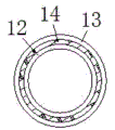
FIG. 4 is a schematic perspective view of the hollow tube of the present invention.
In the figure: 1. a cabinet body; 2. a motor; 3. a driving gear; 4. a first fan blade; 5. an auxiliary gear; 6. a driven gear; 7. a rotating shaft; 8. a second fan blade; 9. an orifice plate; 10. a fan; 11. an air exhaust pipe; 12. an exhaust pipe; 13. a hollow tube; 14. a seal ring; 15. a through hole; 16. a transverse tube; 17. an exhaust head; 18. a PLC controller; 19. a temperature sensor; 20. a buzzer.
Detailed Description
The technical solutions in the embodiments of the present invention will be clearly and completely described below with reference to the drawings in the embodiments of the present invention, and it is obvious that the described embodiments are only a part of the embodiments of the present invention, and not all of the embodiments. All other embodiments, which can be derived by a person skilled in the art from the embodiments given herein without making any creative effort, shall fall within the protection scope of the present invention.
In the description of the present invention, it should be noted that the terms "upper", "lower", "inner", "outer", "front", "rear", "both ends", "one end", "the other end", and the like indicate orientations or positional relationships based on the orientations or positional relationships shown in the drawings, and are only for convenience of describing the present invention and simplifying the description, but do not indicate or imply that the referred device or element must have a specific orientation, be constructed in a specific orientation, and be operated, and thus, should not be construed as limiting the present invention. Furthermore, the terms "first" and "second" are used for descriptive purposes only and are not to be construed as indicating or implying relative importance.
In the description of the present invention, it is to be noted that, unless otherwise explicitly specified or limited, the terms "mounted", "provided", "connected", and the like are to be construed broadly, such as "connected", which may be fixedly connected, detachably connected, or integrally connected; can be mechanically or electrically connected; they may be connected directly or indirectly through intervening media, or they may be interconnected between two elements. The specific meanings of the above terms in the present invention can be understood in specific cases to those skilled in the art.
The cabinet body 1, the motor 2, the driving gear 3, the first fan blade 4, the auxiliary gear 5, the driven gear 6, the rotating shaft 7, the second fan blade 8, the orifice plate 9, the fan 10, the exhaust pipe 11, the exhaust pipe 12, the hollow pipe 13, the sealing ring 14, the through hole 15, the transverse pipe 16, the exhaust head 17, the PLC controller 18, the temperature sensor 19 and the buzzer 20 are all universal standard parts or parts known by a person skilled in the art, and the structure and the principle of the utility model can be known by technical manuals or conventional experimental methods.
Referring to fig. 1-4, an integrated intelligent cabinet with high intelligence degree comprises a cabinet body 1, a pore plate 9 is fixedly connected to the inner wall of the cabinet body 1 and positioned at the bottom of a temperature sensor 19, heat dissipation holes are formed in the center shafts on the two sides of the cabinet body 1, a motor 2 is arranged at the bottom of the left side of the inner cavity of the cabinet body 1, a support plate is fixedly connected to the bottom of the motor 2, the left side of the support plate is fixedly connected to the cabinet body 1, the work of the motor 2 is stabilized by the support plate, the motor 2 is limited, a driving gear 3 is fixedly connected to the center shaft on the surface of the output end of the motor 2, a first fan blade 4 is fixedly connected to the top of the surface of the output end of the motor 2, an auxiliary gear 5 is engaged to the right side of the driving gear 3, a driven gear 6 is engaged to the right side of the auxiliary gear 5, a rotating shaft 7 is fixedly connected to the inner cavity of the driven gear 6, and a second fan blade 8 is fixedly connected to the top of the surface of the rotating shaft 7, the inner cavity of the auxiliary gear 5 is fixedly connected with a hollow pipe 13, the bottom of the inner cavity of the hollow pipe 13 is movably connected with an exhaust pipe 12, the top of the outer surface of the exhaust pipe 12 is fixedly connected with a sealing ring 14, the outer surface of the sealing ring 14 is contacted with the hollow pipe 13, the exhaust pipe 12 is in close contact with the hollow pipe 13 by arranging the sealing ring 14, the phenomenon of poor sealing effect is avoided, the bottom of the exhaust pipe 12 is fixedly connected with a fan 10, a dustproof screen plate is embedded at the bottom of the cabinet body 1, both sides of the fan 10 are fixedly connected with a fixed frame, one side of the fixed frame is fixedly connected with the dustproof screen plate, the dustproof screen plate is arranged to play a dustproof role, dust is prevented from entering the cabinet body 1 along with air flow, the bottom of the fan 10 is fixedly connected with an exhaust pipe 11, the surface of the hollow pipe 13 is provided with through holes 15, the top of the hollow pipe 13 is communicated with a transverse pipe 16, both sides of the bottom of the transverse pipe 16 are communicated with exhaust heads 17, the right side of the cabinet body 1 inner chamber is located the bottom fixedly connected with temperature sensor 19 of axis department, the right side fixedly connected with buzzer 20 of the cabinet body 1, the left side of the cabinet body 1 inner chamber is located the bottom fixedly connected with PLC controller 18 of axis department, PLC controller 18 and the two-way electric connection of temperature sensor 19, the output of PLC controller 18 and the one-way electric connection of the input of buzzer 20.
When the air flow velocity regulator is used, two-gear temperature values are set through the PLC 18, when the temperature sensor 19 detects that the temperature is higher than a first-gear set value and lower than a second-gear set value, the PLC 18 controls the motor 2 and the fan 10 to work, external air is sucked in through the cooperation of the exhaust pipe 11, the exhaust pipe 12, the hollow pipe 13, the through hole 15, the transverse pipe 16 and the exhaust head 17 and then exhausted into the cabinet body 1, the driving gear 3 and the first fan blade 4 are driven to rotate through the output end of the motor 2, the driving gear 3 drives the auxiliary gear 5 to rotate, the auxiliary gear 5 drives the hollow pipe 13 and the driven gear 6 to rotate, the driven gear 6 drives the rotating shaft 7 to rotate, the rotating shaft 7 drives the second fan blade 8 to rotate, air is blown upwards from the bottom, meanwhile, the hollow pipe 13 drives the transverse pipe 16 to rotate, the transverse pipe 16 drives the exhaust head 17 to rotate, and the air flow velocity inside the cabinet body 1 can be accelerated, make the inside steam of the cabinet body 1 pass through the louvre and discharge, after temperature sensor 19 detected the temperature value and is higher than second grade setting value, PLC controller 18 can control bee calling organ 20 and send out the police dispatch newspaper, reminds the staff, makes things convenient for the staff in time to inspect whether the rack inner part takes place to damage, has solved current rack and has hanged down at during operation intelligent degree to unable intelligence accuse temperature to and the problem of unable high temperature early warning.
Although embodiments of the present invention have been shown and described, it will be appreciated by those skilled in the art that changes, modifications, substitutions and alterations can be made in these embodiments without departing from the principles and spirit of the utility model, the scope of which is defined in the appended claims and their equivalents.