CN215419616U - Little electric wire netting energy storage conversion governing system - Google Patents
Little electric wire netting energy storage conversion governing system Download PDFInfo
- Publication number
- CN215419616U CN215419616U CN202123076437.8U CN202123076437U CN215419616U CN 215419616 U CN215419616 U CN 215419616U CN 202123076437 U CN202123076437 U CN 202123076437U CN 215419616 U CN215419616 U CN 215419616U
- Authority
- CN
- China
- Prior art keywords
- energy storage
- power generation
- converter
- alternating current
- photovoltaic power
- Prior art date
- Legal status (The legal status is an assumption and is not a legal conclusion. Google has not performed a legal analysis and makes no representation as to the accuracy of the status listed.)
- Active
Links
- 238000004146 energy storage Methods 0.000 title claims abstract description 103
- 238000006243 chemical reaction Methods 0.000 title claims abstract description 29
- 238000010248 power generation Methods 0.000 claims abstract description 57
- 238000004891 communication Methods 0.000 claims abstract description 28
- 238000001514 detection method Methods 0.000 claims abstract description 23
- 230000002457 bidirectional effect Effects 0.000 claims description 32
- 230000005611 electricity Effects 0.000 abstract description 12
- 230000009466 transformation Effects 0.000 description 5
- 238000007599 discharging Methods 0.000 description 2
- 238000012806 monitoring device Methods 0.000 description 2
- 230000001105 regulatory effect Effects 0.000 description 2
- RYGMFSIKBFXOCR-UHFFFAOYSA-N Copper Chemical compound [Cu] RYGMFSIKBFXOCR-UHFFFAOYSA-N 0.000 description 1
- 238000010521 absorption reaction Methods 0.000 description 1
- 239000002253 acid Substances 0.000 description 1
- 230000009286 beneficial effect Effects 0.000 description 1
- 229910052799 carbon Inorganic materials 0.000 description 1
- 230000001276 controlling effect Effects 0.000 description 1
- 229910052802 copper Inorganic materials 0.000 description 1
- 239000010949 copper Substances 0.000 description 1
- 230000007547 defect Effects 0.000 description 1
- 238000010586 diagram Methods 0.000 description 1
- 238000005265 energy consumption Methods 0.000 description 1
- GELKBWJHTRAYNV-UHFFFAOYSA-K lithium iron phosphate Chemical compound [Li+].[Fe+2].[O-]P([O-])([O-])=O GELKBWJHTRAYNV-UHFFFAOYSA-K 0.000 description 1
- 238000012986 modification Methods 0.000 description 1
- 230000004048 modification Effects 0.000 description 1
- 238000012544 monitoring process Methods 0.000 description 1
- 238000005070 sampling Methods 0.000 description 1
- 230000002269 spontaneous effect Effects 0.000 description 1
Images
Classifications
-
- Y—GENERAL TAGGING OF NEW TECHNOLOGICAL DEVELOPMENTS; GENERAL TAGGING OF CROSS-SECTIONAL TECHNOLOGIES SPANNING OVER SEVERAL SECTIONS OF THE IPC; TECHNICAL SUBJECTS COVERED BY FORMER USPC CROSS-REFERENCE ART COLLECTIONS [XRACs] AND DIGESTS
- Y02—TECHNOLOGIES OR APPLICATIONS FOR MITIGATION OR ADAPTATION AGAINST CLIMATE CHANGE
- Y02B—CLIMATE CHANGE MITIGATION TECHNOLOGIES RELATED TO BUILDINGS, e.g. HOUSING, HOUSE APPLIANCES OR RELATED END-USER APPLICATIONS
- Y02B90/00—Enabling technologies or technologies with a potential or indirect contribution to GHG emissions mitigation
- Y02B90/20—Smart grids as enabling technology in buildings sector
-
- Y—GENERAL TAGGING OF NEW TECHNOLOGICAL DEVELOPMENTS; GENERAL TAGGING OF CROSS-SECTIONAL TECHNOLOGIES SPANNING OVER SEVERAL SECTIONS OF THE IPC; TECHNICAL SUBJECTS COVERED BY FORMER USPC CROSS-REFERENCE ART COLLECTIONS [XRACs] AND DIGESTS
- Y02—TECHNOLOGIES OR APPLICATIONS FOR MITIGATION OR ADAPTATION AGAINST CLIMATE CHANGE
- Y02E—REDUCTION OF GREENHOUSE GAS [GHG] EMISSIONS, RELATED TO ENERGY GENERATION, TRANSMISSION OR DISTRIBUTION
- Y02E10/00—Energy generation through renewable energy sources
- Y02E10/50—Photovoltaic [PV] energy
- Y02E10/56—Power conversion systems, e.g. maximum power point trackers
-
- Y—GENERAL TAGGING OF NEW TECHNOLOGICAL DEVELOPMENTS; GENERAL TAGGING OF CROSS-SECTIONAL TECHNOLOGIES SPANNING OVER SEVERAL SECTIONS OF THE IPC; TECHNICAL SUBJECTS COVERED BY FORMER USPC CROSS-REFERENCE ART COLLECTIONS [XRACs] AND DIGESTS
- Y02—TECHNOLOGIES OR APPLICATIONS FOR MITIGATION OR ADAPTATION AGAINST CLIMATE CHANGE
- Y02E—REDUCTION OF GREENHOUSE GAS [GHG] EMISSIONS, RELATED TO ENERGY GENERATION, TRANSMISSION OR DISTRIBUTION
- Y02E40/00—Technologies for an efficient electrical power generation, transmission or distribution
- Y02E40/70—Smart grids as climate change mitigation technology in the energy generation sector
-
- Y—GENERAL TAGGING OF NEW TECHNOLOGICAL DEVELOPMENTS; GENERAL TAGGING OF CROSS-SECTIONAL TECHNOLOGIES SPANNING OVER SEVERAL SECTIONS OF THE IPC; TECHNICAL SUBJECTS COVERED BY FORMER USPC CROSS-REFERENCE ART COLLECTIONS [XRACs] AND DIGESTS
- Y02—TECHNOLOGIES OR APPLICATIONS FOR MITIGATION OR ADAPTATION AGAINST CLIMATE CHANGE
- Y02E—REDUCTION OF GREENHOUSE GAS [GHG] EMISSIONS, RELATED TO ENERGY GENERATION, TRANSMISSION OR DISTRIBUTION
- Y02E70/00—Other energy conversion or management systems reducing GHG emissions
- Y02E70/30—Systems combining energy storage with energy generation of non-fossil origin
-
- Y—GENERAL TAGGING OF NEW TECHNOLOGICAL DEVELOPMENTS; GENERAL TAGGING OF CROSS-SECTIONAL TECHNOLOGIES SPANNING OVER SEVERAL SECTIONS OF THE IPC; TECHNICAL SUBJECTS COVERED BY FORMER USPC CROSS-REFERENCE ART COLLECTIONS [XRACs] AND DIGESTS
- Y04—INFORMATION OR COMMUNICATION TECHNOLOGIES HAVING AN IMPACT ON OTHER TECHNOLOGY AREAS
- Y04S—SYSTEMS INTEGRATING TECHNOLOGIES RELATED TO POWER NETWORK OPERATION, COMMUNICATION OR INFORMATION TECHNOLOGIES FOR IMPROVING THE ELECTRICAL POWER GENERATION, TRANSMISSION, DISTRIBUTION, MANAGEMENT OR USAGE, i.e. SMART GRIDS
- Y04S10/00—Systems supporting electrical power generation, transmission or distribution
- Y04S10/12—Monitoring or controlling equipment for energy generation units, e.g. distributed energy generation [DER] or load-side generation
- Y04S10/123—Monitoring or controlling equipment for energy generation units, e.g. distributed energy generation [DER] or load-side generation the energy generation units being or involving renewable energy sources
-
- Y—GENERAL TAGGING OF NEW TECHNOLOGICAL DEVELOPMENTS; GENERAL TAGGING OF CROSS-SECTIONAL TECHNOLOGIES SPANNING OVER SEVERAL SECTIONS OF THE IPC; TECHNICAL SUBJECTS COVERED BY FORMER USPC CROSS-REFERENCE ART COLLECTIONS [XRACs] AND DIGESTS
- Y04—INFORMATION OR COMMUNICATION TECHNOLOGIES HAVING AN IMPACT ON OTHER TECHNOLOGY AREAS
- Y04S—SYSTEMS INTEGRATING TECHNOLOGIES RELATED TO POWER NETWORK OPERATION, COMMUNICATION OR INFORMATION TECHNOLOGIES FOR IMPROVING THE ELECTRICAL POWER GENERATION, TRANSMISSION, DISTRIBUTION, MANAGEMENT OR USAGE, i.e. SMART GRIDS
- Y04S20/00—Management or operation of end-user stationary applications or the last stages of power distribution; Controlling, monitoring or operating thereof
- Y04S20/12—Energy storage units, uninterruptible power supply [UPS] systems or standby or emergency generators, e.g. in the last power distribution stages
Landscapes
- Charge And Discharge Circuits For Batteries Or The Like (AREA)
- Supply And Distribution Of Alternating Current (AREA)
Abstract
The utility model provides a micro-grid energy storage and conversion regulation system, which comprises: the system comprises a photovoltaic power generation system, an energy storage converter, a detection unit and a master controller; the photovoltaic power generation system is connected with the energy storage converter in parallel through an alternating current bus; the detection unit is connected with the photovoltaic power generation system and used for detecting a voltage and current signal of the photovoltaic power generation system; the detection unit is in communication connection with the master controller; and the master controller controls the energy storage converter to charge and discharge according to the voltage and current signals of the detection unit. The utility model stores the electric energy by the residual electricity generated by the photovoltaic power generation system through the energy storage converter, thereby reducing the residual electricity generated by the photovoltaic power generation system from being fed into a 35kV transformer substation and further reducing the reverse power supply to the 220kV transformer substation.
Description
Technical Field
The utility model belongs to the technical field of a micro-grid regulating system or a control system, and particularly relates to a micro-grid energy storage and conversion regulating system.
Background
The existing photovoltaic system structure has limitation, the energy storage system is not flexible, and the energy storage converter device is in an inoperative state for quite a lot of time, so that a transformer area does not have enough local consumption capability. Therefore, when the photovoltaic capacity of the 35kV transformer substation is over standard, the reverse power supply condition of the upper 220kV transformer substation occurs, and the safe power utilization of vast residents in the jurisdiction is greatly influenced.
SUMMERY OF THE UTILITY MODEL
In order to overcome the defects of the prior art, the utility model provides a micro-grid energy storage and current transformation adjusting system.
In order to achieve the above object, one or more embodiments of the present invention provide the following technical solutions:
a microgrid energy storage conversion regulation system comprising: the system comprises a photovoltaic power generation system, an energy storage converter, a detection unit, a selector switch and a master controller; the photovoltaic power generation system is connected with the energy storage converter in parallel through an alternating current bus; the detection unit is connected with the photovoltaic power generation system and used for detecting a voltage and current signal of the photovoltaic power generation system; the detection unit is in communication connection with the master controller; the master controller controls the energy storage converter to charge and discharge according to the voltage and current signals of the detection unit; the power grid is connected with the alternating current bus through the change-over switch; the photovoltaic power generation system comprises a photovoltaic power generation device, an alternating current/direct current converter is arranged in the photovoltaic power generation device, a direct current source end of the alternating current/direct current converter is connected with the photovoltaic panel, and an alternating current source end of the alternating current/direct current converter is connected with an alternating current bus; and a photovoltaic local load is connected between the alternating current power supply end of the alternating current/direct current converter and the alternating current bus.
Further, the energy storage converter device comprises a bidirectional full-bridge converter device and an energy storage battery pack; the alternating current power supply end of the bidirectional full-bridge converter is connected with the alternating current bus, and the direct current power supply end of the bidirectional full-bridge converter is connected with the energy storage battery pack.
Furthermore, the energy storage battery pack is connected with a battery management system, and the battery management system is in communication connection with the bidirectional full-bridge converter device.
Furthermore, the energy storage converter device further comprises a standby energy storage battery pack, the standby energy storage battery pack is connected with the direct current power supply end of the bidirectional full-bridge converter device through a first switch, the standby energy storage battery pack is connected with the direct current end of one end of the direct current/direct current converter device through a second switch, and the direct current end of the other end of the direct current/direct current converter device is connected with the charging pile of the electric automobile.
Further, the system also comprises a first current sensor connected with the power grid in series, and the first current sensor is in communication connection with the master controller.
Further, the system also comprises a first voltage sensor connected with the power grid, and the first voltage sensor is in communication connection with the master controller.
Furthermore, the detection unit comprises a second current sensor connected in series between the photovoltaic power generation device and the photovoltaic local load outlet end, and the second current sensor is in communication connection with the master controller.
Furthermore, the detection unit further comprises a second voltage sensor connected with an alternating current outlet end of the photovoltaic power generation device in parallel, and the second voltage sensor is in communication connection with the master controller.
Further, the ac/dc converter built in the photovoltaic power generation apparatus may be a three-phase full-bridge inverter circuit structure.
Further, the direct current/direct current converter is in communication connection with the master controller.
The above one or more technical solutions have the following beneficial effects:
1. the energy storage converter device flexibly switches a charging and discharging mode, and under the condition that the photovoltaic power generation system has residual electricity, current flows from the photovoltaic power generation system to the energy storage converter device for storing energy; under the condition that the generating capacity of the photovoltaic power generation system is insufficient, current flows to the photovoltaic side through the energy storage converter device, and the photovoltaic local load of the photovoltaic side is supplied with power, so that electric energy support can be provided for the photovoltaic platform area, residual electricity of the photovoltaic power generation system can be stored, the photovoltaic self-absorption capacity of the photovoltaic platform area is improved, redundant electric energy of the photovoltaic power generation system is reduced, the electric energy is fed into a 35kV transformer substation, and the condition of reverse power supply to a 220Kv transformer substation is reduced.
2. The system comprises an energy storage converter, a photovoltaic power generation system and a power grid, wherein the energy storage converter, the photovoltaic power generation system and the power grid are connected through an alternating current bus, a communication link of energy storage and load is established, various operation modes of the energy storage converter can be flexibly switched according to load monitoring data of a photovoltaic platform area and the power grid side, and the non-operation time of the energy storage converter is shortened.
3. And the on-grid/off-grid switching of the micro-grid is carried out through the change-over switch, so that the autonomous operation of the photovoltaic platform area is realized, the spontaneous self-storage and self-use are realized, and the zero-carbon platform area is built.
Advantages of additional aspects of the utility model will be set forth in part in the description which follows, and in part will be obvious from the description, or may be learned by practice of the utility model.
Drawings
The accompanying drawings, which are incorporated in and constitute a part of this specification, are included to provide a further understanding of the utility model, and are incorporated in and constitute a part of this specification, illustrate exemplary embodiments of the utility model and together with the description serve to explain the utility model and not to limit the utility model.
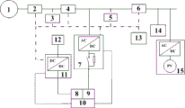
Fig. 1 is a schematic structural diagram of a microgrid energy storage and conversion regulation system of the present invention.
Description of reference numerals:
1. a power grid; 2. a first current sensor; 3. a first voltage sensor; 4. a switch; 5. a second voltage sensor; 6. a second current sensor; 7. a bidirectional full-bridge inverter; 8. a backup energy storage battery pack; 9. an energy storage battery pack; 10. a battery management system; 11. a DC/DC converter; 12. an electric vehicle charging pile; 13. a master controller; 14. a photovoltaic local load; 15. provided is a photovoltaic power generation device.
Detailed Description
It is to be understood that the following detailed description is exemplary and is intended to provide further explanation of the utility model as claimed. Unless defined otherwise, all technical and scientific terms used herein have the same meaning as commonly understood by one of ordinary skill in the art to which this invention belongs.
It is noted that the terminology used herein is for the purpose of describing particular embodiments only and is not intended to be limiting of exemplary embodiments according to the utility model.
The embodiments and features of the embodiments of the present invention may be combined with each other without conflict.
Example one
As shown in fig. 1, the present embodiment discloses a microgrid energy storage and conversion regulation system, which includes: the system comprises a photovoltaic power generation system, an energy storage converter, a detection unit, a selector switch and a master controller; the photovoltaic power generation system is connected with the energy storage converter in parallel through an alternating current bus; the detection unit is connected with the photovoltaic power generation system and used for detecting a voltage and current signal of the photovoltaic power generation system; the detection unit is in communication connection with the master controller; the master controller controls the energy storage converter to charge and discharge according to the voltage and current signals of the detection unit; the power grid is connected with the alternating current bus through the change-over switch; the photovoltaic power generation system comprises a photovoltaic power generation device, an alternating current/direct current converter is arranged in the photovoltaic power generation device, a direct current source end of the alternating current/direct current converter is connected with the photovoltaic panel, and an alternating current source end of the alternating current/direct current converter is connected with an alternating current bus; and a photovoltaic local load is connected between the alternating current power supply end of the alternating current/direct current converter and the alternating current bus.
The change-over switch 4 is connected with the power grid 1, the change-over switch 4 is connected with the energy storage converter and the photovoltaic power generation system through an alternating current bus copper bar, and the master controller 13 controls the change-over switch 4 through the communication manager to carry out grid-connected and off-grid switching on the microgrid.
In an embodiment, the power grid 1 may be a 35kV substation, and may also be a utility power grid.
Preferably, the switch 4 may be a relay switch.
The energy storage converter comprises a bidirectional full-bridge converter 7 and an energy storage battery pack 9, wherein the bidirectional full-bridge converter 7 is provided with two power input and output ends, namely an alternating current power end and a direct current power end, an alternating current bus of the system is connected to the alternating current power end of the bidirectional full-bridge converter 7, and the energy storage battery pack 9 is connected with the direct current power end of the bidirectional full-bridge converter 7; the master controller 13 sends out a driving signal to control the bidirectional full-bridge converter 7, so as to form a bidirectional power path for charging and discharging.
Specifically, the bidirectional full-bridge converter 7 can work in two modes of rectification and inversion through PWM control: in the inversion mode, the master controller 13 controls the energy storage battery pack 9 to discharge through the bidirectional full-bridge converter 7; in the rectification mode, the master controller 13 controls the energy storage battery pack 9 to charge through the bidirectional full-bridge converter 7.
The photovoltaic power generation system comprises a photovoltaic power generation device 15, an alternating current/direct current converter is arranged in the photovoltaic power generation device, the alternating current/direct current converter is provided with two power supply ends, namely a direct current power supply end and an alternating current power supply end, the direct current power supply end of the alternating current/direct current converter is connected with a photovoltaic panel, the alternating current power supply end of the alternating current/direct current converter is connected with an alternating current bus, and a photovoltaic local load 14 is connected between the alternating current power supply end of the alternating current/direct current converter and the alternating current bus.
The detection unit comprises a second voltage sensor 5, the second voltage sensor 5 is connected in parallel with an alternating current outlet end of the photovoltaic power generation device 15, and is used for measuring alternating current voltage output by a photovoltaic side and transmitting a sensed voltage value to the master controller 13.
The detection unit further comprises a second current sensor 6, wherein the second current sensor 6 is connected in series between the photovoltaic power generation device 15 and the outlet end of the photovoltaic local load 14, and is used for measuring the current flowing between the photovoltaic power generation system and the energy storage and power grid and transmitting the sensed current value to the master controller 13.
In one embodiment, the general controller 13 communicates with the switch 4 and the bidirectional full-bridge inverter 7 through a communication manager.
The communication manager communicates with the master controller 13 through the ethernet; the communication manager communicates with the bidirectional full-bridge converter 7 through RS485 or Ethernet; the communication manager communicates with the change-over switch 4 through the RS 485.
In one embodiment, the ac/dc converter built in the photovoltaic power generation device may preferably be a three-phase full-bridge inverter circuit structure.
In an embodiment, the power grid monitoring device further comprises a first current sensor 2 connected in series with the power grid 1, wherein the first current sensor 2 is in communication connection with the overall controller 13 and is used for measuring three-phase currents of the power grid and transmitting the sensed current values to the overall controller 13.
In an embodiment, the power grid voltage monitoring device can further comprise a first voltage sensor 3 connected with the power grid 1, wherein the first voltage sensor 3 is in communication connection with the master controller 13 and is used for measuring the three-phase voltage of the power grid, transmitting the sensed voltage value to the master controller 13 and performing real-time communication with the master controller 13.
In an embodiment, the energy storage converter further includes a standby energy storage battery pack 8 connected in parallel with the energy storage battery pack 9 through a first switch, one end of the standby energy storage battery pack 8 is connected with the dc power source end of the bidirectional full-bridge converter 7 through the first switch, the other end of the standby energy storage battery pack 8 is connected with one end of a dc/dc converter 11 through a second switch, and the other end of the dc/dc converter 11 is connected with an electric vehicle charging pile 12 to supply power to the electric vehicle charging pile.
Specifically, the dc/dc converter 11 has two dc ends, one dc end is connected to the spare energy storage battery pack 8 through the second switch, and the other dc end is connected to the electric vehicle charging pile 12.
In one embodiment, the energy storage battery pack 9 and the spare energy storage battery pack 8 are welded by a plurality of lithium iron phosphate batteries or lead-acid batteries through busbars.
In an embodiment, the dc/dc converter 11 and the master controller 13 are communicatively connected through a communication manager, and the communication manager communicates with the dc/dc converter 11 through RS485 or ethernet.
In an embodiment, the energy storage converter further includes a battery management system 10 connected to the energy storage battery pack 9 and/or the backup energy storage battery pack 8, and the battery management system 10 is configured to monitor the state of charge of the energy storage battery pack 9 and/or the backup energy storage battery pack 8 in real time.
In one embodiment, the battery management system 10 is communicatively connected to the bidirectional full-bridge inverter 7 and the dc/dc inverter 11, respectively.
The bidirectional full-bridge converter device 7 is communicated with the battery management system 10 through RS 485; the bidirectional full-bridge converter 7, the battery management system 10 and the master controller 13 form a communication and control link.
The direct current/direct current converter device 11 is communicated with the battery management system 10 through RS 485; the dc/dc converter 11 forms a communication and control link with the battery management system 10 and the master controller 13.
In an embodiment, the dc/dc converter 11 adopts a buck-boost circuit structure.
In one embodiment, a plurality of energy storage current transformation devices are connected in parallel by respectively connecting alternating current power supply ends of the plurality of energy storage current transformation devices to an alternating current bus.
The operation principle of the micro-grid energy storage and conversion regulation system is as follows:
the master controller receives the detection data of the second voltage sensor and the second current sensor and judges:
when the master controller detects that the generated energy of the photovoltaic power generation system is not enough to meet the load requirement of the photovoltaic local load, the master controller controls the bidirectional full-bridge converter to discharge the energy storage battery pack under the PWM control to supply power to the photovoltaic power generation system, and current flows into the photovoltaic local load through the bidirectional full-bridge converter;
when the master controller detects that the photovoltaic power generation system has residual electricity, the master controller controls the bidirectional full-bridge converter to charge the energy storage battery pack under the PWM control, and current flows into the bidirectional full-bridge converter from the photovoltaic power generation system, so that the residual electricity of the photovoltaic power generation system is reduced and fed into a 35kV transformer substation, and the reverse power supply to the 220kV transformer substation is reduced.
In addition, a power operation curve can be preset in the master controller, and the adjustment of the energy storage and current transformation of the microgrid can be realized through peak-valley electricity prices, which specifically comprises the following steps:
in the peak-valley electricity price period, the energy storage converter device operates in a power supply state, the master controller controls the bidirectional full-bridge converter device to realize the discharge of the energy storage battery pack, and the current flows from the energy storage battery pack to the photovoltaic local load;
in the valley electricity price period, the energy storage converter operates in an energy storage state, the master controller controls the bidirectional full-bridge converter to charge the energy storage battery pack, and current flows from the 35kV transformer substation to the energy storage battery pack.
In addition, the electric energy quality analysis can be carried out on the sampling data of the second voltage sensor and the second current sensor through the master controller to realize the adjustment of the energy storage and current transformation of the microgrid, which specifically comprises the following steps:
if the total harmonic distortion rate of the current on the photovoltaic local load side is greater than a national standard value, the energy storage converter works in an inversion mode, and the total control generates a PWM control signal through calculation to control the energy storage converter to inject reverse compensation current;
if the unbalance degree of the photovoltaic local load side is larger than the national standard value, the energy storage converter works in an inversion mode, and the master controller generates a PWM control signal through calculation to control the energy storage converter to inject compensation current.
By controlling the energy storage converter device to work in different operation modes, the non-working time of the energy storage converter device is reduced, so that the electric energy consumption capability of the microgrid is enhanced, and the surplus electricity generated by the photovoltaic power generation system is reduced and fed into a 35kV transformer substation.
According to the microgrid energy storage and conversion system, the residual electricity generated by the photovoltaic power generation system is subjected to energy storage of electric energy through the energy storage and conversion device, so that the residual electricity generated by photovoltaic power generation is reduced and fed into a 35kV transformer substation, and further, the reverse power supply to a 220kV transformer substation is reduced; meanwhile, the electric energy stored by the energy storage converter device can provide power supply support for a local load on the photovoltaic side under the condition of poor weather conditions, and self-storage and self-utilization of the electric energy of the photovoltaic platform area are realized.
Although the embodiments of the present invention have been described with reference to the accompanying drawings, it is not intended to limit the scope of the present invention, and it should be understood by those skilled in the art that various modifications and variations can be made without inventive efforts by those skilled in the art based on the technical solution of the present invention.
Claims (10)
1. A microgrid energy storage and conversion regulation system is characterized by comprising: the system comprises a photovoltaic power generation system, an energy storage converter, a detection unit, a selector switch and a master controller; the photovoltaic power generation system is connected with the energy storage converter in parallel through an alternating current bus; the detection unit is connected with the photovoltaic power generation system and used for detecting a voltage and current signal of the photovoltaic power generation system; the detection unit is in communication connection with the master controller; the master controller controls the energy storage converter to charge and discharge according to the voltage and current signals of the detection unit; the power grid is connected with the alternating current bus through the change-over switch; the photovoltaic power generation system comprises a photovoltaic power generation device, an alternating current/direct current converter is arranged in the photovoltaic power generation device, a direct current source end of the alternating current/direct current converter is connected with the photovoltaic panel, and an alternating current source end of the alternating current/direct current converter is connected with an alternating current bus; and a photovoltaic local load is connected between the alternating current power supply end of the alternating current/direct current converter and the alternating current bus.
2. The microgrid energy storage and conversion regulation system of claim 1, wherein the energy storage and conversion device comprises a bidirectional full-bridge conversion device and an energy storage battery pack; the alternating current power supply end of the bidirectional full-bridge converter is connected with the alternating current bus, and the direct current power supply end of the bidirectional full-bridge converter is connected with the energy storage battery pack.
3. The microgrid energy storage and conversion regulation system of claim 2, wherein the energy storage battery pack is connected with a battery management system, and the battery management system is in communication connection with the bidirectional full-bridge conversion device.
4. The microgrid energy storage and conversion regulation system of claim 2, wherein the energy storage and conversion device further comprises a standby energy storage battery pack, the standby energy storage battery pack is connected with a direct current power supply end of the bidirectional full-bridge conversion device through a first switch, the standby energy storage battery pack is connected with a direct current end of one end of the direct current/direct current conversion device through a second switch, and a direct current end of the other end of the direct current/direct current conversion device is connected with an electric vehicle charging pile.
5. The microgrid energy storage conversion regulation system of claim 1 further comprising a first current sensor connected in series with a power grid, the first current sensor communicatively connected to the master controller.
6. The microgrid energy storage conversion regulation system of claim 1 further comprising a first voltage sensor connected to the power grid, the first voltage sensor being in communication connection with the master controller.
7. The microgrid energy storage and conversion regulation system of claim 1, wherein the detection unit comprises a second current sensor connected in series between the photovoltaic power generation device and a photovoltaic local load outlet terminal, and the second current sensor is in communication connection with the master controller.
8. The microgrid energy storage and conversion regulation system of claim 1, wherein the detection unit further comprises a second voltage sensor connected in parallel with an alternating current outlet terminal of the photovoltaic power generation device, and the second voltage sensor is in communication connection with the master controller.
9. The microgrid energy storage and conversion regulation system of claim 1, wherein the alternating current/direct current conversion device built in the photovoltaic power generation device can be a three-phase full-bridge inverter circuit structure.
10. The microgrid energy storage and conversion regulation system of claim 4, wherein the DC/DC conversion device is in communication connection with a master controller.
Priority Applications (1)
| Application Number | Priority Date | Filing Date | Title |
|---|---|---|---|
| CN202123076437.8U CN215419616U (en) | 2021-12-09 | 2021-12-09 | Little electric wire netting energy storage conversion governing system |
Applications Claiming Priority (1)
| Application Number | Priority Date | Filing Date | Title |
|---|---|---|---|
| CN202123076437.8U CN215419616U (en) | 2021-12-09 | 2021-12-09 | Little electric wire netting energy storage conversion governing system |
Publications (1)
| Publication Number | Publication Date |
|---|---|
| CN215419616U true CN215419616U (en) | 2022-01-04 |
Family
ID=79666004
Family Applications (1)
| Application Number | Title | Priority Date | Filing Date |
|---|---|---|---|
| CN202123076437.8U Active CN215419616U (en) | 2021-12-09 | 2021-12-09 | Little electric wire netting energy storage conversion governing system |
Country Status (1)
| Country | Link |
|---|---|
| CN (1) | CN215419616U (en) |
Cited By (2)
| Publication number | Priority date | Publication date | Assignee | Title |
|---|---|---|---|---|
| CN119070482A (en) * | 2024-09-02 | 2024-12-03 | 深圳市索克新能源有限公司 | A photovoltaic inverter intelligent control system |
| CN120511810A (en) * | 2025-05-20 | 2025-08-19 | 天津清研双辰储能科技有限公司 | Self-balancing loss-reducing and efficiency-increasing system for power generation connection of photovoltaic module |
-
2021
- 2021-12-09 CN CN202123076437.8U patent/CN215419616U/en active Active
Cited By (2)
| Publication number | Priority date | Publication date | Assignee | Title |
|---|---|---|---|---|
| CN119070482A (en) * | 2024-09-02 | 2024-12-03 | 深圳市索克新能源有限公司 | A photovoltaic inverter intelligent control system |
| CN120511810A (en) * | 2025-05-20 | 2025-08-19 | 天津清研双辰储能科技有限公司 | Self-balancing loss-reducing and efficiency-increasing system for power generation connection of photovoltaic module |
Similar Documents
| Publication | Publication Date | Title |
|---|---|---|
| CN103532158B (en) | A kind of micro-grid new energy hybrid energy storage system | |
| CN102624018B (en) | Distributed hybrid power supply type smart grid system and control method | |
| CN104410105B (en) | Based on dc bus cancellated Intelligent wind power field control method | |
| CN110635559A (en) | Energy-saving and consumption-reducing back-up power system for wind power storage communication base station | |
| CN111446739A (en) | Power distribution station distribution system with distributed energy storage devices and control method thereof | |
| CN101931238A (en) | Coordinated control method of microgrid system based on master-slave strategy | |
| CN111628516A (en) | Low-voltage transformer area load adjusting system and method | |
| CN115714436A (en) | Stable power supply method of multi-energy storage power supply system suitable for traffic system | |
| CN209963766U (en) | A microgrid solar energy storage and charging energy control device with a common DC bus | |
| CN114156924A (en) | Micro-grid source-load-storage cooperative interaction control system and method | |
| CN112994059A (en) | Station network interactive type optical storage and charging intelligent charging station control architecture and control method | |
| CN211790793U (en) | Retired battery echelon utilization system | |
| CN105244909A (en) | Direct-current micro-grid system and grid-connection self-balancing control strategy | |
| CN112886626A (en) | Master-slave energy storage system of optical storage charging station and power tracking control method thereof | |
| CN203119615U (en) | Distributed direct-current independent power supply system | |
| CN114221374B (en) | Flexible substation area and its coordinated control method based on DC microgrid | |
| CN120879825A (en) | AC/DC series-parallel power distribution system | |
| CN213637085U (en) | Voltage sag compensation device | |
| CN212380952U (en) | Low-voltage transformer area load adjusting device | |
| CN209488257U (en) | Photovoltaic standby-based emergency power supply of direct current system of transformer substation | |
| CN207150185U (en) | A kind of intelligent substation micro-grid system | |
| CN215344073U (en) | Power supply system | |
| CN211930271U (en) | An intelligent energy storage device for distribution transformer capacity increase | |
| CN212323743U (en) | Organic Rankine cycle power generation, charging and discharging energy storage integrated system | |
| CN210273512U (en) | A microgrid control system |
Legal Events
| Date | Code | Title | Description |
|---|---|---|---|
| GR01 | Patent grant | ||
| GR01 | Patent grant |