Energy-saving environment-friendly LED lamp
Technical Field
The utility model relates to the technical field of LED lamps, in particular to an energy-saving and environment-friendly LED lamp.
Background
The LED, namely a semiconductor light-emitting diode, is a solid semiconductor device, can directly convert electricity into light, and the LED energy-saving lamp adopts a high-brightness white light-emitting diode light-emitting source, so that the LED energy-saving lamp has the advantages of high luminous efficiency, low power consumption, long service life, easy control, no maintenance, safety and environmental protection; the LED light source is a new generation solid cold light source, has soft and bright light color, rich and colorful property, low loss and low energy consumption, is green and environment-friendly, and is suitable for long-time illumination of families, markets, banks, hospitals, hotels and restaurants and other various public places. The LED lamp has the advantages that direct current is not needed, the eye is well protected, and the LED lamp is the best choice for a desk lamp and a flashlight, so that the LED lamp has the effects of energy conservation and environmental protection.
The LED lamp is mostly installed on the top of a wall, so tools such as a ladder are needed in the installation process, the installation mode of the lampshade and the lamp holder is mostly in a buckling or screw mode in the installation process of the current LED lamp, the inconvenience brought by the installation mode comprises the fact that the LED lamp and the lamp holder need to be aligned to each other in the installation process, and inconvenience is brought to the installation environment with a certain height.
SUMMERY OF THE UTILITY MODEL
The present invention aims to provide an energy-saving and environment-friendly LED lamp to solve the problems mentioned in the background section above.
In order to achieve the purpose, the utility model adopts the following technical scheme:
an energy-saving and environment-friendly LED lamp comprises a lamp holder, wherein an annular LED lamp body is fixedly mounted on the inner wall of the bottom of the lamp holder through first screws, an annular placing groove is formed in the annular inner side wall of the lamp holder, a plurality of first clamping grooves are formed in the annular side wall of the lamp holder and communicated with the annular placing groove, first magnets are fixedly clamped inside the first clamping grooves, a plurality of through holes are formed in the annular outer side wall of the lamp holder, the bottom walls of the through holes are flush with the bottom wall of the annular placing groove, limiting clamping blocks are inserted into the through holes, a second clamping groove is formed in one side of each limiting clamping block, a second magnet is fixedly clamped inside the second clamping groove, a lamp shade is arranged in the annular placing groove, a first annular mounting groove corresponding to the first magnet in position is formed in the lamp shade, a first annular iron sheet attracted with the first magnet is fixedly bonded inside the first annular mounting groove, a second annular mounting groove is formed in the lower portion of the first annular mounting groove, a second annular iron sheet is fixedly bonded in the second annular mounting groove, one end of the limiting clamping block is inserted into the second annular mounting groove, and the second magnet and the second annular iron sheet attract each other.
Furthermore, the number of the first clamping grooves is eight, and the eight first clamping grooves are uniformly distributed on the annular side wall of the lamp holder.
Furthermore, the number of the through holes is four, and the four through holes are uniformly distributed on the annular outer side wall of the lamp holder.
Furthermore, the outer surface of the limiting clamping block is fixedly connected with a pull ring.
Compared with the prior art, the utility model has the beneficial effects that:
when the LED lamp is installed, the bottom of the lamp shade is inserted into the annular placing groove in the lamp holder, the first magnet positioned in the first clamping groove is attracted with the first annular iron sheet in the first annular installing groove to realize the initial installation and fixation of the lamp shade, then the limiting clamping block is clamped into the lamp holder along the through hole through the pull ring and is inserted into the second annular installing groove in the lamp shade, and the second magnet and the second annular iron sheet are attracted at the moment to finish the installation and fixation of the LED lamp.
Drawings
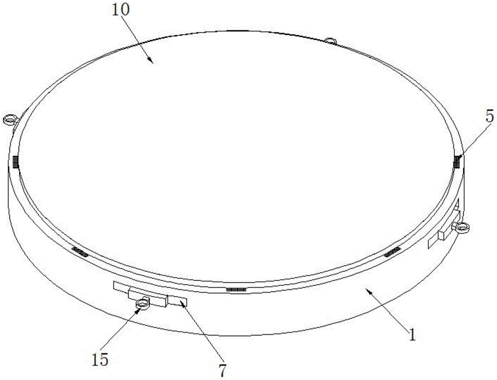
FIG. 1 is a schematic view of an overall structure of an embodiment of an energy-saving and environment-friendly LED lamp provided by the present invention;
FIG. 2 is a schematic diagram of a front view structure of an embodiment of an energy-saving and environment-friendly LED lamp provided by the present invention;
FIG. 3 is a schematic diagram of an overall internal structure of an embodiment of an energy-saving and environment-friendly LED lamp according to the present invention;
FIG. 4 is a schematic diagram of an internal top view structure of an energy-saving and environment-friendly LED lamp according to an embodiment of the present invention;
FIG. 5 is a schematic view of an internal overall structure of a lamp holder of an embodiment of an energy-saving and environment-friendly LED lamp provided by the utility model;
FIG. 6 is a schematic diagram of a top view structure inside a lamp socket of an embodiment of an energy-saving and environment-friendly LED lamp provided by the utility model;
FIG. 7 is a schematic diagram of an overall structure of a limiting fixture block and a pull ring of an embodiment of an energy-saving and environment-friendly LED lamp provided by the utility model;
FIG. 8 is a schematic diagram of a top view structure of a limiting fixture block and a pull ring of an embodiment of an energy-saving and environment-friendly LED lamp provided by the utility model;
FIG. 9 is a schematic view of an overall structure of a lampshade of an energy-saving and environment-friendly LED lamp according to an embodiment of the utility model;
FIG. 10 is a schematic diagram of a front view of a lampshade of an energy-saving and environment-friendly LED lamp according to an embodiment of the present invention;
FIG. 11 is a schematic view of a bottom view of a lampshade of an energy-saving and environment-friendly LED lamp according to an embodiment of the present invention;
fig. 12 is a schematic structural diagram of a portion a of an energy-saving and environment-friendly LED lamp according to an embodiment of the present invention.
In the figure: the LED lamp comprises a lamp holder 1, an annular LED lamp body 2, an annular placing groove 3, a first clamping groove 4, a first magnet 5, a through hole 6, a limiting clamping block 7, a second clamping groove 8, a second magnet 9, a lampshade 10, a first annular mounting groove 11, a first annular iron sheet 12, a second annular mounting groove 13, a second annular iron sheet 14, a pull ring 15 and a screw hole 16.
Detailed Description
The technical solutions in the embodiments of the present invention will be clearly and completely described below with reference to the drawings in the embodiments of the present invention, and it is obvious that the described embodiments are only a part of the embodiments of the present invention, and not all of the embodiments.
Referring to fig. 1-12, an energy-saving and environment-friendly LED lamp comprises a lamp holder 1, an annular LED lamp body 2 is tightly mounted on the inner wall of the bottom of the lamp holder 1 through a first screw, an annular accommodating groove 3 is formed on the inner wall of the annular of the lamp holder 1, eight first clamping grooves 4 are formed on the annular side wall of the lamp holder 1 and are uniformly distributed, the eight first clamping grooves 4 are communicated with the annular accommodating groove 3, first magnets 5 are fixedly clamped inside the eight first clamping grooves 4, four uniformly distributed through holes 6 are formed on the annular outer side wall of the lamp holder 1, the bottom walls of the through holes 6 are flush with the bottom wall of the annular accommodating groove 3, limiting clamping blocks 7 are inserted into the four through holes 6, a second clamping groove 8 is formed on one side of each limiting clamping block 7, a second magnet 9 is fixedly clamped inside the second clamping groove 8, a lampshade 10 is arranged in the annular accommodating groove 3, a first annular mounting groove 11 corresponding to the position of the first magnet 5 is formed on the lampshade 10, the inside fixed bonding of first annular mounting groove 11 has first annular iron sheet 12 of inhaling mutually with first magnet 5, and second annular mounting groove 13 has been seted up to the below of first annular mounting groove 11, and the inside fixed bonding of second annular mounting groove 13 has second annular iron sheet 14, and the one end of spacing fixture block 7 inserts to second annular mounting groove 13 in, and second magnet 9 and second annular iron sheet 14 inhale mutually.
In the above embodiment, when the energy-saving and environment-friendly LED lamp of the utility model is installed, first, second screws are inserted into four screw holes 16 in the lamp holder 1 to fix the lamp shade 10 to the wall, then, the bottom of the lamp shade 10 is inserted into the annular placing groove 3 in the lamp holder 1, the first magnet 5 in the first clamping groove 4 is attracted to the first annular iron sheet 12 in the first annular placing groove 11, so as to achieve the initial installation and fixation of the lamp shade 10, then, the pull ring 15 is used to clip the limiting clamping block 7 into the lamp holder 1 along the through hole 6 and to be inserted into the second annular placing groove 13 on the lamp shade 10, and at this time, the second magnet 9 is attracted to the second annular iron sheet 14, so as to complete the installation and fixation of the LED lamp, and the lamp shade 10 can be inserted into the annular placing groove 3 in the lamp holder 1 at any angle without alignment, so that the installation is convenient and fast.
Specifically, the outer surface of the limiting fixture block 7 is fixedly connected with a pull ring 15.
In the above embodiment, the movement of the limit latch 7 is facilitated by the pull ring 15.
The above description is only for the preferred embodiment of the present invention, but the scope of the present invention is not limited thereto, and any person skilled in the art should be considered to be within the technical scope of the present invention, and equivalent alternatives or modifications according to the technical solution of the present invention and the inventive concept thereof should be covered by the scope of the present invention.